MX204 AC Power System
MX204 Power System Description
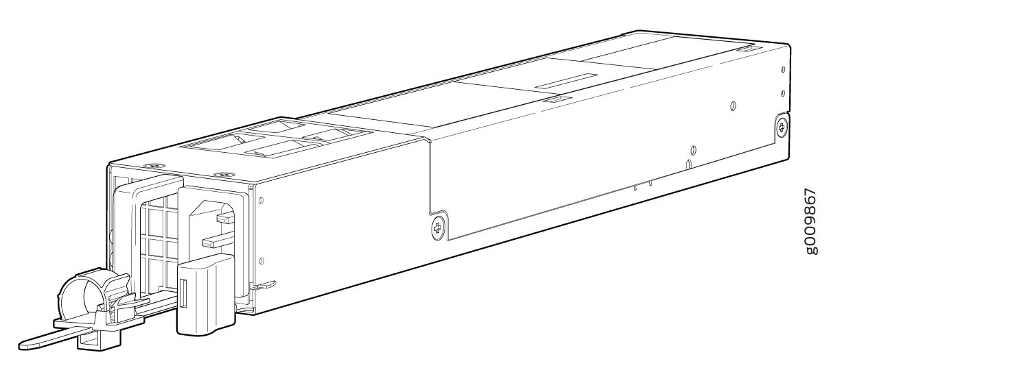
The MX204 is powered using either AC or DC power. It supports two power supply modules (PSMs) located at the rear of the chassis in slots 0 and 1. Figure 1 and Figure 2 show the MX204 PSMs. The AC or DC power supply modules directly plug on to main board and are placed on the right side of the rear chassis. Each power supply has a handle, an ejector lever, and status LEDs. The power supply modules connect to the PSM board, which distributes the different output voltages produced by the power supply modules to the router components, depending on their voltage requirements. When both the power supply modules are present, they share power almost equally within a fully populated system. If the first power supply in a redundant configuration fails or is removed, the second power supply assumes the entire electrical load without interruption. A single power supply provides the maximum configuration with full power for as long as the router is operational. A second power supply can be installed for redundancy. The chassis is designed to support 1+1 feed redundancy.
Redundant power supply is hot-removable and hot-insertable. If you remove a power supply from a router that uses only one power supply, then the router shuts down.
Do not mix AC and DC power supply modules in the same chassis.
Routers configured with only one power supply are shipped with a blank panel installed over the power supply slot that is not populated.
The power supply modules are cooled by its own internal cooling system. A fan present in the power supply module monitors and maintains the temperature inside.
AC Power Supply Description
Each AC power supply weighs approximately 2.2 lb (1 kg) and consists of a handle, an ejector lever, an AC appliance inlet, a fan, and status LEDs to monitor the status of the power supply. Figure 1 shows the AC power supply.
Each inlet requires a dedicated AC power feed and a dedicated customer-site circuit breaker. We recommend that you use a minimum 20 A (110 VAC) or 16 A (220 VAC) customer-site circuit breaker, or as required by local code.
The router is pluggable type A equipment installed in a restricted-access location. It has a separate protective earthing terminal (sized for 10–32 screws) provided on the chassis in addition to the grounding pin of the power supply cord. This separate protective earthing terminal must be permanently connected to earth.
DC Power Supply Description
Each DC power supply weighs approximately 2.2 lb (1 kg) and consists of a handle, an ejection lever, status LEDs, and a terminal block that provides a single DC input (–48 VDC and return) that requires a dedicated customer site circuit breaker. We recommend that you use a dedicated customer-site circuit breaker rated for 25 A (–48 VDC) minimum, or as required by local code.
Figure 2 shows the DC power supply.

See Also
MX204 Power Supply Module LEDs
AC Power Supply Module LEDs
Figure 3 shows the AC power supply module components along with the status LEDs.
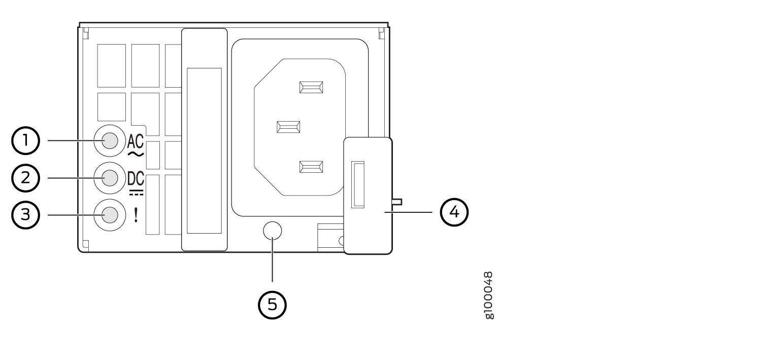
1 — Input status LED | 4 — Ejector lever |
2 — Output status LED | 5 — AC power cord retainer port |
3 — Fault LED |
Figure 4 shows the AC power supply module components with the AC power cord retainer along with the status LEDs.
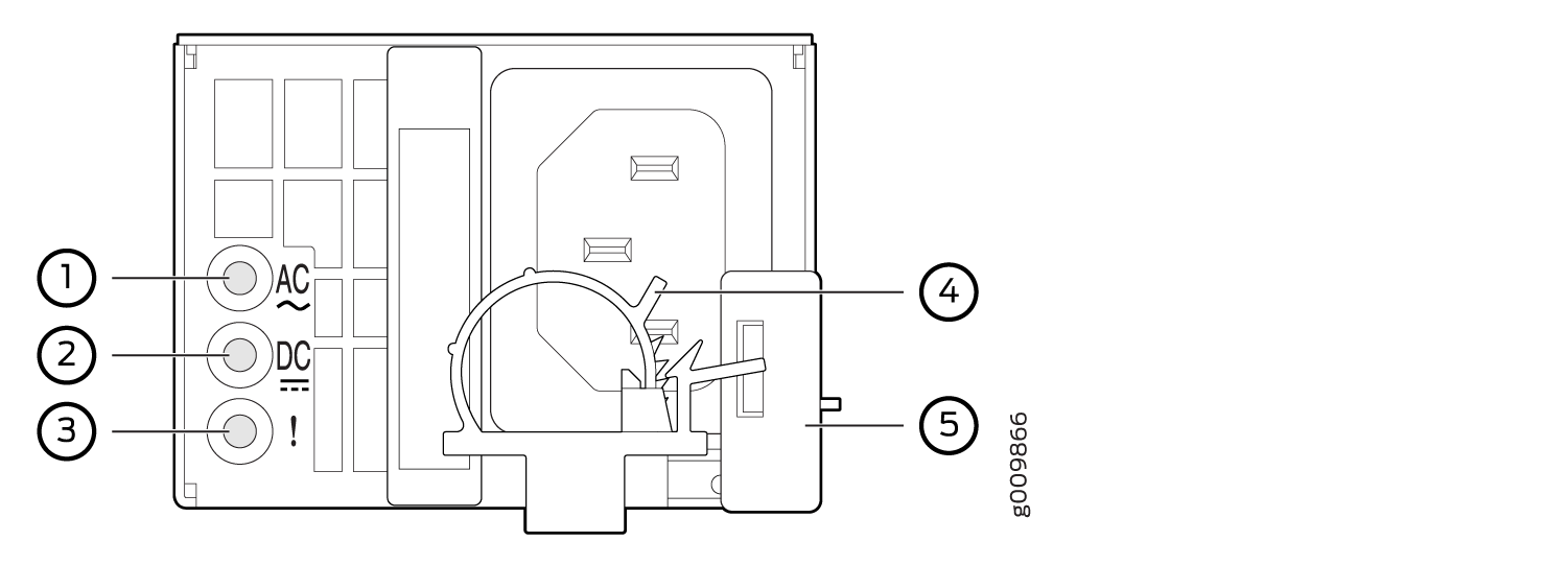
1 — Input status LED | 4 — AC power cord retainer installed |
2 — Output status LED | 5 — Ejector lever |
3 — Fault LED |
Table 1 describes the LEDs on the AC power supply modules.
|
Label |
Color |
State |
Description |
|---|---|---|---|
|
AC OK |
Unlit |
Off |
The power supply is disconnected from power source, or the power supply is not receiving power. |
|
Green |
On steadily |
Power supply is receiving power. |
|
|
DC OK |
Unlit |
Off |
Power supply output is off. |
|
Green |
On steadily |
The power supply is sending out power correctly. |
|
|
! (Fault) |
Amber |
On steadily |
An error has been detected in the power supply. Replace the power supply as soon as possible. To maintain proper airflow through the chassis, leave the power supply installed in the chassis until you are ready to replace it. |
If the AC OK LED and the DC OK LED are unlit, either the AC power cord is not installed properly or the power supply fuse has failed. If the AC OK LED is lit and the DC OK LED is unlit, the AC power supply is installed properly, but the power supply has an internal failure.
DC Power Supply Module LEDs
Figure 5 shows the DC power supply modules status LEDs.
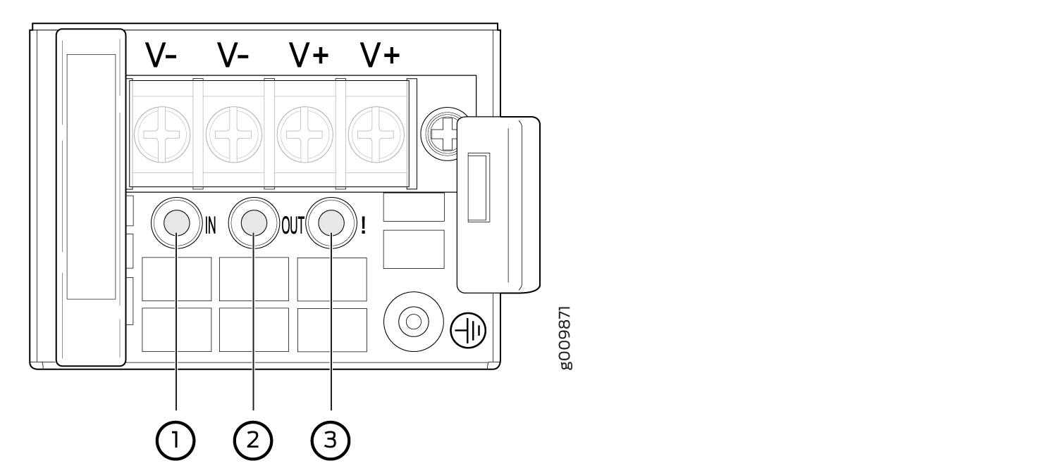
1 — Input LED | 3 — Fault LED |
2 — Output LED |
On the DC power supply, the V+ terminals are shunted internally together, as are the V– terminals. The same polarity terminal can be wired together from the same source to provide an additional current path in a higher power chassis. Do not connect the terminals to different sources.
Table 2 describes the LEDs on the DC power supply modules.
|
Label |
Color |
State |
Description |
|---|---|---|---|
|
IN (Input) |
Unlit |
Off |
The power supply is disconnected from power source, or the power supply is not receiving power. |
|
Green |
On steadily |
Power supply is receiving power. |
|
|
OUT (Output) |
Unlit |
Off |
Power supply output is off. |
|
Green |
On steadily |
The power supply is sending out power correctly. |
|
|
! (Fault) |
Amber |
On steadily |
An error has been detected in the power supply. Replace the power supply as soon as possible. To maintain proper airflow through the chassis, leave the power supply installed in the chassis until you are ready to replace it. |
See Also
MX204 Router AC Power Specifications
Table 3 lists the AC power system electrical specifications.
Item |
Specification |
|---|---|
AC input voltage |
Operating range: 100 through 240 VAC |
AC input line frequency |
50 through 60 Hz (nominal) |
AC system current rating |
3.2 A @ 100 VAC 1.37 A @ 240 VAC |
AC system input power |
312 W |
Table 4 lists the AC power supply electrical specifications.
Item |
Specification |
|---|---|
Maximum output power |
650 W |
AC input voltage |
Operating range: 100 through 127 VAC 200 through 240 VAC |
AC input line frequency |
50 to 60 Hz (nominal) |
AC input current rating |
7.8 A @ 100 VAC 3.8 A @ 240 VAC |
See Also
AC Power Circuit Breaker Requirements for the MX204 Router
We recommend that you use a dedicated customer-site circuit breaker rated for 20 A (110 VAC) minimum or 16 A (220 VAC) minimum for each AC power feed, or as required by local code. Doing so enables you to operate the router in any configuration without upgrading the power infrastructure.
See Also
AC Power Cord Specifications for MX204 Routers
You can order detachable AC power cords based on your geographical location. The cord coupler is type C13 as described by International Electrotechnical Commission (IEC) standard 60320. The plug end of the power cord fits into the power source outlet that is standard for your geographical location.
Ensure that you use an AC power supply only with a power cord that is intended for it.
In North America, AC power cords must not exceed 4.5 meters (approximately 14.75 feet) in length, to comply with National Electrical Code (NEC) Sections 400-8 (NFPA 75, 5-2.2) and 210-52 and Canadian Electrical Code (CEC) Section 4-010(3). The cords supplied with the switch are in compliance.
Table 5 gives the AC power cord specifications for the countries and regions listed in the table.
Country/Region |
Electrical Specifications |
Plug Standards |
Juniper Model Number |
|---|---|---|---|
Argentina |
250 VAC, 10 A, 50 Hz |
IRAM 2073 Type RA/3 |
CBL-EX-PWR-C13-AR |
Australia |
250 VAC, 10 A, 50 Hz |
AS/NZZS 3112 Type SAA/3 |
CBL-EX-PWR-C13-AU |
Brazil |
250 VAC, 10 A, 50 Hz |
NBR 14136 Type BR/3 |
CBL-EX-PWR-C13-BR |
China |
250 VAC, 10 A, 50 Hz |
GB 1002-1996 Type PRC/3 |
CBL-EX-PWR-C13-CH |
Europe (except Italy, Switzerland, and United Kingdom) |
250 VAC, 10 A, 50 Hz |
CEE (7) VII Type VIIG |
CBL-EX-PWR-C13-EU |
India |
250 VAC, 10 A, 50 Hz |
IS 1293 Type IND/3 |
CBL-EX-PWR-C13-IN |
Israel |
250 VAC, 10 A, 50 Hz |
SI 32/1971 Type IL/3G |
CBL-EX-PWR-C13-IL |
Italy |
250 VAC, 10 A, 50 Hz |
CEI 23-16 Type I/3G |
CBL-EX-PWR-C13-IT |
|
Japan |
125 VAC, 12 A, 50 Hz or 60 Hz |
JIS 8303 |
CBL-EX-PWR-C13-JP |
Korea |
250 VAC, 10 A, 50 Hz or 60 Hz |
CEE (7) VII Type VIIGK |
CBL-EX-PWR-C13-KR |
North America |
125 VAC, 13 A, 60 Hz |
NEMA 5-15 Type N5-15 |
CBL-EX-PWR-C13-US |
South Africa |
250 VAC, 10 A, 50 Hz |
SABS 164/1:1992 Type ZA/13 |
CBL-EX-PWR-C13-SA |
Switzerland |
250 VAC, 10 A, 50 Hz |
SEV 6534-2 Type 12G |
CBL-EX-PWR-C13-SZ |
Taiwan |
125 VAC, 11 A and 15 A, 50 Hz |
NEMA 5-15P Type N5-15P |
CBL-EX-PWR-C13-TW |
United Kingdom |
250 VAC, 10 A, 50 Hz |
BS 1363/A Type BS89/13 |
CBL-EX-PWR-C13-UK |
Figure 6 illustrates the plug on the power cord for some of the countries or regions listed in Table 5.