Maintaining MX204 Components
Routine Maintenance Procedures for MX204 Routers
Purpose
For optimum router performance, perform preventive maintenance procedures.
Action
Inspect the installation site for moisture, loose wires or cables, and excessive dust. Make sure that airflow is unobstructed around the router and into the air intake vents.
Check the status-reporting devices on the font panel—system alarms and LEDs.
See Also
Maintaining the MX204 Routing Engine
Purpose
For optimum router performance, verify the condition of the Routing Engine on a regular basis.
Action
On a regular basis:
Check the LEDs on the front panel to view information about the status of the Routing Engine.
To check the status of the Routing Engine on the router, issue the
show chassis routing-enginecommand. The output is similar to the following:user@host> show chassis routing-engine Routing Engine status: Temperature 53 degrees C / 127 degrees F CPU temperature 53 degrees C / 127 degrees F DRAM 16341 MB (16384 MB installed) Memory utilization 6 percent 5 sec CPU utilization: User 0 percent Background 0 percent Kernel 0 percent Interrupt 0 percent Idle 100 percent 1 min CPU utilization: User 0 percent Background 0 percent Kernel 0 percent Interrupt 0 percent Idle 100 percent 5 min CPU utilization: User 0 percent Background 0 percent Kernel 0 percent Interrupt 0 percent Idle 100 percent 15 min CPU utilization: User 0 percent Background 0 percent Kernel 0 percent Interrupt 0 percent Idle 100 percent Model RE-S-2X00x6 Start time 2017-11-29 19:04:56 PST Uptime 5 days, 4 hours, 58 minutes, 44 seconds Last reboot reason 0x2000:hypervisor reboot Load averages: 1 minute 5 minute 15 minute 0.10 0.14 0.15
See Also
Replace an SFP, SFP+, or QSFP+ Transceiver
The transceivers for Juniper Networks devices are hot-removable and hot-insertable field-replaceable units (FRUs). You can remove and replace them without powering off the device or disrupting the device functions.
Remove a Transceiver
Before you begin removing a transceiver from a device, ensure that you have taken the necessary precautions for the safe handling of lasers (see Laser and LED Safety Guidelines and Warnings).
Ensure that you have the following parts and tools available:
An antistatic bag or an antistatic mat
Rubber safety caps to cover the transceiver and fiber-optic cable connector
A dust cover to cover the port or a replacement transceiver
After you remove a transceiver or when you change the media-type configuration, wait for 6 seconds for the interface to display the operational commands.
To remove a transceiver:
- By using your fingers, pull open the ejector lever on
the transceiver to unlock the transceiver.CAUTION:
Ensure that you open the ejector handle completely until you hear it click. Doing this prevents damage to the transceiver.
Figure 1 shows how to remove an SFP transceiver. The procedure is the same for SFP+ and QSFP+ transceivers.
Figure 1: Small Form-Factor Pluggable (SFP) Transceiver
After removing a transceiver from the chassis, wait at least 30 seconds before reinserting it or inserting a transceiver into a different slot.
Install a Transceiver
Before you begin to install a transceiver in a device, ensure that you have taken the necessary precautions for safe handling of lasers (see Laser and LED Safety Guidelines and Warnings).
Ensure that you have a rubber safety cap available to cover the transceiver.
After you insert a transceiver or after you change the media-type configuration, wait for 6 seconds for the interface to display operational commands.
We recommend that you use only optical transceivers and optical connectors purchased from Juniper Networks with your Juniper Networks device.
The Juniper Networks Technical Assistance Center (JTAC) provides complete support for Juniper-supplied optical modules and cables. However, JTAC does not provide support for third-party optical modules and cables that are not qualified or supplied by Juniper Networks. If you face a problem running a Juniper device that uses third-party optical modules or cables, JTAC may help you diagnose host-related issues if the observed issue is not, in the opinion of JTAC, related to the use of the third-party optical modules or cables. Your JTAC engineer will likely request that you check the third-party optical module or cable and, if required, replace it with an equivalent Juniper-qualified component.
Use of third-party optical modules with high-power consumption (for example, coherent ZR or ZR+) can potentially cause thermal damage to or reduce the lifespan of the host equipment. Any damage to the host equipment due to the use of third-party optical modules or cables is the users’ responsibility. Juniper Networks will accept no liability for any damage caused due to such use.
To install a transceiver:
- Slide in the transceiver until it is fully seated. If
you are unable to fully insert the transceiver, ensure that the connector
is facing the right way.Figure 2: Install a Transceiver
 1—
1—Ejector lever
Replace a QSFP28 Transceiver
28-Gbps quad small form-factor pluggable (QSFP28) transceivers are hot-insertable and hot-removable. Removing a QSFP28 transceiver does not interrupt router functioning, but the removed QSFP28 transceiver no longer receives or transmits data.
Remove a QSFP28 Transceiver
Before you begin to remove a transceiver from a device, ensure that you have taken the necessary precautions for safe handling of lasers (see Laser and LED Safety Guidelines and Warnings).
Ensure that you have the following parts and tools available:
An antistatic bag or an antistatic mat
Rubber safety caps to cover the transceiver and fiber-optic cable connector
A dust cover to cover the port or a replacement transceiver
The transceivers for Juniper Networks devices are hot-removable and hot-insertable field-replaceable units (FRUs). You can remove and replace them without powering off the device or disrupting the device functions.
After you insert a transceiver or after you change the media-type configuration, wait for 6 seconds for the interface to display operational commands.
We recommend that you use only optical transceivers and optical connectors purchased from Juniper Networks with your Juniper Networks device.
To remove a QSFP28 transceiver (see Figure 3):
- Pull the transceiver’s rubber handle straight back.
The locking pins on the transceiver automatically releases the transceiver.
Figure 3: 28-Gbps Quad Small Form-Factor Pluggable (QSFP28) Transceiver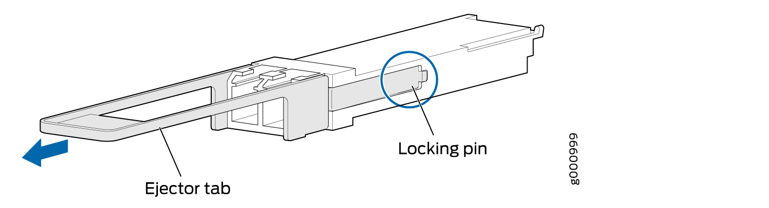
Install a QSFP28 Transceiver
Before you begin to install a transceiver in a device, ensure that you have taken the necessary precautions for safe handling of lasers (see Laser and LED Safety Guidelines and Warnings).
Ensure that you have a rubber safety cap available to cover the transceiver.
The transceivers for Juniper Networks devices are hot-removable and hot-insertable field-replaceable units (FRUs): You can remove and replace them without powering off the device or disrupting the device functions.
After you insert a transceiver or after you change the media-type configuration, wait for 6 seconds for the interface to display operational commands.
We recommend that you use only optical transceivers and optical connectors purchased from Juniper Networks with your Juniper Networks device.
The Juniper Networks Technical Assistance Center (JTAC) provides complete support for Juniper-supplied optical modules and cables. However, JTAC does not provide support for third-party optical modules and cables that are not qualified or supplied by Juniper Networks. If you face a problem running a Juniper device that uses third-party optical modules or cables, JTAC may help you diagnose host-related issues if the observed issue is not, in the opinion of JTAC, related to the use of the third-party optical modules or cables. Your JTAC engineer will likely request that you check the third-party optical module or cable and, if required, replace it with an equivalent Juniper-qualified component.
Use of third-party optical modules with high-power consumption (for example, coherent ZR or ZR+) can potentially cause thermal damage to or reduce the lifespan of the host equipment. Any damage to the host equipment due to the use of third-party optical modules or cables is the users’ responsibility. Juniper Networks will accept no liability for any damage caused due to such use.
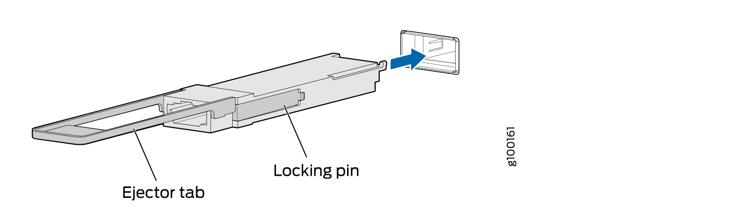
To install a replacement QSFP28 transceiver (see Figure 4):
- Orient the transceiver in front of the port so that the
QSFP28 connector faces the appropriate direction.Figure 4: Install a QSFP28 Transceiver