MX204 Host Subsystem
MX204 Routing Engine Description
The host subsystem provides routing protocol processes, as well as software processes that control the router’s interface, the chassis components, system management, and user access to the router. These routing processes run on top of a kernel that interacts with the Packet Forwarding Engine. The MX204 host subsystem consists of a single built-in Routing Engine.
This topic covers:
- Routing Engine Functions
- Routing Engine Components
- Routing Engine Front Panel
- Routing Engine Interface Ports
Routing Engine Functions
The Routing Engine is built-in on the MX204 baseboard and cannot be replaced. The Routing Engine performs all route-processing functions, and provides performs chassis control and management plane functionality. The Routing Engine also provides control plane functions.
The Routing Engine supports the following functionalities to manage the operation of the router:
System control functions such as environmental monitoring
Routing Layer 2 and Layer 3 protocols
Communication to components such as line cards, power supply, and cooling system
Transparent clocking
Alarm and logging functions
Routing Engine Components
The Routing Engine consists of the following internal components:
High-performance 1.6-GHz Intel 8 Core X86 CPU
32-GB DDR4 RAM
100-GB SATA SSD
Routing Engine Front Panel
Figure 1 shows the front panel of the MX204 chassis.
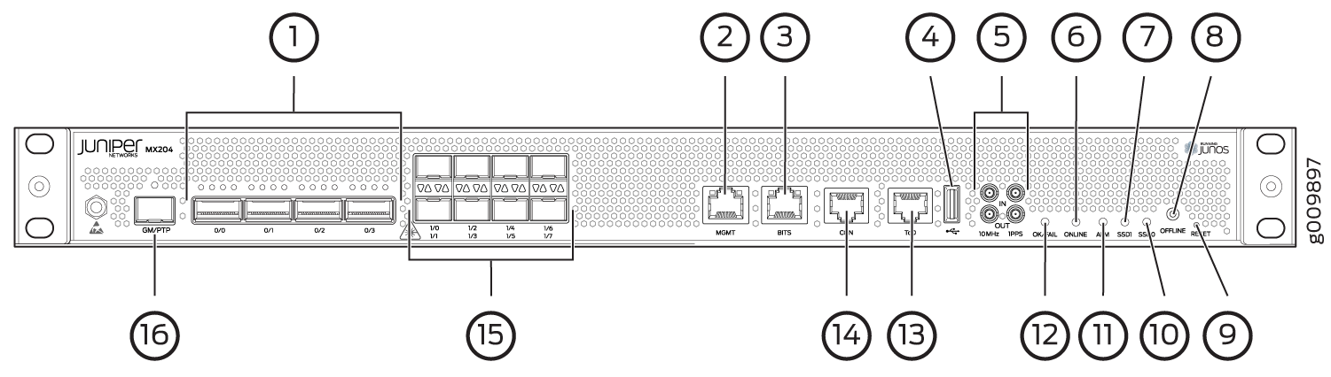
1 — Rate-selectable ports | 9 — RESET button |
2 — Management (MGMT) port | 10 — SSD0 LED |
3 — BITS port with LEDs | 11 — Alarm (ALM) LED |
4 — USB port | 12 — OK/FAIL LED |
5 — 1PPS and 10MHz GPS input and output ports | 13 — Time of day (ToD) port with LEDs (This port is reserved for future use) |
6 — ONLINE LED | 14 — Console (CON) port |
7 — SSD1 LED | 15 — 10-Gigabit Ethernet SFP+ ports |
8 — OFFLINE button | 16 — PTP grandmaster clock (GM/PTP) port |
Routing Engine Interface Ports
The ports located on the router connect the Routing Engine to one or more external devices on which system administrators can issue Junos OS CLI commands to manage the router. In addition, ports to connect external clock interfaces for BITS and GPS function are also available on the router.
The Routing Engine interface ports with the indicated labels function are as follows (see Figure 1):
CON—Connects the Routing Engine to a system console through a serial cable with an RJ-45 connector.
MGMT—Connects the Routing Engine through an Ethernet connection to a management LAN (or any other device that plugs into an Ethernet connection) for out-of-band management. The port uses an autosensing RJ-45 connector to support 10-Mbps, 100-Mbps, or 1000-Mbps connections. Two small LEDs (an activity LED and a link LED) on the port indicate the connection in use.
The link LED is:
lit amber (steady) when the 1000-Mbps link is up.
lit green (steady) when the 100-Mbps link is up.
Off when the 10-Mbps link is up.
The activity LED is:
lit green (blinking) when traffic is passing through the port.
lit green (steady) when traffic is not passing through the port.
Both activity and link LEDs are off when the link is down.
BITS—Building-integrated timing supply (BITS) external clocking interface for connecting to external clocking devices.
ToD—Time-of-day (TOD) port on the front panel of the router that enables you to connect external timing signal sources.
Note:This port is reserved for future use.
10MHZ (one input and one output)—The 10-MHz timing connectors on the front panel of the router that connect to external clock signal sources. The clocking ports provide the synchronized output clocks from any one of the reference clock inputs based on the clock’s priority.
PPS (one input and one output)—1-pulse-per-second (PPS) connectors on the front panel of the router that connect to external clock signal sources. The clocking ports provide the synchronized output clocks from any one of the reference clock inputs based on the clock’s priority.
USB—Provides a removable media interface through which you can install Junos OS manually. Junos OS supports USB version 1.0 and later.
See Also
MX204 Routing Engine LEDs
The Routing Engine is built-in on the MX204 and is attached to the baseboard and cannot be replaced. The status of the Routing Engine is displayed by the ONLINE and OK/FAIL LEDs on the front panel of the MX204 chassis.
Table 1 describes the functions and LEDs on the MX204 router.
The functioning of the MX204 router is controlled by the Routing Engine, and the LEDs present on the front panel of the router displays the status and functioning of the MX204 router.
|
Label |
Color |
State |
Description |
|---|---|---|---|
|
ONLINE |
Green |
On steadily |
Both Junos OS and Linux are successfully loaded on the router. |
|
Blinking |
Router is starting Junos OS. |
||
|
Red |
On steadily |
Router has loaded Linux. |
|
|
Blinking |
Router is starting Linux. |
||
|
– |
Off |
Router is offline. |
|
|
OK/FAIL |
Green |
On steadily |
Router is functioning normally. |
|
Red |
Blinking |
Router has failed. |
|
|
– |
Off |
Router is not powered on. |
|
|
ALM |
Red |
On steadily |
Major alarm—Indicates a critical condition that can cause the router to stop functioning. Possible causes include component failure, or any major software failure. |
|
Yellow |
On steadily |
Minor alarm—Indicates a serious but nonfatal error condition, such as a maintenance alert or a significant increase in component temperature. |
|
|
Red |
Blinking |
Both major and minor alarms—Indicates that both major and minor alarm conditions are present. |
|
|
– |
Off |
No alarms are present. |
|
|
SSD0 |
Green |
Blinking |
SSD0 is being accessed by the router. |
|
– |
Off |
SSD0 is not active or not being accessed. |
|
|
SSD1 |
Green |
Blinking |
SSD1 is being accessed by the router. |
|
– |
Off |
SSD1 is not active or not being accessed. |
|
|
BITS |
Green |
On Steadily (Activity LED; left) |
When there is no loss (BITS is in locked state). |
|
– |
Off (Activity LED; left) |
When there is loss of signal or loss of line. |
|
|
Amber |
On steadily (Link LED; right) |
When there is loss of signal or loss of line. |
|
|
– |
Off (Link LED; right) |
When there is no loss (BITS is in locked state). |