Maintaining MX204 Power System Components
Maintaining the MX204 Power Supplies
Purpose
For optimum router performance, verify the condition of the power supply modules.
Action
On a regular basis, check the power supply status:
To check the power supply status, issue the
show
chassis environment
CLI command. The output is similar to the following:user@host> show chassis environment Class Item Status Measurement Temp CB 0 Top Right Inlet Sensor OK 26 degrees C / 78 degrees F CB 0 Top Left Inlet Sensor OK 22 degrees C / 71 degrees F CB 0 Top Right Exhaust Sensor OK 31 degrees C / 87 degrees F CB 0 Top Left Exhaust Sensor OK 44 degrees C / 111 degrees F CB 0 CPU Core-0 Temp OK 35 degrees C / 95 degrees F CB 0 CPU Core-1 Temp OK 34 degrees C / 93 degrees F CB 0 CPU Core-2 Temp OK 34 degrees C / 93 degrees F CB 0 CPU Core-3 Temp OK 34 degrees C / 93 degrees F CB 0 CPU Core-4 Temp OK 33 degrees C / 91 degrees F CB 0 CPU Core-5 Temp OK 33 degrees C / 91 degrees F CB 0 CPU Core-6 Temp OK 33 degrees C / 91 degrees F CB 0 CPU Core-7 Temp OK 33 degrees C / 91 degrees F FPC 0 EA0_HMC0 Logic die OK 55 degrees C / 131 degrees F FPC 0 EA0_HMC0 DRAM botm OK 52 degrees C / 125 degrees F FPC 0 EA0_HMC1 Logic die OK 55 degrees C / 131 degrees F FPC 0 EA0_HMC1 DRAM botm OK 52 degrees C / 125 degrees F FPC 0 EA0 Chip OK 64 degrees C / 147 degrees F FPC 0 EA0-XR0 Chip OK 56 degrees C / 132 degrees F FPC 0 EA0-XR1 Chip OK 57 degrees C / 134 degrees F Power PEM 0 OK PEM 1 Ok Fans Fan Tray 0 Fan 0 OK Spinning at normal speed Fan Tray 0 Fan 1 OK Spinning at normal speed Fan Tray 1 Fan 0 OK Spinning at normal speed Fan Tray 1 Fan 1 OK Spinning at normal speed Fan Tray 2 Fan 0 OK Spinning at normal speed Fan Tray 2 Fan 1 OK Spinning at normal speedMake sure that the power and grounding cables are arranged so that they do not obstruct access to other router components.
Routinely check the status LEDs on the power supply faceplates and the craft interface to determine if the power supplies are functioning normally.
Check the red and yellow alarm LEDs on the craft interface. Power supply failure or removal triggers an alarm that causes one or both of the LEDs to light. You can display the associated error messages by issuing the following command:
user@host> show chassis alarms
Periodically inspect the site to ensure that the grounding and power cables connected to the router are securely in place and that there is no moisture accumulating near the router.
Do not mix AC and DC power supplies in the same chassis.
See Also
Replacing an MX204 AC Power Supply
Removing an MX204 AC Power Supply
Before you remove a power supply, be aware of the following:
The minimum required number of power supply modules must be present in the router at all times.
To maintain proper cooling and prevent thermal shutdown of the operating power supply unit, each power supply slot must contain either a power supply or a blank panel. If you remove a power supply, you must install a replacement power supply or a blank panel shortly after the removal.
After powering off a power supply, wait at least 60 seconds before turning it back on.
Do not mix AC and DC power supply modules in the same chassis.
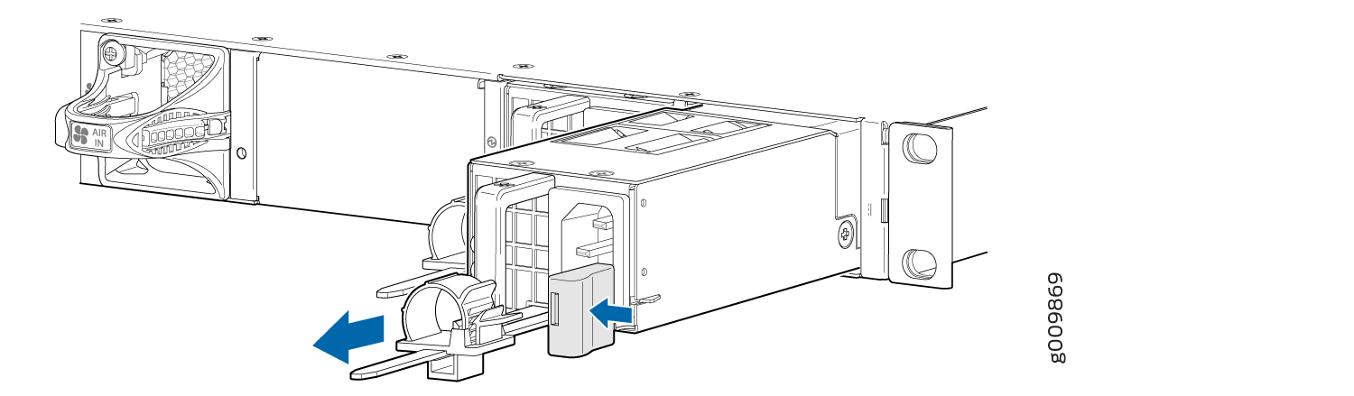
To remove an AC power supply (see Figure 1):
- Switch off the dedicated customer-site circuit breaker for the power supply, and remove the power cord from the AC power source. Follow the instructions for your site.
- Attach an ESD grounding strap to your bare wrist and connect the strap to one of the ESD points on the chassis.
- Remove the power cord from the power supply.
- Press the release latch on the side of the AC power supply to disconnect the power supply from the chassis (see Figure 1).
- Pull the power supply straight out of the chassis.
Installing an MX204 AC Power Supply
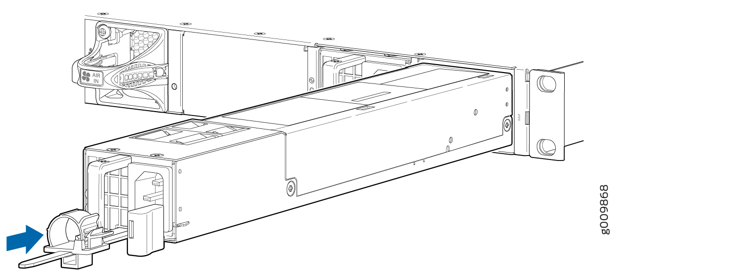
To install an AC power supply (see Figure 2):
- Attach an ESD grounding strap to your bare wrist and connect the strap to one of the ESD points on the chassis.
- Using both hands, hold and slide the AC power supply straight into the chassis until the power supply is fully seated in the chassis slot. The power supply faceplate must align with any adjacent power supply faceplate or blank installed in the power supply slot.
- Press the latch located on the side of the power supply to slide it into the chassis.
- Attach the power cord to the power supply.
- Attach the power cord to the AC power source, and switch on the dedicated customer-site circuit breaker. Follow the instructions for your site.
- Observe the status LED on the power supply faceplate. If the power supply is correctly installed and functioning normally, the status LED lights green steadily.
Replacing an MX204 DC Power Supply
Removing an MX204 DC Power Supply
Before you remove a power supply, be aware of the following:
The minimum required number of power supply modules must be present in the router at all times.
Before you perform DC power procedures, ensure there is no power to the DC circuit. To ensure that all power is off, locate the circuit breaker on the panel board that services the DC circuit, switch the circuit breaker to the off position, and tape the switch handle of the circuit breaker in the off position.
To maintain proper cooling and prevent thermal shutdown of the operating power supply unit, each power supply slot must contain either a power supply or a blank panel. If you remove a power supply, you must install a replacement power supply or a blank panel shortly after the removal.
After powering off a power supply, wait at least 60 seconds before turning it back on.
Do not mix AC and DC power supply modules in the same chassis.
To remove a DC power supply:
- Switch off the dedicated customer-site circuit breaker for the power supply being removed. Follow your site's procedures for ESD.
- Make sure that the voltage across the DC power source cable leads is 0 V and that there is no chance that the cables might become active during the removal process.
- Verify that the status LED on the power supply is not lit.
- Attach an ESD grounding strap to your bare wrist and connect the strap to one of the ESD points on the chassis.
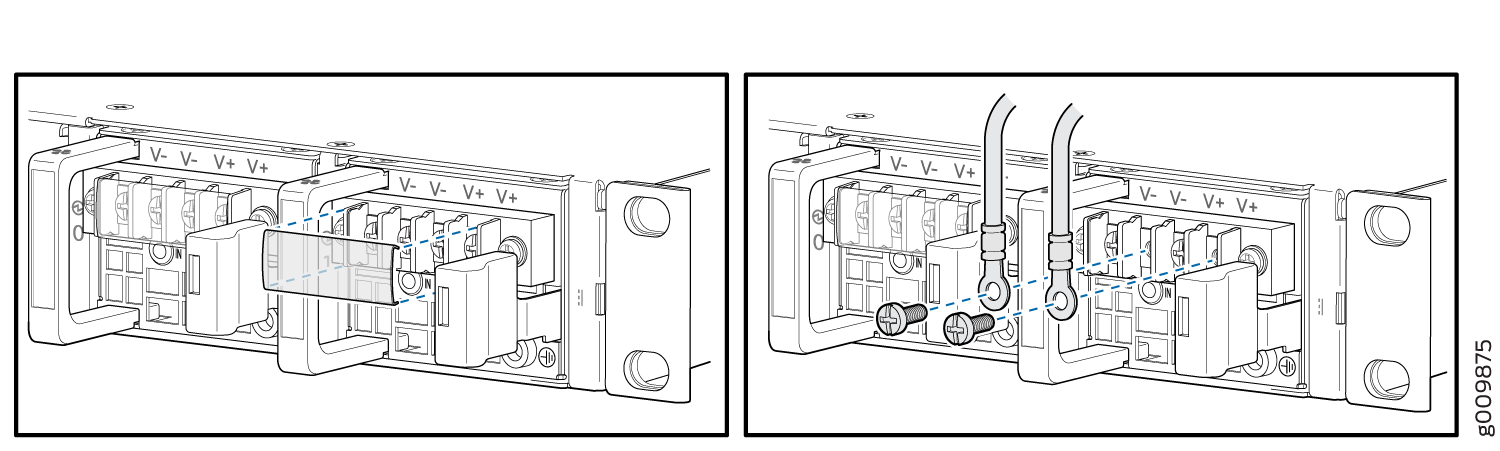
- Remove the clear plastic cover protecting the terminal studs on the faceplate.
- Using a socket screw driver, remove the screw from each of the DC power terminals (see Figure 3).
- Remove the cable lugs from the terminals.
- Carefully move the power cables out of the way.
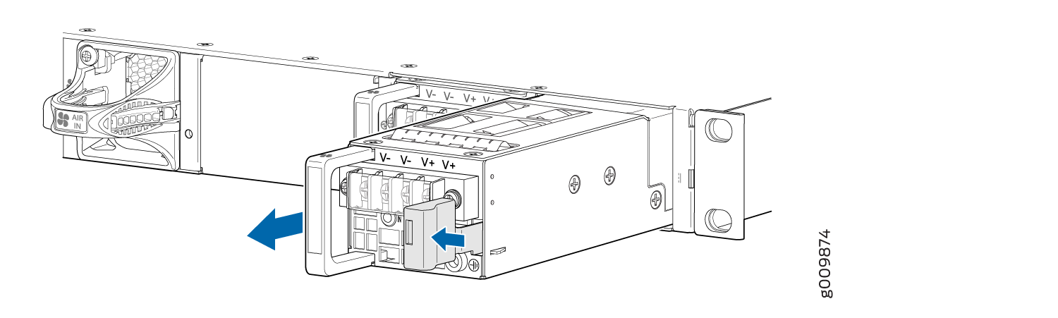
- Press the latch located on the DC power supply, to release it from the chassis.
- Pull the power supply straight out of the chassis (see Figure 4).
Installing an MX204 DC Power Supply
Before you perform DC power procedures, ensure there is no power to the DC circuit. To ensure that all power is off, locate the circuit breaker on the panel board that services the DC circuit, switch the circuit breaker to the off position, and tape the switch handle of the circuit breaker in the off position.
To install a DC power supply (see Figure 5):
