MX204 Site Guidelines and Requirements
MX204 Router Physical Specifications
Table 1 summarizes the physical specifications for the router.
Description |
Weight |
Width |
Depth |
Height |
|---|---|---|---|---|
Chassis fully loaded with all FRUs |
AC-powered chassis: 22.7 lb (10.3 kg) |
19 in. (48.26 cm) |
18.50 in. (47.0 cm) 20.43 in. (51.89 cm) with fan and power handles |
1.72 in. (4.37 cm; 1 U) |
Fan tray |
1.5 lb (0.68 kg) |
1.89 in. (4.8 cm) |
5.78 in. (14.68 cm) |
1.64 in. (4.17 cm) |
AC power supply |
2.2 lb (1 kg) |
2.23 in. (5.66 cm) |
14.50 in. (36.83 cm) |
1.58 in. (4.01 cm) |
DC power supply |
2.2 lb (1 kg) |
2.23 in. (5.66 cm) |
14.53 in. (36.91 cm) |
1.67 in. (4.24 cm) |
See Also
MX204 Router Environmental Specifications
Table 2 specifies the environmental specifications required for normal router operation. In addition, the site should be as dust-free as possible.
Description |
Value |
|---|---|
Altitude |
No performance degradation up to 10,000 ft (3048 m) |
Relative humidity |
Normal operation ensured in relative humidity range of 5% through 90%, noncondensing |
Temperature |
|
Seismic |
Designed to meet Telcordia Technologies Zone 4 earthquake requirements |
Maximum thermal output |
1705 BTU/hour (500 W) |
Install the router only in restricted-access areas, such as dedicated equipment rooms and equipment closets, in accordance with Articles 110-16, 110-17, and 110-18 of the National Electrical Code, ANSI/NFPA 70.
See Also
MX204 Router Grounding Specifications
Grounding Points Specifications
To meet safety and electromagnetic interference (EMI) requirements and to ensure proper operation, the router must be adequately grounded before power is connected. To ground AC-powered and DC-powered routers, you must connect a grounding cable to earth ground and then attach it to the chassis grounding points by using the two screws provided.
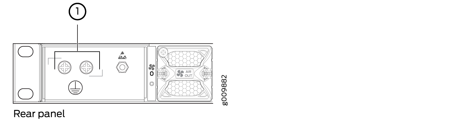
Figure 1 shows the grounding point location on the router.
A protective earthing terminal bracket is required for connecting the chassis to earth ground. This two-holed bracket attaches on the side of the chassis through the mounting rail and provides a protective earthing terminal for the router. The grounding points are studs sized for 10–32 screws. The 10–32 screws are provided with the MX204 router. The grounding points are spaced at 0.75-in. (19.1-mm) centers.
Two threaded holes are provided on the rear left side of the chassis for connecting the router to earth ground. The grounding points fit 10–32 screws.
Additional grounding is provided to an AC-powered router when you plug its power supply modules into grounded AC power receptacles.
You must install the MX204 router in a restricted-access location and ensure that the chassis is always properly grounded. The MX204 router has a two-hole protective grounding terminal provided on the chassis. See Figure 1. We recommend that you use this protective grounding terminal as the preferred method for grounding the chassis regardless of the power supply configuration. However, if additional grounding methods are available, you can also use those methods. For example, you can use the grounding wire in the AC power cord or use the grounding terminal or lug on a DC power supply. This tested system meets or exceeds all applicable EMC regulatory requirements with the two-hole protective grounding terminal.
Grounding Cable Lug Specifications
You must provide one grounding cable lug that attaches to the grounding cable and 10–32 screws used to secure the grounding cable to the grounding points.
Before you install the router, a licensed electrician must attach a cable lug to the grounding and power cables that you supply. A cable with an incorrectly attached lug can damage the router.
Grounding Cable Specifications
The grounding lug required is a Panduit LCD10-10A-L or equivalent (not provided). The grounding lug accommodates 12 AWG (2.5 mm²) stranded wire. The grounding cable that you provide for the chassis must be the same size or heavier than the input wire of each power supply module. Minimum recommendations are 12 AWG (2.5 mm²) stranded wire, 60° C wire, or as permitted by local code.
See Also
MX204 Router Rack Requirements
The MX204 router can be installed in a standard 19-in. rack. Many types of racks are acceptable, including four-post (telco) racks and open-frame racks. Table 3 summarizes rack requirements and specifications for the router.
Rack Requirement |
Guidelines |
|---|---|
Rack type and mounting bracket hole spacing |
Use a four-post rack. You can mount the router on any four-post rack that provides bracket holes or hole patterns spaced at 1 U (1.75-in./4.44-cm) increments and that meets the size and strength requirements specified in this table. A U is the standard rack unit defined in Cabinets, Racks, Panels, and Associated Equipment (document number EIA-310–D) published by the Electronics Components Industry Association (http://www.ecianow.org/). |
Rack size and strength |
|
Rack connection to the building structure |
|
See Also
MX204 Router Cabinet Requirements and Specifications
Table 4 summarizes cabinet requirements and specifications for the MX204 router.
Cabinet Requirement |
Guidelines for the MX204 Router |
|---|---|
Cabinet size and clearance |
|
Cabinet airflow requirements |
When you install the router in a cabinet, you must ensure that ventilation through the cabinet is sufficient to prevent overheating. Consider the following requirements to when planning for chassis cooling:
|
See Also
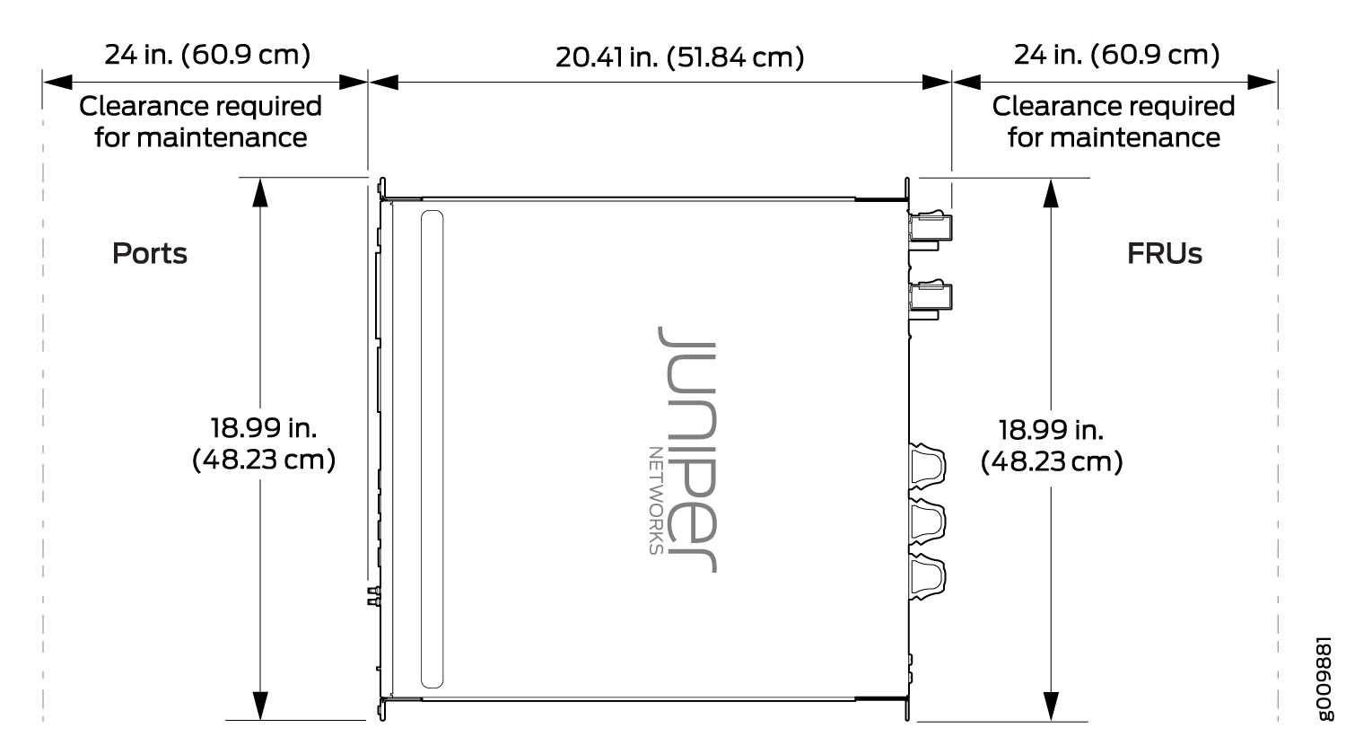
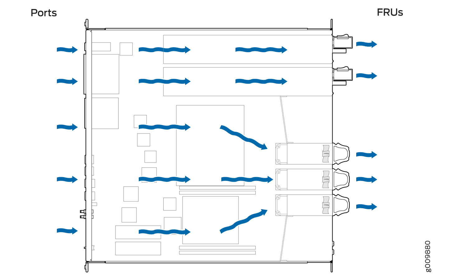
MX204 Router Clearance Requirements for Airflow and Hardware Maintenance
When planning the installation site, allow sufficient clearance around the rack (see Figure 3):
-
For the cooling system to function properly, the airflow around the chassis must be unrestricted. Allow at least 6 in. (15.2 cm) of clearance between side-cooled routers. Allow 2.8 in. (7 cm) between the side of the chassis and any non-heat-producing surface such as a wall.
-
For service personnel to remove and install hardware components, there must be adequate space at the front and back of the router. At least 24 in. (61 cm) are required both in front of and behind the router. NEBS GR-63 recommends that you allow at least 30 in. (76.2 cm) in front of the rack and 24 in. (61 cm) behind the router.
-
To accommodate power cable bend radius at the rear of the chassis and the interface cable bend radius at the front of the chassis, provide at least 2.75 in. (7 cm) at the rear and 3.5 in. (8.9 cm) at the front.