Help us improve your experience.

Let us know what you think.

Do you have time for a two-minute survey?


Connecting the MX204 to Power

Tools and Parts Required for MX204 Router Grounding and Power Connections

To ground and provide power to the router, you need the following tools and parts:

  • Phillips (+) screwdrivers, numbers 1 and 2

  • Socket nut driver

  • 2.5-mm flat-blade (–) screwdriver

  • Torque-controlled driver, with a maximum torque capacity of 6 lb-in. (0.7 Nm), for tightening screws to terminals on each power supply on a DC-powered router

    CAUTION:

    The maximum torque rating of the terminal screws on the DC power supply is 6 lb-in. (0.7 Nm). The terminal screws might be damaged if excessive torque is applied. Use only a torque-controlled driver to tighten screws on the DC power supply terminals. Use an appropriately sized driver, with a maximum torque capacity of 6 lb-in. or less. Ensure that the driver is undamaged and properly calibrated and that you have been trained in its use. You might want to use a driver that is designed to prevent overtorque when the preset torque level is achieved.

  • Wire cutters

  • Electrostatic discharge (ESD) grounding wrist strap

Grounding the MX204 Router

You must install the MX204 in a restricted-access location and ensure that the chassis is always properly grounded. The MX204 has a two-hole protective grounding terminal provided on the chassis. See Figure 2. Under all circumstances, use this grounding connection to ground the chassis. For AC-powered systems, you must also use the grounding wire in the AC power cord along with the two-hole grounding lug connection.. This tested system meets or exceeds all applicable EMC regulatory requirements with the two-hole protective grounding terminal.

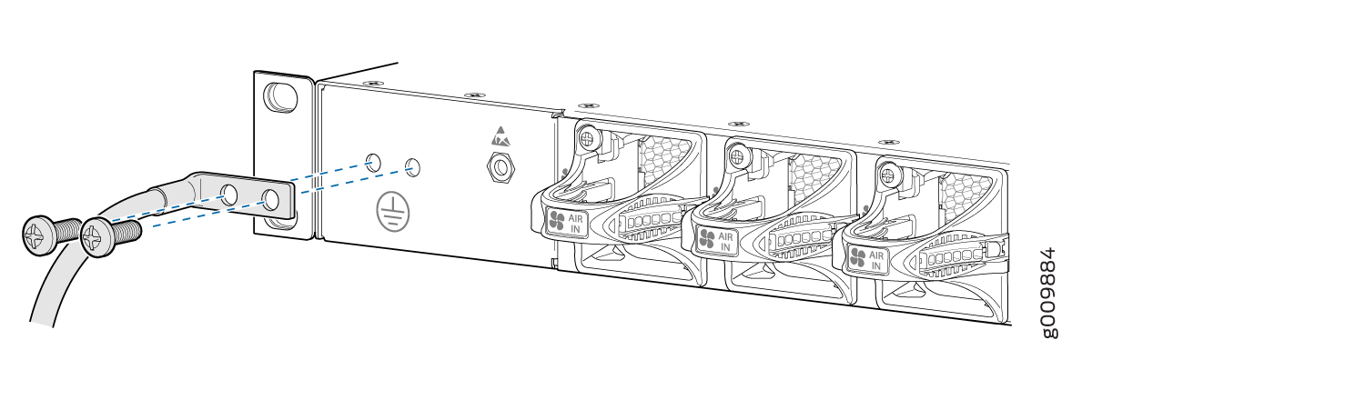
You ground the router by connecting a grounding cable to earth ground and then attaching it to the chassis grounding points by using two 10–32 screws. Figure 1 shows the grounding point location on the chassis. You must provide the grounding cables (the cable lugs are supplied with the router). For grounding cable specifications, see MX204 Router Grounding Specifications.
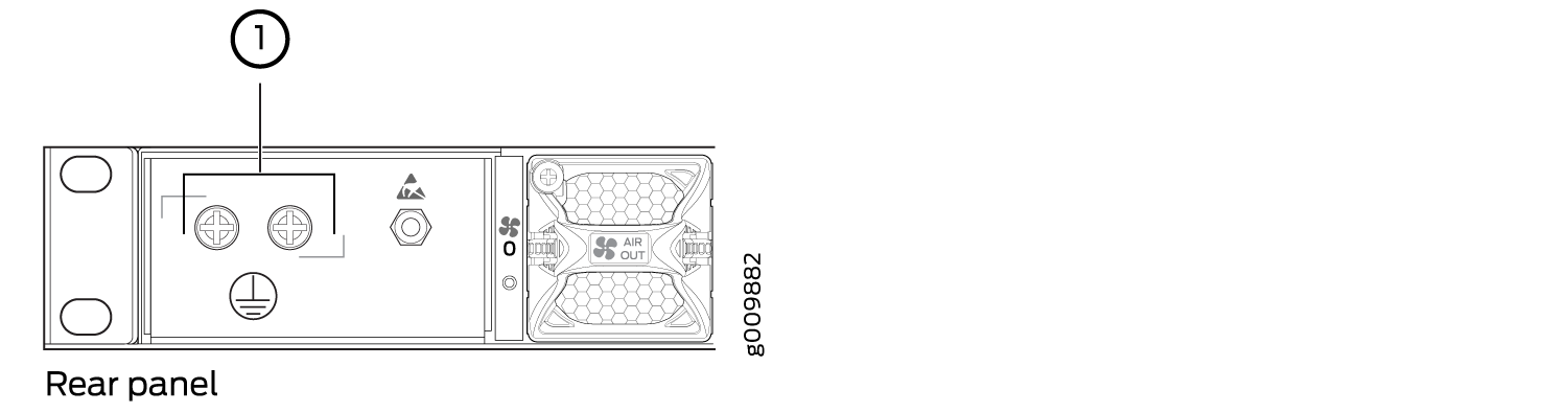
Figure 1: Grounding Point on the MX204 Router Grounding Point on the MX204 Router
  1

Grounding point


To ground the router:

  1. Verify that a licensed electrician has attached the cable lug provided with the router to the grounding cable.
  2. Attach an electrostatic discharge (ESD) grounding strap to your bare wrist, and connect the strap to an approved site ESD grounding point. See the instructions for your site.
  3. Ensure that all grounding surfaces are clean and brought to a bright finish before grounding connections are made.
  4. Connect the grounding cable to a proper earth ground.
  5. Detach the ESD grounding strap from the site ESD grounding point.
  6. Attach an ESD grounding strap to your bare wrist and connect the strap to one of the ESD points on the chassis.
  7. Place the grounding cable lug over the grounding point on the chassis.
  8. Secure the grounding cable lug with the screws. The holes are sized for 10–32 screws (see Figure 2).
  9. Dress the grounding cable, and verify that it does not touch or block access to router components, and that it does not drape where people could trip on it.
Figure 2: Connecting Grounding Lug to the MX204 RouterConnecting Grounding Lug to the MX204 Router

Connecting Power to an AC-Powered MX204 Router

CAUTION:

Do not mix AC and DC power supply modules within the same device. Mixing currents can damage the device.

You connect AC power to the router by attaching power cords from the AC power sources to the AC appliance inlets located on the power supply modules.

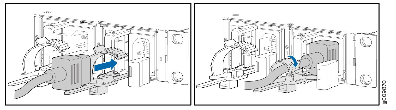
To connect the AC power cords to the router for each power supply module:

  1. Locate power cords that have a plug appropriate for your geographic location. For more information, see AC Power Cord Specifications for MX204 Routers.
  2. Attach an ESD grounding strap to your bare wrist and connect the strap to one of the ESD points on the chassis.
  3. Power off the AC input appliance inlet on the source power supply.
  4. Connect the power cord to the power supply source.
    Note:

    Each power supply must be connected to a dedicated AC power feed and a dedicated customer-site circuit breaker. We recommend that you use a dedicated customer-site circuit breaker rated for 20 A (110 VAC) or 16 A (220 VAC) minimum, or as required by local code.

  5. Push the end of the AC power cord retainer strip into the hole next to the inlet on the power supply face plate on the router until it snaps into place. Ensure that the loop in the retainer strip faces toward the power cord.

    Figure 3 shows the port on the AC power supply module where the power cord retainer is installed.

    Figure 3: Power Cord Retainer Port on the AC Power Supply Module
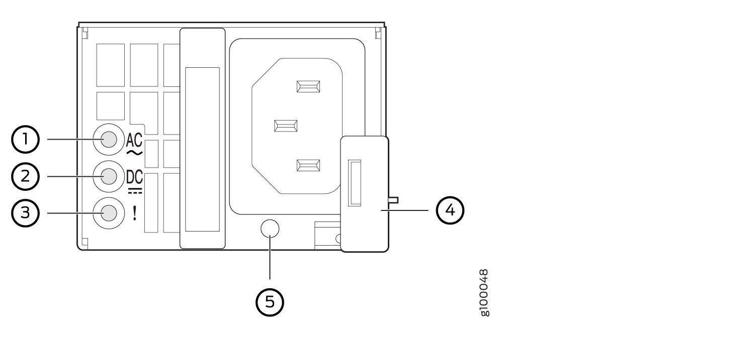
Power Cord Retainer Port on the AC Power Supply Module
      1

    Input status LED

      4

    Ejector lever

      2

    Output status LED

      5

    AC power cord retainer port

      3

    Fault LED


    Figure 4 shows the power cord retainer installed on the AC power supply module.

    Figure 4: Power Cord Retainer Installed on the AC Power Supply Module
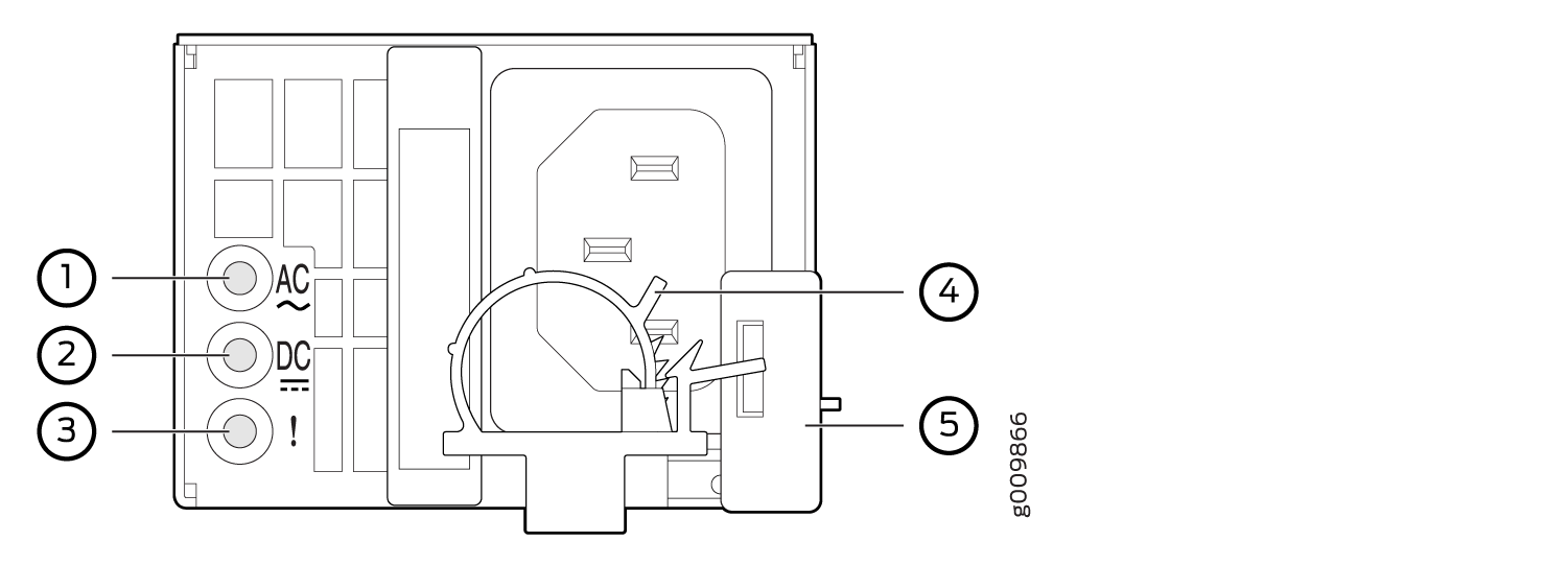
Power Cord Retainer Installed on the AC Power Supply Module
      1

    Input status LED

      4

    AC power cord retainer installed

      2

    Output status LED

      5

    Ejector lever

      3

    Fault LED

     
  6. Press the small tab on the retainer strip to loosen the loop. Slide the loop until you have enough space to insert the power cord coupler into the inlet.
  7. Insert the power cord coupler firmly into the inlet.
  8. Slide the loop toward the power supply until it is snug against the base of the coupler.
  9. Press the tab on the loop and draw out the loop into a tight circle (see Figure 5).
  10. Route the power cord appropriately. Verify that the power cord does not block the air exhaust and access to router components, or drape where people could trip on it.
  11. Power on the power supply at source.
  12. Repeat Step 1 through Step 10 for the installing the remaining power supply.
Figure 5: Connecting AC Power to the RouterConnecting AC Power to the Router

Powering On an AC-Powered MX204 Router

To power on an AC-powered router:

  1. Verify that the power supply modules are fully inserted in the chassis.
  2. Verify that each AC power cord is securely inserted into its appliance inlet.
  3. Verify that an external management device is connected to the CON port on the chassis.
  4. Turn on power to the external management device.
  5. Switch on the dedicated customer-site circuit breakers for the power supply modules. Follow the instructions for your site.
  6. Attach an ESD grounding strap to your bare wrist and connect the strap to one of the ESD points on the chassis.
  7. Observe the status LED on each power supply faceplate. If an AC power supply is correctly installed and functioning normally, the status LED on the router beside the AC power supply lights steadily green.

    If the status LED on the power supply is lit red, the power supply is not functioning normally. Repeat the installation and cabling procedures.

    Note:

    After you power off a power supply, wait at least 60 seconds before you turn it back on. Likewise, after you power on a power supply, wait at least 60 seconds beforeyou turn it off.

    If the system is completely powered off when you power on the power supply, the Routing Engine (or RCB) boots as the power supply completes its startup sequence. If the Routing Engine finishes booting and you need to power off the system again, first issue the CLI request system halt command.

    After a power supply is powered on, it can take up to 60 seconds for status indicators—such as the status LEDs on the power supply and the show chassis command display—to indicate that the power supply is functioning normally. Ignore error indicators that appear during the first 60 seconds.

  8. On the external management device connected to the Routing Engine, monitor the startup process to verify that the system has booted properly.

Connecting Power to a DC-Powered MX204 Router

CAUTION:

Do not mix AC and DC power supply modules within the same device. Mixing currents can damage the device.

Warning:

Before you perform DC power procedures, ensure there is no power to the DC circuit. To ensure that all power is off, locate the circuit breaker on the panel board that services the DC circuit, switch the circuit breaker to the off position, and tape the switch handle of the circuit breaker in the off position.

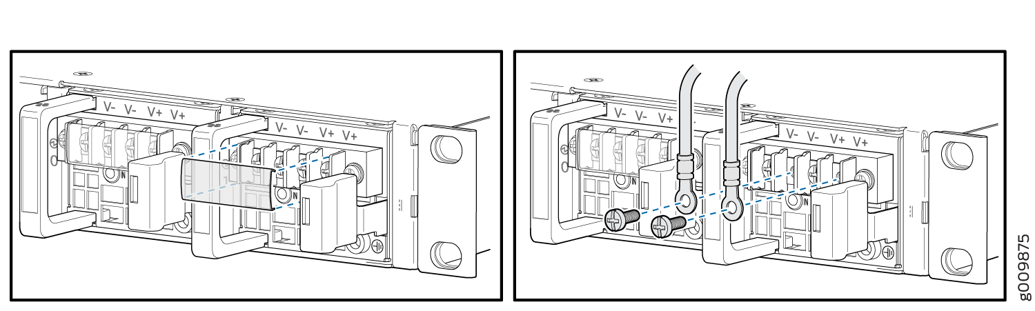
You connect DC power to the router by attaching power cables from the external DC power sources to the terminal on the power supply faceplate. You must provide the power cables (the cable lugs are supplied with the router). For power cable specifications, see DC Power Cable Specifications for MX204 Router.

To connect the DC source power cables to the router for each power supply:

  1. Switch off the dedicated customer-site circuit breakers. Ensure that the voltage across the DC power source cable leads is 0 V and that there is no chance that the cable leads might become active during installation.
  2. Attach an ESD grounding strap to your bare wrist, and connect the other end of the strap to an ESD grounding point.
  3. Verify that the DC power cables are correctly labeled before making connections to the power supply. In a typical power distribution scheme where the return is connected to chassis ground at the battery plant, you can use a multimeter to verify the resistance of the –48V and RTN DC cables to chassis ground:
    • The cable with very large resistance (indicating an open circuit) to chassis ground is –48V.

    • The cable with very low resistance (indicating a closed circuit) to chassis ground is RTN.

    CAUTION:

    You must ensure that power connections maintain the proper polarity. The power source cables might be labeled (+) and (–) to indicate their polarity. There is no standard color coding for DC power cables. The color coding used by the external DC power source at your site determines the color coding for the leads on the power cables that attach to the terminal studs on each power supply.

  4. Install heat-shrink tubing insulation around the power cables.

    To install heat-shrink tubing:

    1. Slide the tubing over the portion of the cable where it is attached to the lug barrel. Ensure that tubing covers the end of the wire and the barrel of the lug attached to it.

    2. Shrink the tubing with a heat gun. Ensure that you heat all sides of the tubing evenly so that it shrinks around the cable tightly.

    Figure 6 shows the steps to install heat-shrink tubing.

    Note:

    Do not overheat the tubing.

    Figure 6: How to Install Heat-Shrink Tubing
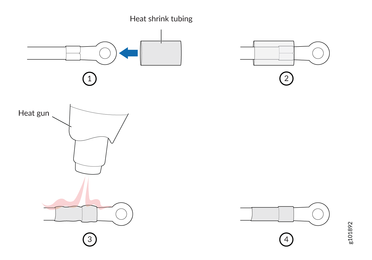
 How to Install Heat-Shrink Tubing
  5. Remove the screws from the terminals.
  6. Secure each power cable lug to the terminal with the screws (see Figure 7). Apply between 5 lb-in. (0.6 Nm) and 6 lb-in. (0.7 Nm) of torque to the screws. Do not overtighten the screws. (Use a socket nut driver.)
    1. Secure the positive (+) DC source power cable lug to the RTN (return) terminal.

    2. Secure the negative (–) DC source power cable lug to the –48V (input) terminal.

    CAUTION:

    Ensure that each power cable lug seats flush against the surface of the terminal block as you are tightening the screws. Ensure that each nut is properly threaded into the terminal. Applying installation torque to the screws when improperly threaded can result in damage to the terminal.

    CAUTION:

    You must ensure that power connections maintain the proper polarity. The power source cables might be labeled (+) and (–) to indicate their polarity. There is no standard color coding for DC power cables. The color coding used by the external DC power source at your site determines the color coding for the leads on the power cables that attach to the terminal studs on each power supply.

    Note:

    For information about connecting to DC power sources, see MX204 Router DC Power Specifications.

  7. Verify that the power cables are connected correctly, that they do not touch or block access to router components, and that they do not drape where people could trip on them.
  8. Repeat Step 1 through Step 7 for installing the other power supply modules.
Figure 7: Connecting DC Power to the RouterConnecting DC Power to the Router

Powering On a DC-Powered MX204 Router

To power on a DC-powered router:

  1. Verify that an external management device is connected to the CON port on the chassis.
  2. Turn on power to the external management device.
  3. Verify that the power supply modules are fully inserted in the chassis.
  4. Verify that the source power cables are connected to the appropriate terminal: the positive (+) source cable to the return terminal (labeled RTN) and the negative (–) source cable to the input terminal (labeled –48V).
  5. Switch on the dedicated customer-site circuit breakers to provide power to the DC power cables.
  6. Check that the status LED on the power supply faceplate is lit steadily green to verify that power is present.
  7. If power is not present:
    • Verify that the fuse is installed correctly, and turn on the breaker at the battery distribution fuse board or fuse bay.

    • Check the voltage with a meter at the terminals of the power supply for correct voltage level and polarity.

  8. Attach an ESD grounding strap to your bare wrist, and connect the other end of the strap to an ESD grounding point.
  9. Observe the status LED on each power supply faceplate. If a DC power supply is correctly installed and functioning normally, the status LED lights green steadily.

    If the status LED on the power supply is unlit, the power supply is not functioning normally. Repeat the installation and cabling procedures.

    Note:

    After you power off a power supply, wait at least 60 seconds before you turn it back on. Likewise, after you power on a power supply, wait at least 60 seconds beforeyou turn it off.

    If the system is completely powered off when you power on the power supply, the Routing Engine (or RCB) boots as the power supply completes its startup sequence. If the Routing Engine finishes booting and you need to power off the system again, first issue the CLI request system halt command.

    After a power supply is powered on, it can take up to 60 seconds for status indicators—such as the status LEDs on the power supply and the show chassis command display—to indicate that the power supply is functioning normally. Ignore error indicators that appear during the first 60 seconds.

  10. On the external management device connected to the Routing Engine, monitor the startup process to verify that the system has booted properly.

Powering Off the MX204 Router

Before you power off an MX204:

  • Ensure that you have taken the necessary precautions to prevent electrostatic discharge (ESD) damage. See Prevention of Electrostatic Discharge Damage.

  • Ensure that you do not need to route traffic through the MX204.

  • Ensure that you have the following parts and tools available to power off the MX204:

    • An ESD grounding strap

    • An external management device such as a PC

    • An RJ-45 to DB-9 rollover cable to connect the external management device to the console port

Note:

After powering off a power supply, wait at least 60 seconds before turning it back on.

To power off the router:

  1. Connect a management device to the console (see Connecting the MX204 Router to External Devices and Cables).
  2. On the external management device connected to the Routing Engine, issue the request system halt command.

    You see the following output (or something similar) after entering the command:

  3. Wait until a message appears on the console confirming that the operating system has halted. For more information about the command, see the CLI Explorer.
  4. Attach an ESD grounding strap to your bare wrist, and connect the other end of the strap to an ESD grounding point.
  5. Switch off the power supply source.