Connecting the MX204 to the Network
Tools and Parts Required to Connect the MX204 Router to External Devices
To connect the router to external devices, you need the following tools and parts:
2.5-mm flat-blade (–) screwdriver for the alarm relay contacts
Electrostatic discharge (ESD) grounding wrist strap (provided in the accessory kit)
See Also
Connecting the MX204 Router to External Devices and Cables
Figure 1 shows the front panel of the MX204 router. All the connections to the router are made through the front panel.
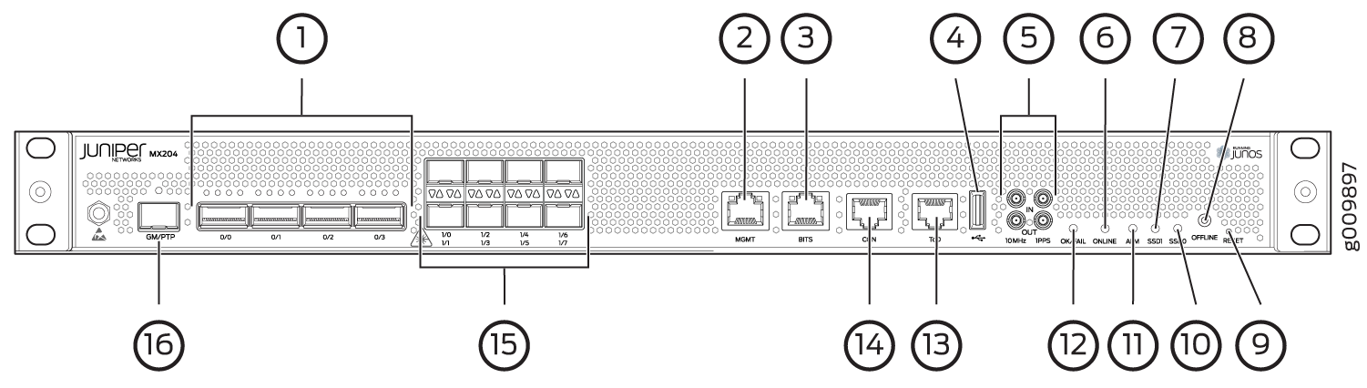
1 — Rate-selectable ports | 9 — RESET button |
2 — Management (MGMT) port | 10 — SSD0 LED |
3 — BITS port with LEDs | 11 — Alarm (ALM) LED |
4 — USB port | 12 — OK/FAIL LED |
5 — 1PPS and 10MHz GPS input and output ports | 13 — Time of day (ToD) port with LEDs |
6 — ONLINE LED | 14 — Console (CON) port |
7 — SSD1 LED | 15 — 10-Gigabit Ethernet SFP+ ports |
8 — OFFLINE button | 16 — PTP grandmaster clock (GM/PTP) port |
- Connecting the Router to a Network for Out-of-Band Management
- Connecting the Router to a Console Device
- Connecting the Router to External Clocking and Timing Devices
Connecting the Router to a Network for Out-of-Band Management
To connect the router to a network for out-of-band management, connect an Ethernet cable with RJ-45 connectors to the MGMT port on the router.
Use shielded CAT5e cable for the CON and MGMT ports on the chassis.
To connect to the MGMT port on the router faceplate:
- Turn off power to the management device.
- Plug one end of the Ethernet cable (Figure 2 shows the connector) into the MGMT port on the router.
- Plug the other end of the cable into the network device.
|
Callout |
Label |
Description |
|---|---|---|
|
2 (See Figure 1) |
MGMT |
Dedicated management channel for device maintenance. It is also used by system administrators to monitor and manage the router remotely. |
Connecting the Router to a Console Device
To use a system console to configure and manage the router, connect it to the appropriate CON port on the router. The console port is used to connect a laptop or console terminal to configure the router (see Figure 4 and Figure 5). The console port accepts a cable with an RJ-45 connector.
Use shielded CAT5e cable for connecting the CON and MGMT ports on the MX204 router.
To connect a management console:


|
Callout |
Label |
Description |
|---|---|---|
|
14 (See Figure 1) |
CON |
Connect a laptop or console terminal to configure the router. |
Connecting the Router to External Clocking and Timing Devices
The router supports external clock synchronization for Synchronous Ethernet, and external inputs.
- Connecting 1-PPS and 10-MHz Timing Devices to the Router
- Connecting a Time-of-Day Device to the Router
- Connecting a BITS External Clocking Device to the Router
Connecting 1-PPS and 10-MHz Timing Devices to the Router
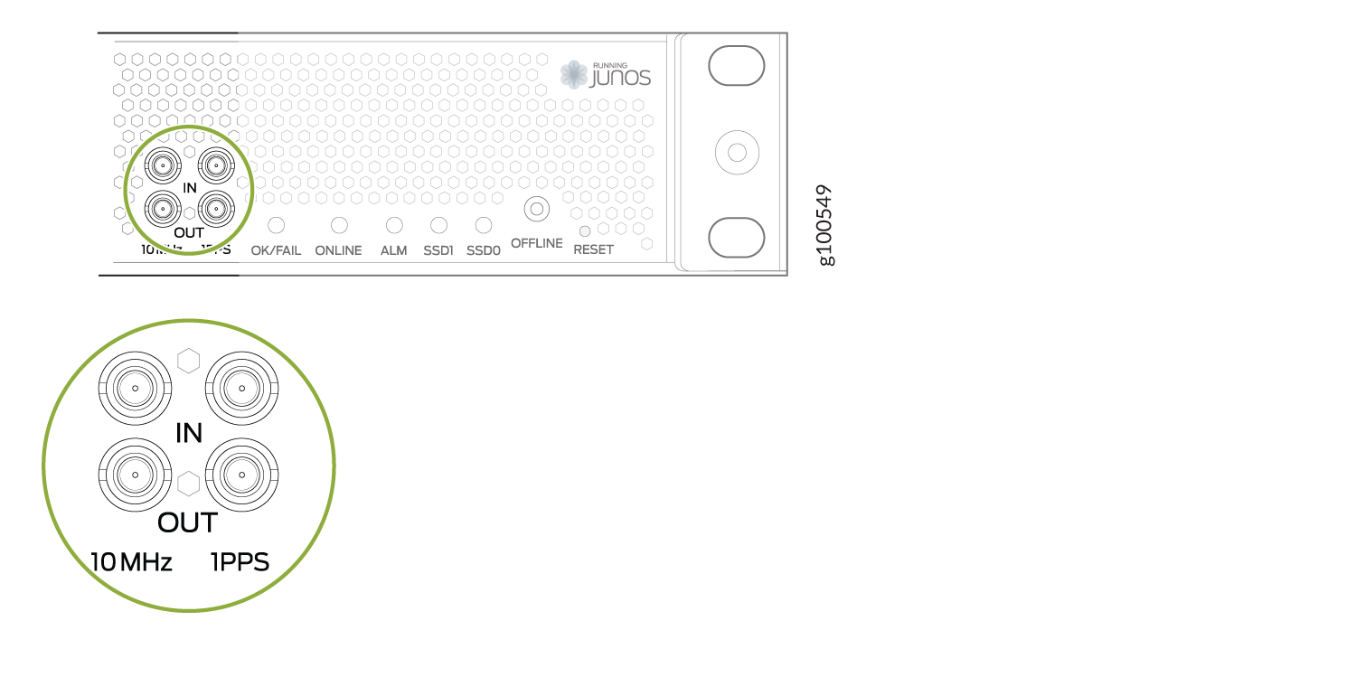
The router has two 2x1 DIN 1.0/2.3 right angle connectors that support 1-PPS-IN, 1-PPS-OUT, 10-MHz-IN, and 10-MHz-OUT timing ports.
MX204 can be configured as a timing primary or a client device. If the MX204 is configured as a timing primary device, the router gets 1-PPS-IN and 10-MHz-IN input (connected to the ports marked IN) from the timing source and sends 1-PPS-OUT and 10-MHz-OUT to a client device. If the MX204 is configured as a timing client device, it receives 1-PPS-IN and 10-MHz-IN (connected to ports marked IN) as input from the timing source.
Ensure a cable of 3 m or less in length is used for the 10-MHz and 1-PPS connectors.
To connect the DIN cable to the external clocking device:
|
Label |
Description |
|---|---|
|
10MHz-IN 1PPS-IN |
1 PPS input port 10 MHz input port |
|
10MHz-OUT 1PPS-OUT |
1 PPS output port 10 MHz output port |
Connecting a Time-of-Day Device to the Router
A time-of-day port, labeled ToD, on the front panel of the router enables you to connect external timing devices.
To connect the router to a ToD external timing device:
- Attach an electrostatic discharge (ESD) grounding trap on your bare wrist, and connect the strap to one of the ESD points on the chassis.
- Plug one end of the RJ-45 cable into the ToD port on the front panel of the router.
- Plug the other end of the RJ-45 cable into the ToD timing device.
- Verify that the LEDs for the ToD port on the router are lit steadily green.
- Configure the port. See Configuring Clock Synchronization Interface on MX Series Routers.
|
Callout |
Label |
Description |
|---|---|---|
|
13 (See Figure 1) |
ToD |
ToD RJ-45 port with LED. |
Connecting a BITS External Clocking Device to the Router
The router has an external building-integrated timing supply (BITS) port, labeled BITS, on the front panel of the router.
To connect the router to a BITS external clocking device:
- Attach an electrostatic discharge (ESD) grounding trap on your bare wrist, and connect the strap to one of the ESD points on the chassis.
- Plug one end of the RJ-45 cable into the internal clock port on the craft interface.
- Plug the other end of the RJ-45 cable into the BITS external clocking device.
- Verify that the LEDs for the BITS port are lit steadily green.
- Configure the port. See Configuring Clock Synchronization Interface on MX Series Routers.
|
Callout |
Label |
Description |
|---|---|---|
|
3 (See Figure 1) |
BITS |
Building-Integrated Timing Supply (BITS) clock interface port with LED. |