MX204 Cooling System
MX204 Cooling System Description
The cooling system components work together to keep all router components within the acceptable temperature range.
The cooling system consists of the following features and components:
Fan Trays
The chassis monitors the temperature of the router components. When the router is operating normally, the fans function at lower than full speed. If a fan fails or the ambient temperature rises above a threshold, the speed of the remaining fans is automatically adjusted to keep the temperature within the acceptable range. If the ambient maximum temperature specification is exceeded and the system cannot be adequately cooled, the Routing Engine shuts down the system by disabling output power from each power supply.
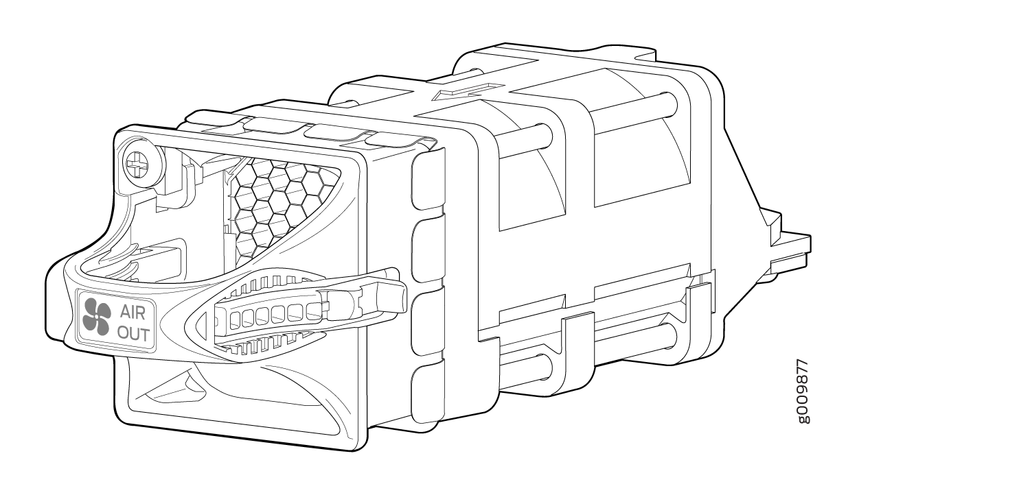
The router has three fan modules (or fan trays) that install in the rear of the router. Each fan modules contain one counter-rotating fan. The fan modules are hot-insertable and hot-removable field-replaceable units (FRUs) (see Figure 1).
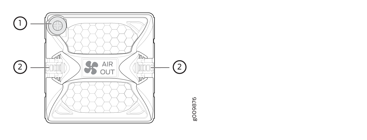
1 — Captive screw | 2 — Latch |
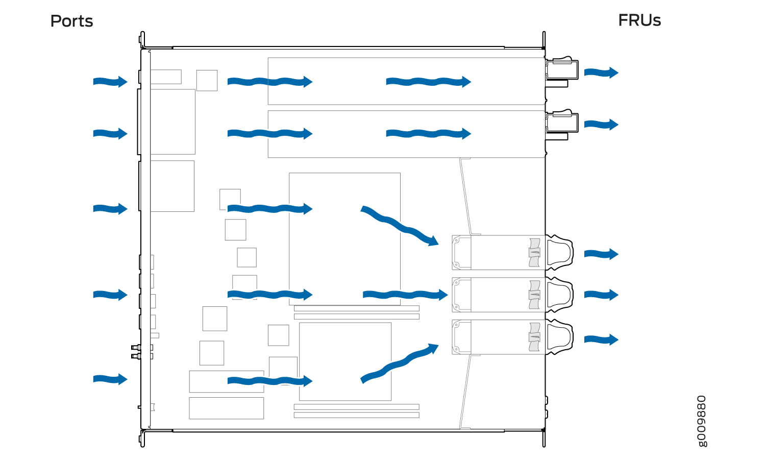
Airflow
The router has front-to-back (AIR OUT) cooling system (see Figure 2). Air is pulled through the front the chassis toward the fan tray, where it is exhausted out of the system.
Power Supply Cooling System
The power supply modules are self-cooling and are located in the rear of the router. Each power supply module has it’s own built-in fan that cools the power supply module. The exhaust for the power supply modules are also located on the rear of the chassis.
See Also
MX204 Fan Status LED
The MX204 fan module does not have any LED—the fan status LEDs are located on the MX204 chassis. Figure 3 shows the fan status LEDs.
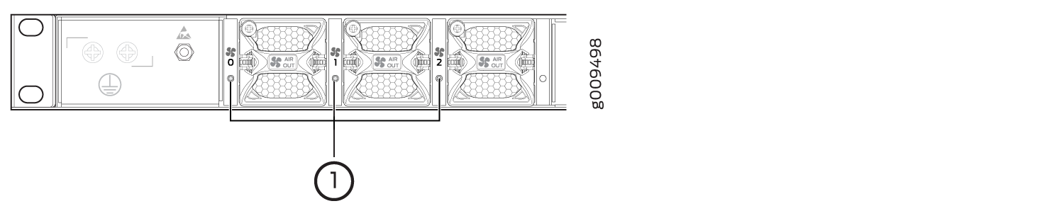
1 — Fan status LEDs |
The fan status LED is a bicolor LED. Table 1 describes the behavior of the fan status LED.
|
Color |
State |
Description |
|---|---|---|
|
Green |
Blinking |
Fan module hardware initialization is complete and software initialization is pending. |
|
On steadily |
Software initialization is complete and the fan is functioning normally. |
|
|
Red |
On steadily |
Fan module is faulty and not functioning normally. |
|
– |
Off |
Fan module not present |