Auto Discovery VPNs
Learn about Auto Discovery VPN and how to configure the feature on the firewall.
Auto Discovery VPN (ADVPN) dynamically establishes VPN tunnels between spokes to avoid routing traffic through the hub.
Use Feature Explorer to confirm platform and release support for specific features.
Review the Platform-Specific Multicast in ADVPN Behavior section for notes related to your platform.
Understanding Auto Discovery VPN
Auto Discovery VPN (ADVPN) is a technology that allows the central Hub to dynamically inform spokes about a better path for traffic between two spokes. When both spokes acknowledge the information from the Hub, they establish a shortcut tunnel and change the routing topology for the host to reach the other side without sending traffic through the Hub.
- ADVPN Protocol
- Establishing a Shortcut
- Shortcut Initiator and Responder Roles
- Shortcut Attributes
- Shortcut Termination
- Multicast Support Using PIM
- ADVPN Configuration Limitations
ADVPN Protocol
ADVPN uses an extension of IKEv2 protocol to exchange messages between two peers,
that allows the spokes to establish a shortcut tunnel between each other. Devices
that support the ADVPN extension send an ADVPN_SUPPORTED
notification in the IKEv2 Notify payload including its capability information
and the ADVPN version number during the initial IKE exchange. A device that supports
ADVPN can act as either a shortcut suggester or a shortcut partner, but
not both.
Establishing a Shortcut
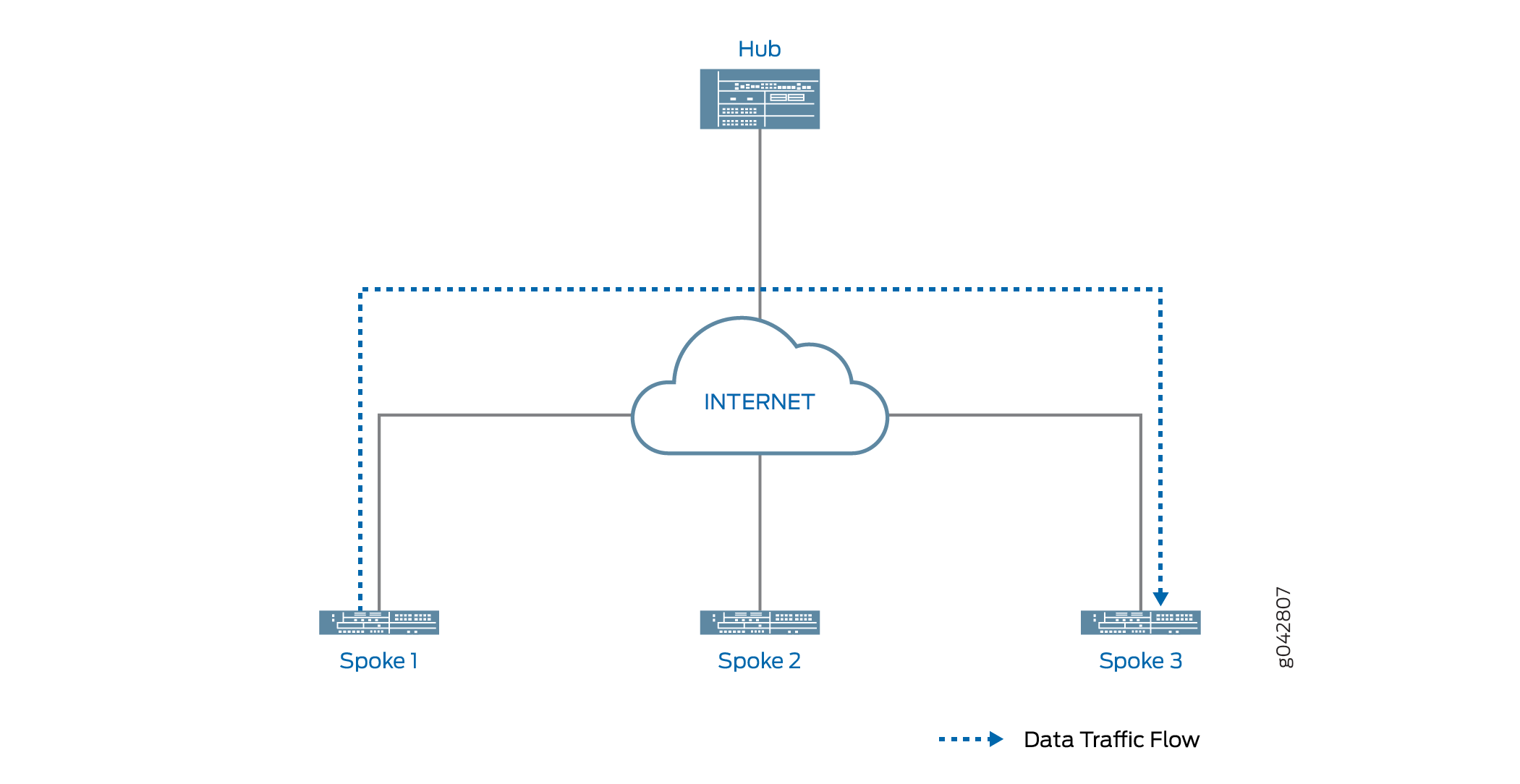
An IPsec VPN gateway can act as a shortcut suggester when it notices that traffic is exiting a tunnel with one of its peers and entering a tunnel with another peer. Figure 1 shows traffic from Spoke 1 to Spoke 3 passing through the Hub.
When ADVPN is configured on the devices, ADVPN shortcut capability information is exchanged between the hub and the spokes. As long as Spokes 1 and 3 have previously advertised ADVPN shortcut partner capability to the Hub, the Hub can suggest that Spokes 1 and 3 establish a shortcut between each other.
The shortcut suggester uses its already established IKEv2 SAs with the peers to begin a shortcut exchange with one of the two peers. If the peer accepts the shortcut exchange, then the shortcut suggester begins a shortcut exchange with the other peer. The shortcut exchange includes information to allow the peers (referred to as shortcut partners) to establish IKE and IPsec SAs with each other. The creation of the shortcut between the shortcut partners starts only after both peers accept the shortcut exchange.
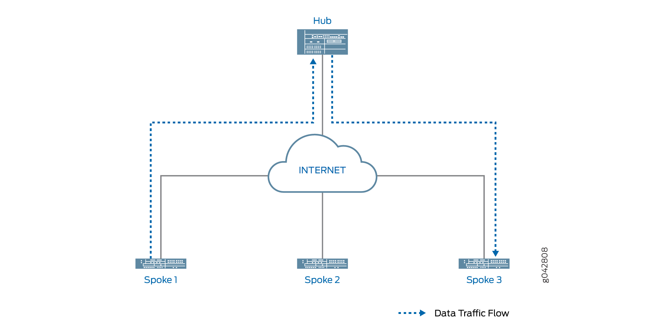
Figure 2 shows traffic passing through a shortcut between Spokes 1 and 3. Traffic from Spoke 1 to Spoke 3 does not need to traverse the Hub.
Shortcut Initiator and Responder Roles
The shortcut suggester chooses one of the shortcut partners to act as the initiator for the shortcut; the other partner acts as the responder. If one of the partners is behind a NAT device, then the partner behind the NAT device is chosen as the initiator. If none of the partners is behind a NAT device, the suggester randomly chooses one of the partners as the initiator; the other partner acts as the responder. If both partners are behind NAT devices, then a shortcut cannot be created between them; the suggester does not send a shortcut exchange to any of the peers.
The shortcut suggester begins the shortcut exchange with the responder first. If the responder accepts the shortcut suggestion, then the suggester notifies the initiator.
Using information contained in the shortcut suggester’s notification, the shortcut initiator establishes an IKEv2 exchange with the responder, and a new IPsec SA is established between the two partners. On each partner, the route to the network behind its partner now points to the shortcut instead of to the tunnel between the partner and the suggester. Traffic originating behind one of the partners that is destined to a network behind the other shortcut partner flows over the shortcut.
If the partners decline the shortcut suggestion, then the partners notify the suggester with the reason for the rejection. In this case, traffic between the partners continues to flow through the shortcut suggester.
Shortcut Attributes
The shortcut receives some of its attributes from the shortcut suggester while other attributes are inherited from the suggester-partner VPN tunnel configuration. Table 1 shows the parameters of the shortcut.
|
Attributes |
Received/Inherited From |
|---|---|
|
ADVPN |
Configuration |
|
Antireplay |
Configuration |
|
Authentication algorithm |
Configuration |
|
Dead peer detection |
Configuration |
|
DF bit |
Configuration |
|
Encryption algorithm |
Configuration |
|
Establish tunnels |
Suggester |
|
External interface |
Configuration |
|
Gateway policy |
Configuration |
|
General IKE ID |
Configuration |
|
IKE version |
Configuration |
|
Install interval |
Configuration |
|
Local address |
Configuration |
|
Local identity |
Suggester |
|
NAT traversal |
Configuration |
|
Perfect forward secrecy |
Configuration |
|
Protocol |
Configuration |
|
Proxy ID |
Not applicable |
|
Remote address |
Suggester |
|
Remote identity |
Suggester |
|
Respond bad SPI |
Configuration |
|
Traffic selector |
Not applicable |
Shortcut Termination
By default, the shortcut lasts indefinitely. Shortcut partners terminate the shortcut
if traffic falls below a specified rate for a specified time. By default, the
shortcut gets terminated if traffic falls below 5 packets per second for 300
seconds; the idle time and idle threshold values are configurable for partners. You
can manually delete the shortcut on either shortcut partner with the clear
security ike security-association or clear security ipsec
security-association commands to clear the corresponding IKE or IPsec
SA. Either of the shortcut partners can terminate the shortcut at any time by
sending an IKEv2 delete payload to the other shortcut partner.
When the shortcut is terminated, the corresponding IKE SA and all child IPsec SAs are deleted. After the shortcut is terminated, the corresponding route is deleted on both shortcut partners and traffic between the two peers again flows through the suggester. Shortcut termination information is sent from a partner to the suggester.
The lifetime of a shortcut is independent of the tunnel between the shortcut suggester and shortcut partner. The shortcut is not terminated simply because the tunnel between the suggester and partner is terminated.
Multicast Support Using PIM
The firewalls support Protocol Independent Multicast (PIM) in point-to-multipoint (P2MP) mode in ADVPN infrastructure. You can enable PIM on the firewall's secure tunnel interface, st0, with P2MP mode. The support for multicast traffic using PIM in ADVPN is similar to the support provided in AutoVPN. ADVPN follows same considerations as AutoVPN when configuring multicast support. For more details on understanding multicast support using PIM on P2MP infrastructure, see Understand AutoVPN. To enable PIM on st0 P2MP interface:
-
In Multinode High Availability environment, P2MP multicast is achieved using node-local tunnels. The routing protocol over the st0 interface doesn't support synced-state tunnel. See IPsec VPN Support in Multinode High Availability.
One of the firewalls is a shortcut suggester and rest of the firewalls are shortcut partners. Typically, the multicast sender resides behind the shortcut suggester, while the multicast receivers are behind the shortcut partners. For multicast support, the secure tunnel interface, st0, on the suggester and the partner devices are configured with PIM P2MP mode. On each of these devices, the st0 P2MP interface tracks all PIM joins per neighbor to ensure that the multicast forwarding or replication happens only to those neighbors that are in joined state.
The firewalls support IP multicast traffic in PIM sparse mode over the st0 P2MP interface. The suggester acts as the first-hop router (FHR) or the rendezvous point (RP). The partners can act as the last-hop routers (LHR) in the P2MP network. The devices in the network replicate the multicast data packets to neighbors that join the multicast group.
For details on how to configure PIM on P2MP infrastructure, see Configure Multicast Support on P2MP Infrastructure.
ADVPN Configuration Limitations
Note the following limitations when configuring ADVPN:
-
ADVPN is only supported for site-to-site communications. Configuring an ADVPN suggester is only allowed on AutoVPN hubs.
-
You cannot configure both suggester and partner roles. When ADVPN is enabled on a gateway, you cannot disable both suggester and partner roles on the gateway.
-
You cannot create a shortcut between partners that are both behind NAT devices. The suggester can initiate a shortcut exchange only if one of the partners is behind a NAT device or if no partners are behind NAT devices.
- To use an IPv6 address for ADVPN:
-
You must configure the st0 interface with P2MP support on all the hub and spoke devices.
-
You must run dynamic routing protocols (DRPs) such as the OSPFv3 to update the routing preference to shortcut tunnel over static tunnel.
-
Note that you cannot configure the VPN monitor feature with IPv6 P2MP st0 interface based ADVPN.
-
-
You can run the ADVPN service with a DRP that supports either the IPv6 address or IPv4 address but not both at the same time.
-
For configuration changes on the partner, such as enable, disable or role change, the iked:
-
Tears down and renegotiates the static IKE SA and the IPsec SA to exchange the new capability.
-
Cleans the shortcut IKE SA and the IPsec SA, and the suggestion information that exists.
-
-
For non-ADVPN configuration changes, such as:
-
The static tunnel configuration change that leads to clearing of both the static IKE SA and the IPsec SA, the iked tears down the shortcut IKE SA and the IPsec SA. The iked cleans the suggestion information. The shortcut tunnel doesn't renegotiate again, until it receives shortcut suggestion from the suggester.
-
The static tunnel configuration change that leads to clearing of the static tunnel IPsec SA only, the iked tears down the shortcut IKE SA and the IPsec SA. The iked cleans the suggestion information. The shortcut tunnel doesn't renegotiate again, until it receives shortcut suggestion from the suggester.
-
We do not support the following configurations with ADVPN with both the kmd and the iked processes:
-
IKEv1
-
Policy-based VPN
-
IKEv2 configuration payload
-
Traffic selectors
-
Point-to-point secure tunnel interfaces
-
Seeded preshared key
-
Shared preshared key—No support with kmd process
Understanding Traffic Routing with Shortcut Tunnels
Tunnel flaps or catastrophic changes can cause both static tunnels and shortcut tunnels to go down. When this happens, traffic to a specific destination might be routed through an unexpected shortcut tunnel instead of through an expected static tunnel.
In Figure 3, static tunnels exist between the hub and each of the spokes. OSPF adjacencies are established between the hub and spokes. Spoke A also has a shortcut tunnel with Spoke B and OSPF adjacencies are established between the spokes. The hub (the shortcut suggester) recognizes that if connectivity between the hub and Spoke A goes down, Spoke A’s network can be reached through the shortcut tunnel between Spoke B and Spoke A.
In Figure 4, the static tunnel between the hub and Spoke A is down. If there is new traffic from Spoke C to Spoke A, Spoke C forwards the traffic to the hub because it does not have a shortcut tunnel with Spoke A. The hub does not have an active static tunnel with Spoke A but it recognizes that there is a shortcut tunnel between Spoke A and Spoke B, so it forwards the traffic from Spoke C to Spoke B.
As long as both Spoke B and Spoke C support Auto Discovery VPN (ADVPN) partner capability, the hub can suggest that the spokes establish a direct shortcut between each other. This occurs even though there is no direct traffic between the two spokes. Traffic from Spoke C to Spoke A travels through the shortcut tunnel between Spoke C and Spoke B, and then through the shortcut tunnel between Spoke B and Spoke A (see Figure 5).
When the static tunnel between the hub and Spoke A is reestablished, the tunnel is advertised to all spokes. Spoke C learns that there is a better route to reach Spoke A; instead of passing traffic through Spoke B, it forwards traffic for Spoke A to the hub. The hub suggests that a shortcut tunnel be established between Spoke C and Spoke A. When the shortcut tunnel is established between Spoke C and Spoke A, traffic flows through the shortcut tunnel (see Figure 6). Traffic between Spoke C and Spoke A no longer travels through Spoke B, and the shortcut tunnel between Spoke B and Spoke C eventually disappears.
You can use the connection-limit option at the [edit security ike gateway gateway-name advpn
partner] hierarchy level to set the maximum number of shortcut
tunnels that can be created with different shortcut partners using
a particular gateway. The maximum number, which is also the default,
is platform-dependent.
Example: Improving Network Resource Utilization with Auto Discovery VPN Dynamic Tunnels
If you are deploying an AutoVPN network, you might be able to increase your network resource utilization by configuring Auto Discovery VPN (ADVPN). In AutoVPN networks, VPN traffic flows through the hub even when the traffic is travelling from one spoke to another. ADVPN allows VPN tunnels to be established dynamically between spokes, which can result in better network resource utilization. Use this example to configure ADVPN to enable dynamic spoke-to-spoke VPN tunnels in your AutoVPN network.
Requirements
This example uses the following hardware and software components:
Three supported firewalls as AutoVPN hub and spokes.
Junos OS Release that support ADVPN.
Digital certificates enrolled in the hub and spokes that allow the devices to authenticate each other.
Before you begin:
Obtain the address of the certificate authority (CA) and the information they require (such as the challenge password) when you submit requests for local certificates.
Enroll the digital certificates in each device.
See Enroll Certificate.
This example uses the OSPF dynamic routing protocol as well as static route configurations to forward packets through VPN tunnels. You should be familiar with the OSPF dynamic routing protocol that is used to forward packets through the VPN tunnels.
Overview
This example shows the configurations of an AutoVPN hub and
two spokes for ADVPN. The spokes establish IPsec VPN connections to
the hub, which allows them to communicate with each other as well
as to access resources on the hub. While traffic is initially passed
from one spoke to the other through the hub, ADVPN allows the spokes
to establish a direct security association between each other. The
hub acts as the shortcut suggester. On the hub, the ADVPN configuration
disables the partner role. On the spokes, ADVPN configuration
disables the suggester role.
Certain Phase 1 and Phase 2 IKE tunnel options configured on the AutoVPN hub and spokes must have the same values. Table 2 shows the values used in this example.
Option |
Value |
|---|---|
IKE proposal: |
|
Authentication method |
rsa-signatures |
Diffie-Hellman (DH) group |
group5 |
Authentication algorithm |
sha1 |
Encryption algorithm |
aes-256-cbc |
IKE policy: |
|
Certificate |
local-certificate |
IKE gateway: |
|
Version |
v2-only |
IPsec proposal: |
|
Protocol |
esp |
Authentication algorithm |
hmac-sha1-96 |
Encryption algorithm |
aes-256-cbc |
IPsec policy: |
|
Perfect Forward Secrecy (PFS) group |
group5 |
The IKE gateway configuration on the hub and spokes include remote and local values that identify VPN peers. Table 3 shows the IKE gateway configuration for the hub and spokes in this example.
Option |
Hub |
Spokes |
|---|---|---|
Remote IP address |
Dynamic |
Spoke 1: 11.1.1.1 Spoke 2: 11.1.1.1 |
Local IP address |
11.1.1.1 |
Spoke 1: 21.1.1.2 Spoke 2: 31.1.1.2 |
Remote IKE ID |
Distinguished name (DN) with the string “XYZ” in the organization (O) field and “Sales” in the organization unit (OU) field in the spokes’ certificates |
DN with the string “Sales” in the OU field in the hub’s certificate |
Local IKE ID |
DN on the hub’s certificate |
DN on the spokes’ certificate |
The hub authenticates the spokes’ IKE ID if the subject fields of the spokes’ certificates contain the string “XYZ” in the O field and “Sales” in the OU field.
In this example, the default security policy that permits all traffic is used for all devices. More restrictive security policies should be configured for production environments.
Topology
Figure 7 shows the firewalls to be configured for this example.
Configuration
Configuring the Suggester (Hub)
CLI Quick Configuration
To quickly configure this example, copy the
following commands, paste them into a text file, remove any line breaks,
change any details necessary to match your network configuration,
copy and paste the commands into the CLI at the [edit] hierarchy
level, and then enter commit from configuration mode.
set interfaces ge-0/0/3 gigether-options redundant-parent reth0
set interfaces ge-0/0/4 gigether-options redundant-parent reth1
set interfaces ge-7/0/3 gigether-options redundant-parent reth0
set interfaces ge-7/0/4 gigether-options redundant-parent reth1
set interfaces reth0 redundant-ether-options redundancy-group 1
set interfaces reth0 unit 0 family inet address 10.1.1.1/24
set interfaces reth1 redundant-ether-options redundancy-group 1
set interfaces reth1 unit 0 family inet address 11.1.1.1/24
set interfaces st0 unit 1 multipoint
set interfaces st0 unit 1 family inet address 172.16.1.1/24
set protocols ospf graceful-restart restart-duration 300
set protocols ospf graceful-restart notify-duration 300
set protocols ospf graceful-restart no-strict-lsa-checking
set protocols ospf area 0.0.0.0 interface st0.1 interface-type p2mp
set protocols ospf area 0.0.0.0 interface st0.1 metric 10
set protocols ospf area 0.0.0.0 interface st0.1 retransmit-interval 1
set protocols ospf area 0.0.0.0 interface st0.1 dead-interval 40
set protocols ospf area 0.0.0.0 interface st0.1 demand-circuit
set protocols ospf area 0.0.0.0 interface st0.1 dynamic-neighbors
set protocols ospf area 0.0.0.0 interface reth0.0
set routing-options graceful-restart
set routing-options static route 21.1.1.0/24 next-hop 11.1.1.2
set routing-options static route 31.1.1.0/24 next-hop 11.1.1.2
set routing-options router-id 172.16.1.1
set security ike proposal IKE_PROP authentication-method rsa-signatures
set security ike proposal IKE_PROP dh-group group5
set security ike proposal IKE_PROP authentication-algorithm sha1
set security ike proposal IKE_PROP encryption-algorithm aes-256-cbc
set security ike policy IKE_POL proposals IKE_PROP
set security ike policy IKE_POL certificate local-certificate Suggester_Certificate_ID
set security ike gateway SUGGESTER_GW ike-policy IKE_POL
set security ike gateway SUGGESTER_GW dynamic distinguished-name wildcard O=XYZ, OU=Sales
set security ike gateway SUGGESTER_GW dynamic ike-user-type group-ike-id
set security ike gateway SUGGESTER_GW dead-peer-detection
set security ike gateway SUGGESTER_GW local-identity distinguished-name
set security ike gateway SUGGESTER_GW external-interface reth1.0
set security ike gateway SUGGESTER_GW local-address 11.1.1.1
set security ike gateway SUGGESTER_GW advpn partner disable
set security ike gateway SUGGESTER_GW advpn suggester
set security ike gateway SUGGESTER_GW version v2-only
set security ipsec proposal IPSEC_PROP protocol esp
set security ipsec proposal IPSEC_PROP authentication-algorithm hmac-sha1-96
set security ipsec proposal IPSEC_PROP encryption-algorithm aes-256-cbc
set security ipsec policy IPSEC_POL perfect-forward-secrecy keys group5
set security ipsec policy IPSEC_POL proposals IPSEC_PROP
set security ipsec vpn SUGGESTER_VPN bind-interface st0.1
set security ipsec vpn SUGGESTER_VPN ike gateway SUGGESTER_GW
set security ipsec vpn SUGGESTER_VPN ike ipsec-policy IPSEC_POL
set security pki ca-profile advpn ca-identity advpn
set security pki ca-profile advpn enrollment url http://10.157.92.176:8080/scep/advpn/
set security zones security-zone trust host-inbound-traffic system-services all
set security zones security-zone trust host-inbound-traffic protocols all
set security zones security-zone trust interfaces st0.1
set security zones security-zone trust interfaces reth0.0
set security zones security-zone untrust host-inbound-traffic system-services all
set security zones security-zone untrust host-inbound-traffic protocols all
set security zones security-zone untrust interfaces reth1.0
set security policies default-policy permit-all
Step-by-Step Procedure
The following example requires you to navigate various levels in the configuration hierarchy. For instructions on how to do that, see CLI User Guide.
To configure the suggester:
Configure interfaces.
[edit interfaces]
user@host# set ge-0/0/3 gigether-options redundant-parent reth0
user@host# set ge-0/0/4 gigether-options redundant-parent reth1
user@host# set ge-7/0/3 gigether-options redundant-parent reth0
user@host# set ge-7/0/4 gigether-options redundant-parent reth1
user@host# set reth0 redundant-ether-options redundancy-group 1
user@host# set reth0 unit 0 family inet address 10.1.1.1/24
user@host# set reth1 redundant-ether-options redundancy-group 1
user@host# set reth1 unit 0 family inet address 11.1.1.1/24
user@host# set st0 unit 1 multipoint
user@host# set st0 unit 1 family inet address 172.16.1.1/24
Configure the routing protocol and static routes.
[edit protocols ospf]
user@host# set graceful-restart restart-duration 300
user@host# set graceful-restart notify-duration 300
user@host# set graceful-restart no-strict-lsa-checking
user@host# set area 0.0.0.0 interface st0.1 interface-type p2mp
user@host# set area 0.0.0.0 interface st0.1 metric 10
user@host# set area 0.0.0.0 interface st0.1 retransmit-interval 1
user@host# set area 0.0.0.0 interface st0.1 dead-interval 40
user@host# set area 0.0.0.0 interface st0.1 demand-circuit
user@host# set area 0.0.0.0 interface st0.1 dynamic-neighbors
user@host# set area 0.0.0.0 interface reth0.0
[edit routing-options]
user@host# set graceful-restart
user@host# set static route 21.1.1.0/24 next-hop 11.1.1.2
user@host# set static route 31.1.1.0/24 next-hop 11.1.1.2
user@host# set router-id 172.16.1.1
Configure Phase 1 options.
[edit security ike proposal IKE_PROP]
user@host# set authentication-method rsa-signatures
user@host# set dh-group group5
user@host# set authentication-algorithm sha1
user@host# set encryption-algorithm aes-256-cbc
[edit security ike policy IKE_POL]
user@host# set proposals IKE_PROP
user@host# set certificate local-certificate Suggester_Certificate_ID
[edit security ike gateway SUGGESTER_GW]
user@host# set ike-policy IKE_POL
user@host# set dynamic distinguished-name wildcard O=XYZ, OU=Sales
user@host# set dynamic ike-user-type group-ike-id
user@host# set dead-peer-detection
user@host# set local-identity distinguished-name
user@host# set external-interface reth1.0
user@host# set local-address 11.1.1.1
user@host# set advpn partner disable
user@host# set advpn suggester
user@host# set version v2-only
Configure Phase 2 options.
[edit security ipsec proposal IPSEC_PROP]
user@host# set protocol esp
user@host# set authentication-algorithm hmac-sha1-96
user@host# set encryption-algorithm aes-256-cbc
[edit security ipsec policy IPSEC_POL]
user@host# set perfect-forward-secrecy keys group5
user@host# set proposals IPSEC_PROP
[edit security isec vpn SUGGESTER_VPN]
user@host# set bind-interface st0.1
user@host# set ike gateway SUGGESTER_GW
user@host# set ike ipsec-policy IPSEC_POL
Configure certificate information.
[edit security pki]
user@host# set ca-profile advpn ca-identity advpn
user@host# set ca-profile advpn enrollment url http://10.157.92.176:8080/scep/advpn/
Configure zones.
[edit security zones security-zone trust]
user@host# set host-inbound-traffic system-services all
user@host# set host-inbound-traffic protocols all
user@host# set interfaces st0.1
user@host# set interfaces reth0.0
[edit security zones security-zone untrust]
user@host# set host-inbound-traffic system-services all
user@host# set host-inbound-traffic protocols all
user@host# set interfaces reth1.0
Configure the default security policy.
[edit security policies]
user@host# set default-policy permit-all
Results
From configuration mode, confirm your configuration
by entering the show interfaces, show protocols, show routing-options, show security ike, show security ipsec, show security pki, show
security zones, and show security policies commands.
If the output does not display the intended configuration, repeat
the instructions in this example to correct the configuration.
[edit]
    user@host# show interfaces
    ge-0/0/3 {
        gigether-options {
            redundant-parent reth0;
        }
    }
    ge-0/0/4 {
        gigether-options {
            redundant-parent reth1;
        }
    }
    ge-7/0/3 {
        gigether-options {
            redundant-parent reth0;
        }
    }
    ge-7/0/4 {
        gigether-options {
            redundant-parent reth1;
        }
    }
    reth0 {
        redundant-ether-options {
            redundancy-group 1;
        }
        unit 0 {
            family inet {
                address 10.1.1.1/24;
            }
        }
    }
    reth1 {
        redundant-ether-options {
            redundancy-group 1;
        }
        unit 0 {
            family inet {
                address 11.1.1.1/24;
            }
        }
    }
    st0 {
        unit 1 {
            multipoint;
            family inet {
                address 172.16.1.1/24;
            }
        }
    }
    [edit]
    user@host# show protocols
    ospf {
        graceful-restart {
            restart-duration 300;
            notify-duration 300;
            no-strict-lsa-checking;
        }
        area 0.0.0.0 {
            interface st0.1 {
                interface-type p2mp;
                metric 10;
                retransmit-interval 1;
                dead-interval 40;
                demand-circuit;
                dynamic-neighbors;
            }
            interface reth0.0;
        }
    }
    [edit]
    user@host# show routing-options
    graceful-restart;
    static {
        route 21.1.1.0/24 next-hop 11.1.1.2;
        route 31.1.1.0/24 next-hop 11.1.1.2;
    }
    router-id 172.16.1.1;
    [edit]
    user@host# show security ike
    proposal IKE_PROP {
        authentication-method rsa-signatures;
        dh-group group5;
        authentication-algorithm sha1;
        encryption-algorithm aes-256-cbc;
    }
    policy IKE_POL {
        proposals IKE_PROP;
        certificate {
            local-certificate Suggester_Certificate_ID;
        }
    }
    gateway SUGGESTER_GW {
        ike-policy IKE_POL;
        dynamic {
            distinguished-name {
                wildcard O=XYZ, OU=Sales;
            }
            ike-user-type group-ike-id;
        }
        dead-peer-detection {
        }
        local-identity distinguished-name;
        external-interface reth1.0
        local-address 11.1.1.1;
        advpn {
            partner {
                disable;
                }
                suggester {
            ]
        }
        version v2-only;
    }
    [edit]
    user@host# show security ipsec
    proposal IPSEC_PROP {
        protocol esp;
        authentication-algorithm hmac-sha1-96;
        encryption-algorithm aes-256-cbc;
    }
    policy IPSEC_POL {
        perfect-forward-secrecy {
            keys group5;
        }
        proposals IPSEC_PROP;
    }
    vpn SUGGESTER_VPN {
        bind-interface st0.1;
        ike {
            gateway SUGGESTER_GW;
            ipsec-policy IPSEC_POL;
        }
    }
    [edit]
    user@host# show security pki
    ca-profile advpn {
        ca-identity advpn;
        enrollment {
            url http://10.157.92.176:8080/scep/advpn/;
        }
    }
    [edit]
    user@host# show security zones
    security-zone trust {
        host-inbound-traffic {
            system-services {
                all;
            }
            protocols {
                all;
            }
        }
        interfaces {
            st0.1;
            reth0.0;
        }
    }
    security-zone untrust {
        host-inbound-traffic {
            system-services {
                all;
            }
            protocols {
                all;
            }
        }
        interfaces {
            reth1.0;
        }
    }
    [edit]
user@host# show security policies
    default-policy {
        permit-all;
    }
If you are done configuring the device, enter commit from configuration mode.
Configuring the Partner (Spoke 1)
CLI Quick Configuration
To quickly configure this example, copy the
following commands, paste them into a text file, remove any line breaks,
change any details necessary to match your network configuration,
copy and paste the commands into the CLI at the [edit] hierarchy
level, and then enter commit from configuration mode.
set interfaces ge-0/0/3 gigether-options redundant-parent reth0
set interfaces ge-0/0/4 gigether-options redundant-parent reth1
set interfaces ge-7/0/3 gigether-options redundant-parent reth0
set interfaces ge-7/0/4 gigether-options redundant-parent reth1
set interfaces reth0 redundant-ether-options redundancy-group 1
set interfaces reth0 unit 0 family inet address 25.1.1.1/24
set interfaces reth1 redundant-ether-options redundancy-group 1
set interfaces reth1 unit 0 family inet address 21.1.1.2/24
set interfaces st0 unit 1 multipoint
set interfaces st0 unit 1 family inet address 172.16.1.2/24
set protocols ospf graceful-restart restart-duration 300
set protocols ospf graceful-restart notify-duration 300
set protocols ospf graceful-restart no-strict-lsa-checking
set protocols ospf area 0.0.0.0 interface st0.1 interface-type p2mp
set protocols ospf area 0.0.0.0 interface st0.1 metric 15
set protocols ospf area 0.0.0.0 interface st0.1 retransmit-interval 1
set protocols ospf area 0.0.0.0 interface st0.1 dead-interval 40
set protocols ospf area 0.0.0.0 interface st0.1 demand-circuit
set protocols ospf area 0.0.0.0 interface st0.1 dynamic-neighbors
set protocols ospf area 0.0.0.0 interface reth0.0
set routing-options graceful-restart
set routing-options static route 11.1.1.0/24 next-hop 21.1.1.1
set routing-options static route 31.1.1.0/24 next-hop 21.1.1.1
set routing-options router-id 172.16.1.2
set security ike proposal IKE_PROP authentication-method rsa-signatures
set security ike proposal IKE_PROP dh-group group5
set security ike proposal IKE_PROP authentication-algorithm sha1
set security ike proposal IKE_PROP encryption-algorithm aes-256-cbc
set security ike policy IKE_POL proposals IKE_PROP
set security ike policy IKE_POL certificate local-certificate Partner1_Certificate_ID
set security ike gateway PARTNER_GW ike-policy IKE_POL
set security ike gateway PARTNER_GW address 11.1.1.1
set security ike gateway PARTNER_GW local-identity distinguished-name
set security ike gateway PARTNER_GW remote-identity distinguished-name container OU=Sales
set security ike gateway PARTNER_GW external-interface reth1
set security ike gateway PARTNER_GW local-address 21.1.1.2
set security ike gateway PARTNER_GW advpn suggester disable
set security ike gateway PARTNER_GW advpn partner
set security ike gateway PARTNER_GW version v2-only
set security ipsec proposal IPSEC_PROP protocol esp
set security ipsec proposal IPSEC_PROP authentication-algorithm hmac-sha1-96
set security ipsec proposal IPSEC_PROP encryption-algorithm aes-256-cbc
set security ipsec policy IPSEC_POL perfect-forward-secrecy keys group5
set security ipsec policy IPSEC_POL proposals IPSEC_PROP
set security ipsec vpn PARTNER_VPN bind-interface st0.1
set security ipsec vpn PARTNER_VPN ike gateway PARTNER_GW
set security ipsec vpn PARTNER_VPN ike ipsec-policy IPSEC_POL
set security ipsec vpn PARTNER_VPN establish-tunnels immediately
set security pki ca-profile advpn ca-identity advpn
set security pki ca-profile advpn enrollment url http://10.157.92.176:8080/scep/advpn/
set security zones security-zone trust host-inbound-traffic system-services all
set security zones security-zone trust host-inbound-traffic protocols all
set security zones security-zone trust interfaces st0.1
set security zones security-zone trust interfaces reth0.0
set security zones security-zone untrust host-inbound-traffic system-services all
set security zones security-zone untrust host-inbound-traffic protocols all
set security zones security-zone untrust interfaces reth1.0
set security policies default-policy permit-all
Step-by-Step Procedure
The following example requires you to navigate various levels in the configuration hierarchy. For instructions on how to do that, see CLI User Guide.
To configure spoke 1:
Configure interfaces.
[edit interfaces]
user@host# set ge-0/0/3 gigether-options redundant-parent reth0
user@host# set ge-0/0/4 gigether-options redundant-parent reth1
user@host# set ge-7/0/3 gigether-options redundant-parent reth0
user@host# set ge-7/0/4 gigether-options redundant-parent reth1
user@host# set reth0 redundant-ether-options redundancy-group 1
user@host# set reth0 unit 0 family inet address 25.1.1.1/24
user@host# set reth1 redundant-ether-options redundancy-group 1
user@host# set reth1 unit 0 family inet address 21.1.1.2/24
user@host# set st0 unit 1 multipoint
user@host# set st0 unit 1 family inet address 172.16.1.2/24
Configure the routing protocol and static routes.
[edit protocols ospf]
user@host# set graceful-restart restart-duration 300
user@host# set graceful-restart notify-duration 300
user@host# set graceful-restart no-strict-lsa-checking
user@host# set area 0.0.0.0 interface st0.1 interface-type p2mp
user@host# set area 0.0.0.0 interface st0.1 metric 15
user@host# set area 0.0.0.0 interface st0.1 retransmit-interval 1
user@host# set area 0.0.0.0 interface st0.1 dead-interval 40
user@host# set area 0.0.0.0 interface st0.1 demand-circuit
user@host# set area 0.0.0.0 interface st0.1 dynamic-neighbors
user@host# set protocols ospf area 0.0.0.0 interface reth0.0
[edit routing-options]
user@host# set graceful-restart
user@host# set static route 11.1.1.0/24 next-hop 21.1.1.1
user@host# set static route 31.1.1.0/24 next-hop 21.1.1.1
user@host# set router-id 172.16.1.2
Configure Phase 1 options.
[edit security ike proposal IKE_PROP]
user@host# set authentication-method rsa-signatures
user@host# set dh-group group5
user@host# set authentication-algorithm sha1
user@host# set encryption-algorithm aes-256-cbc
[edit security ike policy IKE_POL]
user@host# set proposals IKE_PROP
user@host# set certificate local-certificate Partner1_Certificate_ID
[edit security ike gateway PARTNER_GW]
user@host# set ike-policy IKE_POL
user@host# set address 11.1.1.1
user@host# set local-identity distinguished-name
user@host# set remote-identity distinguished-name container OU=Sales
user@host# set external-interface reth1
user@host# set local-address 21.1.1.2
user@host# set advpn suggester disable
user@host# set advpn partner
user@host# set version v2-only
Configure Phase 2 options.
[edit security ipsec proposal IPSEC_PROP]
user@host# set protocol esp
user@host# set authentication-algorithm hmac-sha1-96
user@host# set encryption-algorithm aes-256-cbc
[edit security ipsec policy IPSEC_POL]
user@host# set perfect-forward-secrecy keys group5
user@host# set proposals IPSEC_PROP
[edit security isec vpn PARTNER_VPN]
user@host# set bind-interface st0.1
user@host# set ike gateway PARTNER_GW
user@host# set ike ipsec-policy IPSEC_POL
user@host# set establish-tunnels immediately
Configure certificate information.
[edit security pki]
user@host# set ca-profile advpn ca-identity advpn
user@host# set ca-profile advpn enrollment url http://10.157.92.176:8080/scep/advpn/
Configure zones.
[edit security zones security-zone trust]
user@host# set host-inbound-traffic system-services all
user@host# set host-inbound-traffic protocols all
user@host# set interfaces st0.1
user@host# set interfaces reth0.0
[edit security zones security-zone untrust]
user@host# set host-inbound-traffic system-services all
user@host# set host-inbound-traffic protocols all
user@host# set interfaces reth1.0
Configure the default security policy.
[edit security policies]
user@host# set default-policy permit-all
Results
From configuration mode, confirm your configuration
by entering the show interfaces, show protocols, show routing-options, show security ike, show security ipsec, show security pki, show
security zones, and show security policies commands.
If the output does not display the intended configuration, repeat
the instructions in this example to correct the configuration.
[edit]
    user@host# show interfaces
    ge-0/0/3 {
        gigether-options {
            redundant-parent reth0;
        }
    }
    ge-0/0/4 {
        gigether-options {
            redundant-parent reth1;
        }
    }
    ge-7/0/3 {
        gigether-options {
            redundant-parent reth0;
        }
    }
    ge-7/0/4 {
        gigether-options {
            redundant-parent reth1;
        }
    }
    reth0 {
        redundant-ether-options {
            redundancy-group 1;
        }
        unit 0 {
            family inet {
                address 25.1.1.1/24;
            }
        }
    }
    reth1 {
        redundant-ether-options {
            redundancy-group 1;
        }
        unit 0 {
            family inet {
                address 21.1.1.2/24;
            }
        }
    }
    st0 {
        unit 1 {
            multipoint;
            family inet {
                address 172.16.1.2/24;
            }
        }
    }
    [edit]
    user@host# show protocols
    ospf {
        graceful-restart {
            restart-duration 300;
            notify-duration 300;
            no-strict-lsa-checking;
        }
        area 0.0.0.0 {
            interface st0.1 {
                interface-type p2mp;
                metric 15;
                retransmit-interval 1;
                dead-interval 40;
                demand-circuit;
                dynamic-neighbors;
            }
            interface reth0.0;
        }
    }
    [edit]
    user@host# show routing-options
    graceful-restart;
    static {
        route 11.1.1.0/24 next-hop 21.1.1.1;
        route 31.1.1.0/24 next-hop 21.1.1.1;
    }
    router-id 172.16.1.2;
    [edit]
    user@host# show security ike
    proposal IKE_PROP {
        authentication-method rsa-signatures;
        dh-group group5;
        authentication-algorithm sha1;
        encryption-algorithm aes-256-cbc;
    }
    policy IKE_POL {
        proposals IKE_PROP;
        certificate {
            local-certificate Partner1_Certificate_ID;
        }
    }
    gateway PARTNER_GW {
        ike-policy IKE_POL;
        address 11.1.1.1;
        local-identity distinguished-name;
        remote-identity distinguished-name container OU=Sales;
        external-interface reth1;
        local-address 21.1.1.2;
        advpn {
            suggester {
                disable;
            }
            partner {
            }
        }
        version v2-only;
    }
    [edit]
    user@host# show security ipsec
    proposal IPSEC_PROP {
        protocol esp;
        authentication-algorithm hmac-sha1-96;
        encryption-algorithm aes-256-cbc;
    }
    policy IPSEC_POL {
        perfect-forward-secrecy {
            keys group5;
        }
        proposals IPSEC_PROP;
    }
    vpn PARTNER_VPN {
        bind-interface st0.1;
        ike {
            gateway PARTNER_GW;
            ipsec-policy IPSEC_POL;
        }
        establish-tunnels immediately;
    }
    [edit]
    user@host# show security pki
    ca-profile advpn {
        ca-identity advpn;
        enrollment {
            url http://10.157.92.176:8080/scep/advpn/;
        }
    }
    [edit]
    user@host# show security zones
    security-zone trust {
        host-inbound-traffic {
            system-services {
                all;
            }
            protocols {
                all;
            }
        }
        interfaces {
            st0.1;
            reth0.0;
        }
    }
    security-zone untrust {
        host-inbound-traffic {
            system-services {
                all;
            }
            protocols {
                all;
            }
        }
        interfaces {
            reth1.0;
        }
    }
    [edit]
user@host# show security policies
    default-policy {
        permit-all;
    }
If you are done configuring the device, enter commit from configuration mode.
Configuring the Partner (Spoke 2)
CLI Quick Configuration
To quickly configure this example, copy the
following commands, paste them into a text file, remove any line breaks,
change any details necessary to match your network configuration,
copy and paste the commands into the CLI at the [edit] hierarchy
level, and then enter commit from configuration mode.
set interfaces ge-0/0/2 unit 0 family inet address 31.1.1.2/24
set interfaces ge-0/0/4 unit 0 family inet address 36.1.1.1/24
set interfaces st0 unit 1 multipoint
set interfaces st0 unit 1 family inet address 172.16.1.3/24
set protocols ospf graceful-restart restart-duration 300
set protocols ospf graceful-restart notify-duration 300
set protocols ospf graceful-restart no-strict-lsa-checking
set protocols ospf area 0.0.0.0 interface st0.1 interface-type p2mp
set protocols ospf area 0.0.0.0 interface st0.1 metric 15
set protocols ospf area 0.0.0.0 interface st0.1 retransmit-interval 1
set protocols ospf area 0.0.0.0 interface st0.1 dead-interval 40
set protocols ospf area 0.0.0.0 interface st0.1 demand-circuit
set protocols ospf area 0.0.0.0 interface st0.1 dynamic-neighbors
set protocols ospf area 0.0.0.0 interface ge-0/0/4.0
set routing-options graceful-restart
set routing-options static route 11.1.1.0/24 next-hop 31.1.1.1
set routing-options static route 21.1.1.0/24 next-hop 31.1.1.1
set routing-options router-id 172.16.1.3
set security ike proposal IKE_PROP authentication-method rsa-signatures
set security ike proposal IKE_PROP dh-group group5
set security ike proposal IKE_PROP authentication-algorithm sha1
set security ike proposal IKE_PROP encryption-algorithm aes-256-cbc
set security ike policy IKE_POL proposals IKE_PROP
set security ike policy IKE_POL certificate local-certificate Partner2_Certificate_ID
set security ike gateway PARTNER_GW ike-policy IKE_POL
set security ike gateway PARTNER_GW address 11.1.1.1
set security ike gateway PARTNER_GW dead-peer-detection
set security ike gateway PARTNER_GW local-identity distinguished-name
set security ike gateway PARTNER_GW remote-identity distinguished-name container OU=Sales
set security ike gateway PARTNER_GW external-interface ge-0/0/2.0
set security ike gateway PARTNER_GW local-address 31.1.1.2
set security ike gateway PARTNER_GW advpn suggester disable
set security ike gateway PARTNER_GW advpn partner
set security ike gateway PARTNER_GW version v2-only
set security ipsec proposal IPSEC_PROP protocol esp
set security ipsec proposal IPSEC_PROP authentication-algorithm hmac-sha1-96
set security ipsec proposal IPSEC_PROP encryption-algorithm aes-256-cbc
set security ipsec policy IPSEC_POL perfect-forward-secrecy keys group5
set security ipsec policy IPSEC_POL proposals IPSEC_PROP
set security ipsec vpn PARTNER_VPN bind-interface st0.1
set security ipsec vpn PARTNER_VPN ike gateway PARTNER_GW
set security ipsec vpn PARTNER_VPN ike ipsec-policy IPSEC_POL
set security ipsec vpn PARTNER_VPN establish-tunnels immediately
set security pki ca-profile advpn ca-identity advpn
set security pki ca-profile advpn enrollment url http://10.157.92.176:8080/scep/advpn/
set security zones security-zone trust host-inbound-traffic system-services all
set security zones security-zone trust host-inbound-traffic protocols all
set security zones security-zone trust interfaces ge-0/0/4.0
set security zones security-zone trust interfaces st0.1
set security zones security-zone untrust host-inbound-traffic system-services all
set security zones security-zone untrust host-inbound-traffic protocols all
set security zones security-zone untrust interfaces ge-0/0/2.0
set security policies default-policy permit-all
Step-by-Step Procedure
The following example requires you to navigate various levels in the configuration hierarchy. For instructions on how to do that, see CLI User Guide.
To configure spoke 2:
Configure interfaces.
[edit interfaces]
user@host# set ge-0/0/2 unit 0 family inet address 31.1.1.2/24
user@host# set ge-0/0/4 unit 0 family inet address 36.1.1.1/24
user@host# set st0 unit 1 multipoint
user@host# set st0 unit 1 family inet address 172.16.1.3/24
Configure the routing protocol and static routes.
[edit protocols ospf
user@host# set graceful-restart restart-duration 300
user@host# set graceful-restart notify-duration 300
user@host# set graceful-restart no-strict-lsa-checking
user@host# set area 0.0.0.0 interface st0.1 interface-type p2mp
user@host# set area 0.0.0.0 interface st0.1 metric 15
user@host# set area 0.0.0.0 interface st0.1 retransmit-interval 1
user@host# set area 0.0.0.0 interface st0.1 dead-interval 40
user@host# set area 0.0.0.0 interface st0.1 demand-circuit
user@host# set area 0.0.0.0 interface st0.1 dynamic-neighbors
user@host# set area 0.0.0.0 interface ge-0/0/4.0
[edit routing-options]
user@host# set graceful-restart
user@host# set static route 11.1.1.0/24 next-hop 31.1.1.1
user@host# set static route 21.1.1.0/24 next-hop 31.1.1.1
user@host# set router-id 172.16.1.3
Configure Phase 1 options.
[edit security ike proposal IKE_PROP]
user@host# set authentication-method rsa-signatures
user@host# set dh-group group5
user@host# set authentication-algorithm sha1
user@host# set encryption-algorithm aes-256-cbc
[edit security ike policy IKE_POL]
user@host# set proposals IKE_PROP
user@host# set certificate local-certificate Partner2_Certificate_ID
[edit security ike gateway PARTNER_GW]
user@host# set ike-policy IKE_POL
user@host# set address 11.1.1.1
user@host# set local-identity distinguished-name
user@host# set remote-identity distinguished-name container OU=Sales
user@host# set external-interface ge-0/0/2.0
user@host# set local-address 31.1.1.2
user@host# set advpn suggester disable
user@host# set advpn partner
user@host# set version v2-only
Configure Phase 2 options.
[edit security ipsec proposal IPSEC_PROP]
user@host# set protocol esp
user@host# set authentication-algorithm hmac-sha1-96
user@host# set encryption-algorithm aes-256-cbc
[edit security ipsec policy IPSEC_POL]
user@host# set perfect-forward-secrecy keys group5
user@host# set proposals IPSEC_PROP
[edit security isec vpn PARTNER_VPN]
user@host# set bind-interface st0.1
user@host# set ike gateway PARTNER_GW
user@host# set ike ipsec-policy IPSEC_POL
user@host# set establish-tunnels immediately
Configure certificate information.
[edit security pki]
user@host# set ca-profile advpn ca-identity advpn
user@host# set ca-profile advpn enrollment url http://10.157.92.176:8080/scep/advpn/
Configure zones.
[edit security zones security-zone trust]
user@host# set host-inbound-traffic system-services all
user@host# set host-inbound-traffic protocols all
user@host# set interfaces ge-0/0/4.0
user@host# set interfaces st0.1
[edit security zones security-zone untrust]
user@host# set host-inbound-traffic system-services all
user@host# set host-inbound-traffic protocols all
user@host# set interfaces ge-0/0/2.0
Configure the default security policy.
[edit security policies]
user@host# set default-policy permit-all
Results
From configuration mode, confirm your configuration
by entering the show interfaces, show protocols, show routing-options, show security ike, show security ipsec, show security pki, show
security zones, and show security policies commands.
If the output does not display the intended configuration, repeat
the instructions in this example to correct the configuration.
[edit]
    user@host# show interfaces
    ge-0/0/2 {
        unit 0 {
            family inet {
                address 31.1.1.2/24;
            }
        }
    }
    ge-0/0/4{
        unit 0 {
            family inet {
                address 36.1.1.1/24;
            }
        }
    }
    st0 {
        unit 1 {
            multipoint;
            family inet {
                address 172.16.1.3/24;
            }
        }
    }
    [edit]
    user@host# show protocols
    ospf {
        graceful-restart {
            restart-duration 300;
            notify-duration 300;
            no-strict-lsa-checking;
        }
        area 0.0.0.0 {
            interface st0.1 {
                interface-type p2mp;
                metric 15;
                retransmit-interval 1;
                dead-interval 40;
                demand-circuit;
                dynamic-neighbors;
            }
            interface ge-0/0/4.0;
        }
    }
    [edit]
    user@host# show routing-options
    graceful-restart;
    static {
        route 11.1.1.0/24 next-hop 31.1.1.1;
        route 21.1.1.0/24 next-hop 31.1.1.1;
    }
    router-id 172.16.1.3;
    [edit]
    user@host# show security ike
    proposal IKE_PROP {
        authentication-method rsa-signatures;
        dh-group group5;
        authentication-algorithm sha1;
        encryption-algorithm aes-256-cbc;
    }
    policy IKE_POL {
        proposals IKE_PROP;
        certificate {
            local-certificate Partner2_Certificate_ID
        }
    }
    gateway PARTNER_GW {
        ike-policy IKE_POL;
        address 11.1.1.1;
        local-identity distinguished-name;
        remote-identity distinguished-name container OU=Sales;
        external-interface ge-0/0/2.0;
        local-address 31.1.1.2;
        advpn {
            suggester{
                disable;
            }
            partner {
            }
        }
        version v2-only;
    }
    [edit]
    user@host# show security ipsec
    proposal IPSEC_PROP {
        protocol esp;
        authentication-algorithm hmac-sha1-96;
        encryption-algorithm aes-256-cbc;
    }
    policy IPSEC_POL {
        perfect-forward-secrecy {
            keys group5;
        }
        proposals IPSEC_PROP;
    }
    vpn PARTNER_VPN {
        bind-interface st0.1;
        ike {
            gateway PARTNER_GW;
            ipsec-policy IPSEC_POL;
        }
        establish-tunnels immediately;
    }
    [edit]
    user@host# show security pki
    ca-profile advpn {
        ca-identity advpn;
        enrollment {
            url http://10.157.92.176:8080/scep/advpn/;
        }
    }
    [edit]
    user@host# show security zones
    security-zone trust {
        host-inbound-traffic {
            system-services {
                all;
            }
            protocols {
                all;
            }
        }
        interfaces {
            ge-0/0/4.0;
            st0.1;
        }
    }
    security-zone untrust {
        host-inbound-traffic {
            system-services {
                all;
            }
            protocols {
                all;
            }
        }
        interfaces {
            ge-0/0/2.0;
        }
    }
    [edit]
user@host# show security policies
    default-policy {
        permit-all;
    }
If you are done configuring the device, enter commit from configuration mode.
Verification
Confirm that the configuration is working properly. First, verify that tunnels are established between the AutoVPN hub and spokes. When traffic is passed from one spoke to another through the hub, a shortcut can be established between the spokes. Verify that the shortcut partners have established a tunnel between them and that a route to the peer is installed on the partners.
Verifying Tunnels Between the Hub and Spokes
Purpose
Verify that tunnels are established between the AutoVPN hub and spokes. Initial traffic from one spoke to another must travel through the hub.
Action
From operational mode, enter the show security
ike security-associations and show security ipsec security-associations commands on the hub and spokes.
The following commands are entered on the hub:
user@host> show security ike security-associations
node1:
--------------------------------------------------------------------------
Index   State  Initiator cookie  Responder cookie  Mode           Remote Address
10957048 UP    2d58d8fbc396762d  46145be580c68be0  IKEv2          31.1.1.2
10957049 UP    fa05ee6d0f2cfb22  16f5ca836b118c0e  IKEv2          21.1.1.2
user@host> show security ike security-associations detail
node1:
--------------------------------------------------------------------------
IKE peer 31.1.1.2, Index 10957048, Gateway Name: SUGGESTER_GW
  Auto Discovery VPN:
   Type: Static, Local Capability: Suggester, Peer Capability: Partner
   Suggester Shortcut Suggestions Statistics:
     Suggestions sent    :    0
     Suggestions accepted:    0
     Suggestions declined:    0
  Role: Responder, State: UP
  Initiator cookie: 2d58d8fbc396762d, Responder cookie: 46145be580c68be0
  Exchange type: IKEv2, Authentication method: RSA-signatures
  Local: 11.1.1.1:500, Remote: 31.1.1.2:500
  Lifetime: Expires in 28196 seconds
  Peer ike-id: DC=XYZ, CN=partner2, OU=Sales, O=XYZ, L=NewYork, ST=NY, C=US
  Xauth user-name: not available
  Xauth assigned IP: 0.0.0.0
  Algorithms:
   Authentication        : hmac-sha1-96
   Encryption            : aes256-cbc
   Pseudo random function: hmac-sha1
   Diffie-Hellman group  : DH-group-5
  Traffic statistics:
   Input  bytes  :                 2030
   Output bytes  :                 2023
   Input  packets:                    4
   Output packets:                    4
  IPSec security associations: 2 created, 0 deleted
  Phase 2 negotiations in progress: 1

    Negotiation type: Quick mode, Role: Responder, Message ID: 0
    Local: 11.1.1.1:500, Remote: 31.1.1.2:500
    Local identity: DC=XYZ, CN=suggester, OU=Sales, O=XYZ, L=Sunnyvale, ST=CA, C=US
    Remote identity: DC=XYZ, CN=partner2, OU=Sales, O=XYZ, L=NewYork, ST=NY, C=US
    Flags: IKE SA is created

IKE peer 21.1.1.2, Index 10957049, Gateway Name: SUGGESTER_GW
  Auto Discovery VPN:
   Type: Static, Local Capability: Suggester, Peer Capability: Partner
   Suggester Shortcut Suggestions Statistics:
     Suggestions sent    :    0
     Suggestions accepted:    0
     Suggestions declined:    0
  Role: Responder, State: UP
  Initiator cookie: fa05ee6d0f2cfb22, Responder cookie: 16f5ca836b118c0e
  Exchange type: IKEv2, Authentication method: RSA-signatures
  Local: 11.1.1.1:500, Remote: 21.1.1.2:500
  Lifetime: Expires in 28219 seconds
Peer ike-id: DC=XYZ, CN=partner1, OU=Sales, O=XYZ, L=NewYork, ST=NY, C=US
  Xauth user-name: not available
  Xauth assigned IP: 0.0.0.0
  Algorithms:
   Authentication        : hmac-sha1-96
   Encryption            : aes256-cbc
   Pseudo random function: hmac-sha1
   Diffie-Hellman group  : DH-group-5
  Traffic statistics:
   Input  bytes  :                 2030
   Output bytes  :                 2023
   Input  packets:                    4
   Output packets:                    4
  IPSec security associations: 2 created, 0 deleted
  Phase 2 negotiations in progress: 1

    Negotiation type: Quick mode, Role: Responder, Message ID: 0
    Local: 11.1.1.1:500, Remote: 21.1.1.2:500
    Local identity: DC=XYZ, CN=suggester, OU=Sales, O=XYZ, L=Sunnyvale, ST=CA, C=US
    Remote identity: DC=XYZ, CN=partner1, OU=Sales, O=XYZ, L=NewYork, ST=NY, C=US
    Flags: IKE SA is created
user@host> show security ipsec security-associations
node1:
--------------------------------------------------------------------------
  Total active tunnels: 2
  ID    Algorithm       SPI      Life:sec/kb  Mon lsys Port  Gateway
  <201326593 ESP:aes-cbc-256/sha1 44ccf265 2999/ unlim - root 500 31.1.1.2
  >201326593 ESP:aes-cbc-256/sha1 a9d301b0 2999/ unlim - root 500 31.1.1.2
  <201326594 ESP:aes-cbc-256/sha1 98a2b155 3022/ unlim - root 500 21.1.1.2
  >201326594 ESP:aes-cbc-256/sha1 de912bcd 3022/ unlim - root 500 21.1.1.2
user@host> show security ipsec security-associations detail
node1:
--------------------------------------------------------------------------

ID: 201326593 Virtual-system: root, VPN Name: SUGGESTER_VPN
  Local Gateway: 11.1.1.1, Remote Gateway: 31.1.1.2
  Local Identity: ipv4_subnet(any:0,[0..7]=0.0.0.0/0)
  Remote Identity: ipv4_subnet(any:0,[0..7]=0.0.0.0/0)
  Version: IKEv2
  DF-bit: clear, Bind-interface: st0.1
  Port: 500, Nego#: 2, Fail#: 0, Def-Del#: 0 Flag: 0x608a29
  Tunnel events:
    Tue Jan 13 2015 12:57:48 -0800: IPSec SA negotiation successfully completed (1 times)
    Tue Jan 13 2015 12:57:48 -0800: Tunnel is ready. Waiting for trigger event or peer to trigger negotiation (1 times)
    Tue Jan 13 2015 12:57:48 -0800: IKE SA negotiation successfully completed (1 times)
  Direction: inbound, SPI: 44ccf265, AUX-SPI: 0
    Hard lifetime: Expires in 2991 seconds
    Lifesize Remaining:  Unlimited
    Soft lifetime: Expires in 2414 seconds
    Mode: Tunnel(0 0), Type: dynamic, State: installed
    Protocol: ESP, Authentication: hmac-sha1-96, Encryption: aes-cbc (256 bits)
    Anti-replay service: counter-based enabled, Replay window size: 64
  Direction: outbound, SPI: a9d301b0, AUX-SPI: 0
    Hard lifetime: Expires in 2991 seconds
    Lifesize Remaining:  Unlimited
    Soft lifetime: Expires in 2414 seconds
    Mode: Tunnel(0 0), Type: dynamic, State: installed
    Protocol: ESP, Authentication: hmac-sha1-96, Encryption: aes-cbc (256 bits)
    Anti-replay service: counter-based enabled, Replay window size: 64

ID: 201326594 Virtual-system: root, VPN Name: SUGGESTER_VPN
  Local Gateway: 11.1.1.1, Remote Gateway: 21.1.1.2
  Local Identity: ipv4_subnet(any:0,[0..7]=0.0.0.0/0)
  Remote Identity: ipv4_subnet(any:0,[0..7]=0.0.0.0/0)
  Version: IKEv2
  DF-bit: clear, Bind-interface: st0.1
  Port: 500, Nego#: 3, Fail#: 0, Def-Del#: 0 Flag: 0x608a29
  Tunnel events:
    Tue Jan 13 2015 12:58:11 -0800: IPSec SA negotiation successfully completed (1 times)
    Tue Jan 13 2015 12:58:11 -0800: Tunnel is ready. Waiting for trigger event or peer to trigger negotiation (1 times)
    Tue Jan 13 2015 12:58:11 -0800: IKE SA negotiation successfully completed (1 times)
  Direction: inbound, SPI: 98a2b155, AUX-SPI: 0
    Hard lifetime: Expires in 3014 seconds
    Lifesize Remaining:  Unlimited
    Soft lifetime: Expires in 2436 seconds
    Mode: Tunnel(0 0), Type: dynamic, State: installed
    Protocol: ESP, Authentication: hmac-sha1-96, Encryption: aes-cbc (256 bits)
    Anti-replay service: counter-based enabled, Replay window size: 64
  Direction: outbound, SPI: de912bcd, AUX-SPI: 0
    Hard lifetime: Expires in 3014 seconds
    Lifesize Remaining:  Unlimited
    Soft lifetime: Expires in 2436 seconds
    Mode: Tunnel(0 0), Type: dynamic, State: installed
    Protocol: ESP, Authentication: hmac-sha1-96, Encryption: aes-cbc (256 bits)
    Anti-replay service: counter-based enabled, Replay window size: 64
user@host> show route protocol ospf
inet.0: 28 destinations, 28 routes (27 active, 0 holddown, 1 hidden)
Restart Complete
+ = Active Route, - = Last Active, * = Both

25.1.1.0/24        *[OSPF/10] 00:00:27, metric 11
                    > to 172.16.1.2 via st0.1
36.1.1.0/24        *[OSPF/10] 00:00:27, metric 11
                    > to 172.16.1.3 via st0.1
172.16.1.2/32      *[OSPF/10] 00:00:27, metric 10
                    > to 172.16.1.2 via st0.1
172.16.1.3/32      *[OSPF/10] 00:00:27, metric 10
                    > to 172.16.1.3 via st0.1
224.0.0.5/32       *[OSPF/10] 00:00:48, metric 1
                      MultiRecv
user@host> show ospf neighbor
Address          Interface              State     ID               Pri  Dead
172.16.1.3       st0.1                  Full      172.16.1.3       128     -
172.16.1.2       st0.1                  Full      172.16.1.2       128     -
The following commands are entered on spoke 1:
user@host> show security ike security-associations
node0:
--------------------------------------------------------------------------
Index   State  Initiator cookie  Responder cookie  Mode           Remote Address
578872  UP     fa05ee6d0f2cfb22  16f5ca836b118c0e  IKEv2          11.1.1.1
user@host> show security ike security-associations detail
node0:
--------------------------------------------------------------------------
IKE peer 11.1.1.1, Index 578872, Gateway Name: PARTNER_GW
  Auto Discovery VPN:
   Type: Static, Local Capability: Partner, Peer Capability: Suggester
   Partner Shortcut Suggestions Statistics:
     Suggestions received:    0
     Suggestions accepted:    0
     Suggestions declined:    0
  Role: Initiator, State: UP
  Initiator cookie: fa05ee6d0f2cfb22, Responder cookie: 16f5ca836b118c0e
  Exchange type: IKEv2, Authentication method: RSA-signatures
  Local: 21.1.1.2:500, Remote: 11.1.1.1:500
  Lifetime: Expires in 28183 seconds
  Peer ike-id: DC=XYZ, CN=suggester, OU=Sales, O=XYZ, L=Sunnyvale, ST=CA, C=US
  Xauth user-name: not available
  Xauth assigned IP: 0.0.0.0
  Algorithms:
   Authentication        : hmac-sha1-96
   Encryption            : aes256-cbc
   Pseudo random function: hmac-sha1
   Diffie-Hellman group  : DH-group-5
  Traffic statistics:
   Input  bytes  :                 2023
   Output bytes  :                 2030
   Input  packets:                    4
   Output packets:                    4
  IPSec security associations: 2 created, 0 deleted
  Phase 2 negotiations in progress: 1

    Negotiation type: Quick mode, Role: Initiator, Message ID: 0
    Local: 21.1.1.2:500, Remote: 11.1.1.1:500
    Local identity: DC=XYZ, CN=partner1, OU=Sales, O=XYZ, L=NewYork, ST=NY, C=US
    Remote identity: DC=XYZ, CN=suggester, OU=Sales, O=XYZ, L=Sunnyvale, ST=CA, C=US
    Flags: IKE SA is created
user@host> show security ipsec security-associations
node0:
--------------------------------------------------------------------------
  Total active tunnels: 1
  ID    Algorithm       SPI      Life:sec/kb  Mon lsys Port  Gateway
  <67108866 ESP:aes-cbc-256/sha1 de912bcd 2985/ unlim - root 500 11.1.1.1
  >67108866 ESP:aes-cbc-256/sha1 98a2b155 2985/ unlim - root 500 11.1.1.1
user@host> show security ipsec security-associations detail
node0:
--------------------------------------------------------------------------

ID: 67108866 Virtual-system: root, VPN Name: PARTNER_VPN
  Local Gateway: 21.1.1.2, Remote Gateway: 11.1.1.1
  Local Identity: ipv4_subnet(any:0,[0..7]=0.0.0.0/0)
  Remote Identity: ipv4_subnet(any:0,[0..7]=0.0.0.0/0)
  Version: IKEv2
  DF-bit: clear, Bind-interface: st0.1
  Port: 500, Nego#: 0, Fail#: 0, Def-Del#: 0 Flag: 0x8608a29
  Tunnel events:
    Tue Jan 13 2015 12:58:11 -0800: IPSec SA negotiation successfully completed (1 times)
    Tue Jan 13 2015 12:58:11 -0800: Tunnel is ready. Waiting for trigger event or peer to trigger negotiation (1 times)
    Tue Jan 13 2015 12:58:11 -0800: IKE SA negotiation successfully completed (1 times)
  Direction: inbound, SPI: de912bcd, AUX-SPI: 0
    Hard lifetime: Expires in 2980 seconds
    Lifesize Remaining:  Unlimited
    Soft lifetime: Expires in 2358 seconds
    Mode: Tunnel(0 0), Type: dynamic, State: installed
    Protocol: ESP, Authentication: hmac-sha1-96, Encryption: aes-cbc (256 bits)
    Anti-replay service: counter-based enabled, Replay window size: 64
  Direction: outbound, SPI: 98a2b155, AUX-SPI: 0
    Hard lifetime: Expires in 2980 seconds
    Lifesize Remaining:  Unlimited
    Soft lifetime: Expires in 2358 seconds
    Mode: Tunnel(0 0), Type: dynamic, State: installed
    Protocol: ESP, Authentication: hmac-sha1-96, Encryption: aes-cbc (256 bits)
    Anti-replay service: counter-based enabled, Replay window size: 64
user@host> show route protocol ospf
inet.0: 29 destinations, 29 routes (28 active, 0 holddown, 1 hidden)
Restart Complete
+ = Active Route, - = Last Active, * = Both

10.1.1.0/24        *[OSPF/10] 00:11:46, metric 16
                    > to 172.16.1.1 via st0.1
36.1.1.0/24        *[OSPF/10] 00:11:46, metric 26
                    > to 172.16.1.1 via st0.1
172.16.1.1/32      *[OSPF/10] 00:11:46, metric 15
                    > to 172.16.1.1 via st0.1
172.16.1.3/32      *[OSPF/10] 00:11:46, metric 25
                    > to 172.16.1.1 via st0.1
224.0.0.5/32       *[OSPF/10] 00:16:52, metric 1
                      MultiRecv
user@host> show ospf neighbor
Address          Interface              State     ID               Pri  Dead
172.16.1.1       st0.1                  Full      172.16.1.1       128     -
The following commands are entered on spoke 2:
user@host> show security ike security-associations
Index   State  Initiator cookie  Responder cookie  Mode           Remote Address
2299162 UP     2d58d8fbc396762d  46145be580c68be0  IKEv2          11.1.1.1
user@host> show security ike security-associations detail
IKE peer 11.1.1.1, Index 2299162, Gateway Name: PARTNER_GW
  Auto Discovery VPN:
   Type: Static, Local Capability: Partner, Peer Capability: Suggester
   Partner Shortcut Suggestions Statistics:
     Suggestions received:    0
     Suggestions accepted:    0
     Suggestions declined:    0
  Role: Initiator, State: UP
  Initiator cookie: 2d58d8fbc396762d, Responder cookie: 46145be580c68be0
  Exchange type: IKEv2, Authentication method: RSA-signatures
  Local: 31.1.1.2:500, Remote: 11.1.1.1:500
  Lifetime: Expires in 28135 seconds
  Peer ike-id: DC=XYZ, CN=suggester, OU=Sales, O=XYZ, L=Sunnyvale, ST=CA, C=US
  Xauth user-name: not available
  Xauth assigned IP: 0.0.0.0
  Algorithms:
   Authentication        : hmac-sha1-96
   Encryption            : aes256-cbc
   Pseudo random function: hmac-sha1
   Diffie-Hellman group  : DH-group-5
  Traffic statistics:
   Input  bytes  :                 2023
   Output bytes  :                 2030
   Input  packets:                    4
   Output packets:                    4
  IPSec security associations: 2 created, 0 deleted
  Phase 2 negotiations in progress: 1

    Negotiation type: Quick mode, Role: Initiator, Message ID: 0
    Local: 31.1.1.2:500, Remote: 11.1.1.1:500
    Local identity: DC=XYZ, CN=partner2, OU=Sales, O=XYZ, L=NewYork, ST=NY, C=US
    Remote identity: DC=XYZ, CN=suggester, OU=Sales, O=XYZ, L=Sunnyvale, ST=CA, C=US
    Flags: IKE SA is created
user@host> show security ipsec security-associations
  Total active tunnels: 1
  ID    Algorithm       SPI      Life:sec/kb  Mon lsys Port  Gateway
  <67108866 ESP:aes-cbc-256/sha1 a9d301b0 2936/ unlim - root 500 11.1.1.1
  >67108866 ESP:aes-cbc-256/sha1 44ccf265 2936/ unlim - root 500 11.1.1.1
user@host> show security ipsec security-associations detail
ID: 67108866 Virtual-system: root, VPN Name: PARTNER_VPN
  Local Gateway: 31.1.1.2, Remote Gateway: 11.1.1.1
  Local Identity: ipv4_subnet(any:0,[0..7]=0.0.0.0/0)
  Remote Identity: ipv4_subnet(any:0,[0..7]=0.0.0.0/0)
  Version: IKEv2
  DF-bit: clear, Bind-interface: st0.1
  Port: 500, Nego#: 0, Fail#: 0, Def-Del#: 0 Flag: 0x8608a29
  Tunnel events:
    Tue Jan 13 2015 12:57:48 -0800: IPSec SA negotiation successfully completed (1 times)
    Tue Jan 13 2015 12:57:48 -0800: Tunnel is ready. Waiting for trigger event or peer to trigger negotiation (1 times)
    Tue Jan 13 2015 12:57:48 -0800: IKE SA negotiation successfully completed (1 times)
  Direction: inbound, SPI: a9d301b0, AUX-SPI: 0
    Hard lifetime: Expires in 2933 seconds
    Lifesize Remaining:  Unlimited
    Soft lifetime: Expires in 2311 seconds
    Mode: Tunnel(0 0), Type: dynamic, State: installed
    Protocol: ESP, Authentication: hmac-sha1-96, Encryption: aes-cbc (256 bits)
    Anti-replay service: counter-based enabled, Replay window size: 64
  Direction: outbound, SPI: 44ccf265, AUX-SPI: 0
    Hard lifetime: Expires in 2933 seconds
    Lifesize Remaining:  Unlimited
    Soft lifetime: Expires in 2311 seconds
    Mode: Tunnel(0 0), Type: dynamic, State: installed
    Protocol: ESP, Authentication: hmac-sha1-96, Encryption: aes-cbc (256 bits)
    Anti-replay service: counter-based enabled, Replay window size: 64
user@host> show route protocol ospf
inet.0: 36 destinations, 36 routes (35 active, 0 holddown, 1 hidden)
Restart Complete
+ = Active Route, - = Last Active, * = Both

10.1.1.0/24        *[OSPF/10] 00:00:09, metric 16
                    > to 172.16.1.1 via st0.1
25.1.1.0/24        *[OSPF/10] 00:00:09, metric 26
                    > to 172.16.1.1 via st0.1
172.16.1.1/32      *[OSPF/10] 00:00:09, metric 15
                    > to 172.16.1.1 via st0.1
172.16.1.2/32      *[OSPF/10] 00:00:09, metric 25
                    > to 172.16.1.1 via st0.1
224.0.0.5/32       *[OSPF/10] 00:17:52, metric 1
                      MultiRecv
user@host> show ospf neighbor
Address          Interface              State     ID               Pri  Dead
172.16.1.1       st0.1                  Full      172.16.1.1       128     -
Meaning
The show security ike security-associations command lists all active IKE Phase 1 SAs. The show security
ipsec security-associations command lists all active IKE Phase
2 SAs. The hub shows two active tunnels, one to each spoke. Each spoke
shows an active tunnel to the hub.
If no SAs are listed for IKE Phase 1, then there was a problem with Phase 1 establishment. Check the IKE policy parameters and external interface settings in your configuration. Phase 1 proposal parameters must match on the hub and spokes.
If no SAs are listed for IKE Phase 2, then there was a problem with Phase 2 establishment. Check the IKE policy parameters and external interface settings in your configuration. Phase 2 proposal parameters must match on the hub and spokes.
The show route protocol ospf command displays entries
in the routing table that were learned from the OSPF protocol. The show ospf neighbor command displays information about OSPF
neighbors.
Verifying the Shortcut Tunnel Between Partners
Purpose
The AutoVPN hub can act as a shortcut suggester when it notices that traffic is exiting a tunnel with one of its spokes and entering a tunnel with another spoke. A new IPsec SA, or shortcut, is established between the two shortcut partners. On each partner, the route to the network behind its partner now points to the shortcut tunnel instead of to the tunnel between the partner and the suggester (hub).
Action
From operational mode, enter the show security
ike security-associations, show security ipsec security-associations, show route protocol ospf, and show ospf neighbor commands on the spokes.
The following commands are entered on the hub:
user@host> show security ike security-associations
node0:
--------------------------------------------------------------------------
Index   State  Initiator cookie  Responder cookie  Mode           Remote Address
10957048 UP    2d58d8fbc396762d  46145be580c68be0  IKEv2          31.1.1.2
10957049 UP    fa05ee6d0f2cfb22  16f5ca836b118c0e  IKEv2          21.1.1.2
user@host> show security ike security-associations detail
node0:
--------------------------------------------------------------------------
IKE peer 31.1.1.2, Index 10957048, Gateway Name: SUGGESTER_GW
  Auto Discovery VPN:
   Type: Static, Local Capability: Suggester, Peer Capability: Partner
   Suggester Shortcut Suggestions Statistics:
     Suggestions sent    :    1
     Suggestions accepted:    1
     Suggestions declined:    0
  Role: Responder, State: UP
  Initiator cookie: 2d58d8fbc396762d, Responder cookie: 46145be580c68be0
  Exchange type: IKEv2, Authentication method: RSA-signatures
  Local: 11.1.1.1:500, Remote: 31.1.1.2:500
  Lifetime: Expires in 27781 seconds
  Peer ike-id: DC=XYZ, CN=partner2, OU=Sales, O=XYZ, L=NewYork, ST=NY, C=US
  Xauth user-name: not available
  Xauth assigned IP: 0.0.0.0
  Algorithms:
   Authentication        : hmac-sha1-96
   Encryption            : aes256-cbc
   Pseudo random function: hmac-sha1
   Diffie-Hellman group  : DH-group-5
  Traffic statistics:
   Input  bytes  :                  260
   Output bytes  :                  548
   Input  packets:                    3
   Output packets:                    3
  IPSec security associations: 0 created, 0 deleted
  Phase 2 negotiations in progress: 1

    Negotiation type: Quick mode, Role: Responder, Message ID: 0
    Local: 11.1.1.1:500, Remote: 31.1.1.2:500
    Local identity: DC=XYZ, CN=suggester, OU=Sales, O=XYZ, L=Sunnyvale, ST=CA, C=US
    Remote identity: DC=XYZ, CN=partner2, OU=Sales, O=XYZ, L=NewYork, ST=NY, C=US
    Flags: IKE SA is created

IKE peer 21.1.1.2, Index 10957049, Gateway Name: SUGGESTER_GW
  Auto Discovery VPN:
   Type: Static, Local Capability: Suggester, Peer Capability: Partner
   Suggester Shortcut Suggestions Statistics:
     Suggestions sent    :    1
     Suggestions accepted:    1
     Suggestions declined:    0
  Role: Responder, State: UP
  Initiator cookie: fa05ee6d0f2cfb22, Responder cookie: 16f5ca836b118c0e
  Exchange type: IKEv2, Authentication method: RSA-signatures
  Local: 11.1.1.1:500, Remote: 21.1.1.2:500
  Lifetime: Expires in 27804 seconds
  Peer ike-id: DC=XYZ, CN=partner1, OU=Sales, O=XYZ, L=NewYork, ST=NY, C=US
  Xauth user-name: not available
  Xauth assigned IP: 0.0.0.0
  Algorithms:
   Authentication        : hmac-sha1-96
   Encryption            : aes256-cbc
   Pseudo random function: hmac-sha1
   Diffie-Hellman group  : DH-group-5
  Traffic statistics:
   Input  bytes  :                  244
   Output bytes  :                  548
   Input  packets:                    3
   Output packets:                    3
  IPSec security associations: 0 created, 0 deleted
  Phase 2 negotiations in progress: 1

    Negotiation type: Quick mode, Role: Responder, Message ID: 0
    Local: 11.1.1.1:500, Remote: 21.1.1.2:500
    Local identity: DC=XYZ, CN=suggester, OU=Sales, O=XYZ, L=Sunnyvale, ST=CA, C=US
    Remote identity: DC=XYZ, CN=partner1, OU=Sales, O=XYZ, L=NewYork, ST=NY, C=US
    Flags: IKE SA is created
user@host> show security ipsec security-associations
node0:
--------------------------------------------------------------------------
s  Total active tunnels: 2
  ID    Algorithm       SPI      Life:sec/kb  Mon lsys Port  Gateway
  <201326593 ESP:aes-cbc-256/sha1 44ccf265 2584/ unlim - root 500 31.1.1.2
  >201326593 ESP:aes-cbc-256/sha1 a9d301b0 2584/ unlim - root 500 31.1.1.2
  <201326594 ESP:aes-cbc-256/sha1 98a2b155 2607/ unlim - root 500 21.1.1.2
  >201326594 ESP:aes-cbc-256/sha1 de912bcd 2607/ unlim - root 500 21.1.1.2
user@host> show security ipsec security-associations detail
node0:
--------------------------------------------------------------------------

ID: 201326593 Virtual-system: root, VPN Name: SUGGESTER_VPN
  Local Gateway: 11.1.1.1, Remote Gateway: 31.1.1.2
  Local Identity: ipv4_subnet(any:0,[0..7]=0.0.0.0/0)
  Remote Identity: ipv4_subnet(any:0,[0..7]=0.0.0.0/0)
  Version: IKEv2
  DF-bit: clear, Bind-interface: st0.1
  Port: 500, Nego#: 0, Fail#: 0, Def-Del#: 0 Flag: 0x608a29
  Tunnel events:
    Tue Jan 13 2015 13:09:48 -0800: Bind-interface's address received. Information updated (1 times)
    Tue Jan 13 2015 13:09:48 -0800: Tunnel is ready. Waiting for trigger event or peer to trigger negotiation (1 times)
  Direction: inbound, SPI: 44ccf265, AUX-SPI: 0
    Hard lifetime: Expires in 2578 seconds
    Lifesize Remaining:  Unlimited
    Soft lifetime: Expires in 2001 seconds
    Mode: Tunnel(0 0), Type: dynamic, State: installed
    Protocol: ESP, Authentication: hmac-sha1-96, Encryption: aes-cbc (256 bits)
    Anti-replay service: counter-based enabled, Replay window size: 64
  Direction: outbound, SPI: a9d301b0, AUX-SPI: 0
    Hard lifetime: Expires in 2578 seconds
    Lifesize Remaining:  Unlimited
    Soft lifetime: Expires in 2001 seconds
    Mode: Tunnel(0 0), Type: dynamic, State: installed
    Protocol: ESP, Authentication: hmac-sha1-96, Encryption: aes-cbc (256 bits)
    Anti-replay service: counter-based enabled, Replay window size: 64

ID: 201326594 Virtual-system: root, VPN Name: SUGGESTER_VPN
  Local Gateway: 11.1.1.1, Remote Gateway: 21.1.1.2
  Local Identity: ipv4_subnet(any:0,[0..7]=0.0.0.0/0)
  Remote Identity: ipv4_subnet(any:0,[0..7]=0.0.0.0/0)
  Version: IKEv2
  DF-bit: clear, Bind-interface: st0.1
  Port: 500, Nego#: 0, Fail#: 0, Def-Del#: 0 Flag: 0x608a29
  Tunnel events:
    Tue Jan 13 2015 13:09:48 -0800: Bind-interface's address received. Information updated (1 times)
    Tue Jan 13 2015 13:09:48 -0800: Tunnel is ready. Waiting for trigger event or peer to trigger negotiation (1 times)
  Direction: inbound, SPI: 98a2b155, AUX-SPI: 0
    Hard lifetime: Expires in 2601 seconds
    Lifesize Remaining:  Unlimited
    Soft lifetime: Expires in 2023 seconds
    Mode: Tunnel(0 0), Type: dynamic, State: installed
    Protocol: ESP, Authentication: hmac-sha1-96, Encryption: aes-cbc (256 bits)
    Anti-replay service: counter-based enabled, Replay window size: 64
  Direction: outbound, SPI: de912bcd, AUX-SPI: 0
    Hard lifetime: Expires in 2601 seconds
    Lifesize Remaining:  Unlimited
    Soft lifetime: Expires in 2023 seconds
    Mode: Tunnel(0 0), Type: dynamic, State: installed
    Protocol: ESP, Authentication: hmac-sha1-96, Encryption: aes-cbc (256 bits)
    Anti-replay service: counter-based enabled, Replay window size: 64
user@host> show route protocol ospf
inet.0: 28 destinations, 28 routes (27 active, 0 holddown, 1 hidden)
Restart Complete
+ = Active Route, - = Last Active, * = Both

25.1.1.0/24        *[OSPF/10] 00:04:49, metric 11
                    > to 172.16.1.2 via st0.1
36.1.1.0/24        *[OSPF/10] 00:04:49, metric 11
                    > to 172.16.1.3 via st0.1
172.16.1.2/32      *[OSPF/10] 00:04:49, metric 10
                    > to 172.16.1.2 via st0.1
172.16.1.3/32      *[OSPF/10] 00:04:49, metric 10
                    > to 172.16.1.3 via st0.1
224.0.0.5/32       *[OSPF/10] 00:05:10, metric 1
                      MultiRecv
user@host> show ospf neighbor
Address          Interface              State     ID               Pri  Dead
172.16.1.3       st0.1                  Full      172.16.1.3       128     -
172.16.1.2       st0.1                  Full      172.16.1.2       128     -
The following commands are entered on spoke 1:
user@host> show security ike security-associations
Index   State  Initiator cookie  Responder cookie  Mode           Remote Address
578872  UP     fa05ee6d0f2cfb22  16f5ca836b118c0e  IKEv2          11.1.1.1
578873  UP     895e4d9c7c5da7a4  17de7f18b45139b4  IKEv2          31.1.1.2
user@host> show security ike security-associations detail
node0:
--------------------------------------------------------------------------
IKE peer 11.1.1.1, Index 578872, Gateway Name: PARTNER_GW
  Auto Discovery VPN:
   Type: Static, Local Capability: Partner, Peer Capability: Suggester
   Partner Shortcut Suggestions Statistics:
     Suggestions received:    1
     Suggestions accepted:    1
     Suggestions declined:    0
  Role: Initiator, State: UP
  Initiator cookie: fa05ee6d0f2cfb22, Responder cookie: 16f5ca836b118c0e
  Exchange type: IKEv2, Authentication method: RSA-signatures
  Local: 21.1.1.2:500, Remote: 11.1.1.1:500
  Lifetime: Expires in 27906 seconds
  Peer ike-id: DC=XYZ, CN=suggester, OU=Sales, O=XYZ, L=Sunnyvale, ST=CA, C=US
  Xauth user-name: not available
  Xauth assigned IP: 0.0.0.0
  Algorithms:
   Authentication        : hmac-sha1-96
   Encryption            : aes256-cbc
   Pseudo random function: hmac-sha1
   Diffie-Hellman group  : DH-group-5
  Traffic statistics:
   Input  bytes  :                 2495
   Output bytes  :                 2274
   Input  packets:                    6
   Output packets:                    7
  IPSec security associations: 2 created, 0 deleted
  Phase 2 negotiations in progress: 1

    Negotiation type: Quick mode, Role: Initiator, Message ID: 0
    Local: 21.1.1.2:500, Remote: 11.1.1.1:500
    Local identity: DC=XYZ, CN=partner1, OU=Sales, O=XYZ, L=NewYork, ST=NY, C=US
    Remote identity: DC=XYZ, CN=suggester, OU=Sales, O=XYZ, L=Sunnyvale, ST=CA, C=US
    Flags: IKE SA is created

IKE peer 31.1.1.2, Index 578873, Gateway Name: PARTNER_GW
  Auto Discovery VPN:
   Type: Shortcut, Local Capability: Partner, Peer Capability: Partner
  Role: Initiator, State: UP
  Initiator cookie: 895e4d9c7c5da7a4, Responder cookie: 17de7f18b45139b4
  Exchange type: IKEv2, Authentication method: RSA-signatures
  Local: 21.1.1.2:500, Remote: 31.1.1.2:500
  Lifetime: Expires in 28787 seconds
  Peer ike-id: DC=XYZ, CN=partner2, OU=Sales, O=XYZ, L=NewYork, ST=NY, C=US
  Xauth user-name: not available
  Xauth assigned IP: 0.0.0.0
  Algorithms:
   Authentication        : hmac-sha1-96
   Encryption            : aes256-cbc
   Pseudo random function: hmac-sha1
   Diffie-Hellman group  : DH-group-5
  Traffic statistics:
   Input  bytes  :                 1855
   Output bytes  :                 1990
   Input  packets:                    2
   Output packets:                    2
  IPSec security associations: 2 created, 0 deleted
  Phase 2 negotiations in progress: 1

    Negotiation type: Quick mode, Role: Initiator, Message ID: 0
    Local: 21.1.1.2:500, Remote: 31.1.1.2:500
    Local identity: DC=XYZ, CN=partner1, OU=Sales, O=XYZ, L=NewYork, ST=NY, C=US
    Remote identity: DC=XYZ, CN=partner2, OU=Sales, O=XYZ, L=NewYork, ST=NY, C=US
    Flags: IKE SA is created
user@host> show security ipsec security-associations
node0:
--------------------------------------------------------------------------
  Total active tunnels: 2
  ID    Algorithm       SPI      Life:sec/kb  Mon lsys Port  Gateway
  <67108866 ESP:aes-cbc-256/sha1 de912bcd 2709/ unlim - root 500 11.1.1.1
  >67108866 ESP:aes-cbc-256/sha1 98a2b155 2709/ unlim - root 500 11.1.1.1
  <67108868 ESP:aes-cbc-256/sha1 75d0177b 3590/ unlim - root 500 31.1.1.2
  >67108868 ESP:aes-cbc-256/sha1 e4919d73 3590/ unlim - root 500 31.1.1.2
user@host> show security ipsec security-associations detail
node0:
--------------------------------------------------------------------------

ID: 67108866 Virtual-system: root, VPN Name: PARTNER_VPN
  Local Gateway: 21.1.1.2, Remote Gateway: 11.1.1.1
  Local Identity: ipv4_subnet(any:0,[0..7]=0.0.0.0/0)
  Remote Identity: ipv4_subnet(any:0,[0..7]=0.0.0.0/0)
  Version: IKEv2
  DF-bit: clear, Bind-interface: st0.1
  Port: 500, Nego#: 0, Fail#: 0, Def-Del#: 0 Flag: 0x8608a29
  Tunnel events:
    Tue Jan 13 2015 12:58:11 -0800: IPSec SA negotiation successfully completed (1 times)
    Tue Jan 13 2015 12:58:11 -0800: Tunnel is ready. Waiting for trigger event or peer to trigger negotiation (1 times)
    Tue Jan 13 2015 12:58:11 -0800: IKE SA negotiation successfully completed (1 times)
  Direction: inbound, SPI: de912bcd, AUX-SPI: 0
    Hard lifetime: Expires in 2701 seconds
    Lifesize Remaining:  Unlimited
    Soft lifetime: Expires in 2079 seconds
    Mode: Tunnel(0 0), Type: dynamic, State: installed
    Protocol: ESP, Authentication: hmac-sha1-96, Encryption: aes-cbc (256 bits)
    Anti-replay service: counter-based enabled, Replay window size: 64
  Direction: outbound, SPI: 98a2b155, AUX-SPI: 0
    Hard lifetime: Expires in 2701 seconds
    Lifesize Remaining:  Unlimited
    Soft lifetime: Expires in 2079 seconds
    Mode: Tunnel(0 0), Type: dynamic, State: installed
    Protocol: ESP, Authentication: hmac-sha1-96, Encryption: aes-cbc (256 bits)
    Anti-replay service: counter-based enabled, Replay window size: 64

ID: 67108868 Virtual-system: root, VPN Name: PARTNER_VPN
  Local Gateway: 21.1.1.2, Remote Gateway: 31.1.1.2
  Local Identity: ipv4_subnet(any:0,[0..7]=0.0.0.0/0)
  Remote Identity: ipv4_subnet(any:0,[0..7]=0.0.0.0/0)
  Auto Discovery VPN:
    Type: Shortcut, Shortcut Role: Initiator
  Version: IKEv2
  DF-bit: clear, Bind-interface: st0.1
  Port: 500, Nego#: 0, Fail#: 0, Def-Del#: 0 Flag: 0x40608a29
  Tunnel events:
    Tue Jan 13 2015 13:12:52 -0800: IPSec SA negotiation successfully completed (1 times)
    Tue Jan 13 2015 13:12:52 -0800: Tunnel is ready. Waiting for trigger event or peer to trigger negotiation (1 times)
    Tue Jan 13 2015 13:12:52 -0800: IKE SA negotiation successfully completed (1 times)
  Direction: inbound, SPI: 75d0177b, AUX-SPI: 0
    Hard lifetime: Expires in 3582 seconds
    Lifesize Remaining:  Unlimited
    Soft lifetime: Expires in 2959 seconds
    Mode: Tunnel(0 0), Type: dynamic, State: installed
    Protocol: ESP, Authentication: hmac-sha1-96, Encryption: aes-cbc (256 bits)
    Anti-replay service: counter-based enabled, Replay window size: 64
  Direction: outbound, SPI: e4919d73, AUX-SPI: 0
    Hard lifetime: Expires in 3582 seconds
    Lifesize Remaining:  Unlimited
    Soft lifetime: Expires in 2959 seconds
    Mode: Tunnel(0 0), Type: dynamic, State: installed
    Protocol: ESP, Authentication: hmac-sha1-96, Encryption: aes-cbc (256 bits)
    Anti-replay service: counter-based enabled, Replay window size: 64
user@host> show route protocol ospf
inet.0: 29 destinations, 29 routes (28 active, 0 holddown, 1 hidden)
Restart Complete
+ = Active Route, - = Last Active, * = Both

10.1.1.0/24        *[OSPF/10] 00:03:29, metric 16
                    > to 172.16.1.1 via st0.1
36.1.1.0/24        *[OSPF/10] 00:00:35, metric 16
                    > to 172.16.1.3 via st0.1
172.16.1.1/32      *[OSPF/10] 00:03:29, metric 15
                    > to 172.16.1.1 via st0.1
172.16.1.3/32      *[OSPF/10] 00:00:35, metric 15
                    > to 172.16.1.3 via st0.1
224.0.0.5/32       *[OSPF/10] 00:20:22, metric 1
                      MultiRecv
user@host> show ospf neighbor
Address          Interface              State     ID               Pri  Dead
172.16.1.3       st0.1                  Full      172.16.1.3       128     -
172.16.1.1       st0.1                  Full      172.16.1.1       128
The following commands are entered on spoke 2:
user@host> show security ike security-associations
Index   State  Initiator cookie  Responder cookie  Mode           Remote Address
2299162 UP     2d58d8fbc396762d  46145be580c68be0  IKEv2          11.1.1.1
2299163 UP     895e4d9c7c5da7a4  17de7f18b45139b4  IKEv2          21.1.1.2
user@host> show security ike security-associations detail
IKE peer 11.1.1.1, Index 2299162, Gateway Name: PARTNER_GW
  Auto Discovery VPN:
   Type: Static, Local Capability: Partner, Peer Capability: Suggester
   Partner Shortcut Suggestions Statistics:
     Suggestions received:    1
     Suggestions accepted:    1
     Suggestions declined:    0
  Role: Initiator, State: UP
  Initiator cookie: 2d58d8fbc396762d, Responder cookie: 46145be580c68be0
  Exchange type: IKEv2, Authentication method: RSA-signatures
  Local: 31.1.1.2:500, Remote: 11.1.1.1:500
  Lifetime: Expires in 27835 seconds
  Peer ike-id: DC=XYZ, CN=suggester, OU=Sales, O=XYZ, L=Sunnyvale, ST=CA, C=US
  Xauth user-name: not available
  Xauth assigned IP: 0.0.0.0
  Algorithms:
   Authentication        : hmac-sha1-96
   Encryption            : aes256-cbc
   Pseudo random function: hmac-sha1
   Diffie-Hellman group  : DH-group-5
  Traffic statistics:
   Input  bytes  :                 2571
   Output bytes  :                 2290
   Input  packets:                    7
   Output packets:                    7
  IPSec security associations: 2 created, 0 deleted
  Phase 2 negotiations in progress: 1

    Negotiation type: Quick mode, Role: Initiator, Message ID: 0
    Local: 31.1.1.2:500, Remote: 11.1.1.1:500
    Local identity: DC=XYZ, CN=partner2, OU=Sales, O=XYZ, L=NewYork, ST=NY, C=US
    Remote identity: DC=XYZ, CN=suggester, OU=Sales, O=XYZ, L=Sunnyvale, ST=CA, C=US
    Flags: IKE SA is created

IKE peer 21.1.1.2, Index 2299163, Gateway Name: PARTNER_GW
  Auto Discovery VPN:
   Type: Shortcut, Local Capability: Partner, Peer Capability: Partner
  Role: Responder, State: UP
  Initiator cookie: 895e4d9c7c5da7a4, Responder cookie: 17de7f18b45139b4
  Exchange type: IKEv2, Authentication method: RSA-signatures
  Local: 31.1.1.2:500, Remote: 21.1.1.2:500
  Lifetime: Expires in 28739 seconds
  Peer ike-id: DC=XYZ, CN=partner1, OU=Sales, O=XYZ, L=NewYork, ST=NY, C=US
  Xauth user-name: not available
  Xauth assigned IP: 0.0.0.0
  Algorithms:
   Authentication        : hmac-sha1-96
   Encryption            : aes256-cbc
   Pseudo random function: hmac-sha1
   Diffie-Hellman group  : DH-group-5
  Traffic statistics:
   Input  bytes  :                 2066
   Output bytes  :                 1931
   Input  packets:                    3
   Output packets:                    3
  IPSec security associations: 2 created, 0 deleted
  Phase 2 negotiations in progress: 1

    Negotiation type: Quick mode, Role: Responder, Message ID: 0
    Local: 31.1.1.2:500, Remote: 21.1.1.2:500
    Local identity: DC=XYZ, CN=partner2, OU=Sales, O=XYZ, L=NewYork, ST=NY, C=US
    Remote identity: DC=XYZ, CN=partner1, OU=Sales, O=XYZ, L=NewYork, ST=NY, C=US
    Flags: IKE SA is created
user@host> show security ipsec security-associations
  Total active tunnels: 2
  ID    Algorithm       SPI      Life:sec/kb  Mon lsys Port  Gateway
  <67108866 ESP:aes-cbc-256/sha1 a9d301b0 2638/ unlim - root 500 11.1.1.1
  >67108866 ESP:aes-cbc-256/sha1 44ccf265 2638/ unlim - root 500 11.1.1.1
  <67108868 ESP:aes-cbc-256/sha1 e4919d73 3542/ unlim - root 500 21.1.1.2
  >67108868 ESP:aes-cbc-256/sha1 75d0177b 3542/ unlim - root 500 21.1.1.2
user@host> show security ipsec security-associations detail
ID: 67108866 Virtual-system: root, VPN Name: PARTNER_VPN
  Local Gateway: 31.1.1.2, Remote Gateway: 11.1.1.1
  Local Identity: ipv4_subnet(any:0,[0..7]=0.0.0.0/0)
  Remote Identity: ipv4_subnet(any:0,[0..7]=0.0.0.0/0)
  Version: IKEv2
  DF-bit: clear, Bind-interface: st0.1
  Port: 500, Nego#: 0, Fail#: 0, Def-Del#: 0 Flag: 0x8608a29
  Tunnel events:
    Tue Jan 13 2015 12:57:48 -0800: IPSec SA negotiation successfully completed (1 times)
    Tue Jan 13 2015 12:57:48 -0800: Tunnel is ready. Waiting for trigger event or peer to trigger negotiation (1 times)
    Tue Jan 13 2015 12:57:48 -0800: IKE SA negotiation successfully completed (1 times)
  Direction: inbound, SPI: a9d301b0, AUX-SPI: 0
    Hard lifetime: Expires in 2632 seconds
    Lifesize Remaining:  Unlimited
    Soft lifetime: Expires in 2010 seconds
    Mode: Tunnel(0 0), Type: dynamic, State: installed
    Protocol: ESP, Authentication: hmac-sha1-96, Encryption: aes-cbc (256 bits)
    Anti-replay service: counter-based enabled, Replay window size: 64
  Direction: outbound, SPI: 44ccf265, AUX-SPI: 0
    Hard lifetime: Expires in 2632 seconds
    Lifesize Remaining:  Unlimited
    Soft lifetime: Expires in 2010 seconds
    Mode: Tunnel(0 0), Type: dynamic, State: installed
    Protocol: ESP, Authentication: hmac-sha1-96, Encryption: aes-cbc (256 bits)
    Anti-replay service: counter-based enabled, Replay window size: 64

ID: 67108868 Virtual-system: root, VPN Name: PARTNER_VPN
  Local Gateway: 31.1.1.2, Remote Gateway: 21.1.1.2
  Local Identity: ipv4_subnet(any:0,[0..7]=0.0.0.0/0)
  Remote Identity: ipv4_subnet(any:0,[0..7]=0.0.0.0/0)
  Auto Discovery VPN:
    Type: Shortcut, Shortcut Role: Responder
  Version: IKEv2
  DF-bit: clear, Bind-interface: st0.1
  Port: 500, Nego#: 0, Fail#: 0, Def-Del#: 0 Flag: 0x40608aa9
  Tunnel events:
    Tue Jan 13 2015 13:12:52 -0800: IPSec SA negotiation successfully completed (1 times)
    Tue Jan 13 2015 13:12:52 -0800: Tunnel is ready. Waiting for trigger event or peer to trigger negotiation (1 times)
    Tue Jan 13 2015 13:12:52 -0800: IKE SA negotiation successfully completed (1 times)
  Direction: inbound, SPI: e4919d73, AUX-SPI: 0
    Hard lifetime: Expires in 3536 seconds
    Lifesize Remaining:  Unlimited
    Soft lifetime: Expires in 2958 seconds
    Mode: Tunnel(0 0), Type: dynamic, State: installed
    Protocol: ESP, Authentication: hmac-sha1-96, Encryption: aes-cbc (256 bits)
    Anti-replay service: counter-based enabled, Replay window size: 64
  Direction: outbound, SPI: 75d0177b, AUX-SPI: 0
    Hard lifetime: Expires in 3536 seconds
    Lifesize Remaining:  Unlimited
    Soft lifetime: Expires in 2958 seconds
    Mode: Tunnel(0 0), Type: dynamic, State: installed
    Protocol: ESP, Authentication: hmac-sha1-96, Encryption: aes-cbc (256 bits)
    Anti-replay service: counter-based enabled, Replay window size: 64
user@host> show route protocol ospf
inet.0: 36 destinations, 36 routes (35 active, 0 holddown, 1 hidden)
Restart Complete
+ = Active Route, - = Last Active, * = Both

10.1.1.0/24        *[OSPF/10] 00:03:55, metric 16
                    > to 172.16.1.1 via st0.1
25.1.1.0/24        *[OSPF/10] 00:01:02, metric 16
                    > to 172.16.1.2 via st0.1
172.16.1.1/32      *[OSPF/10] 00:03:55, metric 15
                    > to 172.16.1.1 via st0.1
172.16.1.2/32      *[OSPF/10] 00:01:02, metric 15
                    > to 172.16.1.2 via st0.1
224.0.0.5/32       *[OSPF/10] 00:21:38, metric 1
                      MultiRecv
user@host> show ospf neighbor
Address          Interface              State     ID               Pri  Dead
172.16.1.2       st0.1                  Full      172.16.1.2       128     -
172.16.1.1       st0.1                  Full      172.16.1.1       128     -
Meaning
The show security ike security-associations command lists all active IKE Phase 1 SAs. The show security
ipsec security-associations command lists all active IKE Phase
2 SAs. The hub still shows two active tunnels, one to each spoke.
Each spoke shows two active tunnels, one to the hub and one to its
shortcut partner.
The show route protocol ospf command shows the addition
of routes to the partner and to the hub.
Example: Configuring ADVPN with OSPFv3 for IPv6 Traffic
This example shows how to configure an ADVPN hub and two spokes to create a shortcut tunnel and change the routing topology for the host to reach the other side without sending traffic through the hub. This example configures ADVPN for IPv6 environment using OSPFv3 to forward packets through the VPN tunnels.
Requirements
This example uses the following hardware and software components:
-
Three supported firewalls as ADVPN hub and spokes
-
Supported Junos OS Release for the firewall that runs the kmd process.
-
Supported Junos OS Release for the firewall that runs the iked process.
Before you begin:
-
Obtain the address of the certificate authority (CA) and the information they require (such as the challenge password) when you submit requests for local certificates.
You should be familiar with the dynamic routing protocol that is used to forward packets through the VPN tunnels.
Overview
This example shows the configuration of an ADVPN hub and the subsequent configurations of two spokes.
In this example, the first step is to enroll digital certificates in each device using the Simple Certificate Enrollment Protocol (SCEP). The certificates for the spokes contain the organizational unit (OU) value “SLT” in the subject field; the hub is configured with a group IKE ID to match the value “SLT” in the OU field.
The spokes establish IPsec VPN connections to the hub, which allows them to communicate with each other as well as access resources on the hub. Phase 1 and Phase 2 IKE tunnel options configured on the ADVPN hub and all spokes must have the same values. Table 4 shows the options used in this example.
|
Option |
Value |
|---|---|
|
IKE proposal: |
|
|
Authentication method |
RSA digital certificates |
|
Diffie-Hellman (DH) group |
19 |
|
Authentication algorithm |
SHA-384 |
|
Encryption algorithm |
AES 256 CBC |
|
IKE policy: |
|
|
Mode |
Main |
|
IPsec proposal: |
|
|
Protocol |
ESP |
|
Lifetime seconds |
3000 |
|
Encryption algorithm |
AES 256 GCM |
|
IPsec policy: |
|
|
Perfect Forward Secrecy (PFS) group |
19 |
The same certificate authority (CA) is configured on all devices.
Table 5 shows the options configured on the hub and on all spokes.
|
Option |
Hub |
All Spokes |
|---|---|---|
|
IKE gateway: |
||
|
Remote IP address |
Dynamic |
2001:db8:2000::1 |
|
Remote IKE ID |
Distinguished name (DN) on the spoke’s certificate with the
string |
DN on the hub’s certificate |
|
Local IKE ID |
DN on the hub’s certificate |
DN on the spoke’s certificate |
|
External interface |
reth1 |
Spoke 1: ge-0/0/0.0 Spoke 2: ge-0/0/0.0 |
|
VPN: |
||
|
Bind interface |
st0.1 |
st0.1 |
|
Establish tunnels |
(not configured) |
establish-tunnels immediately |
Table 6 shows the configuration options that are different on each spoke.
|
Option |
Spoke 1 |
Spoke 2 |
|---|---|---|
|
st0.1 interface |
2001:db8:9000::2/64 |
2001:db8:9000::3/64 |
|
Interface to internal network |
(ge-0/0/1.0) 2001:db8:4000::1/64 |
(ge-0/0/1.0) 2001:db8:6000::1/64 |
|
Interface to Internet |
(ge-0/0/0.0) 2001:db8:3000::2/64 |
(ge-0/0/0.0) 2001:db8:5000::2/64 |
Routing information for all devices is exchanged through the VPN tunnels.
In this example, the default security policy that permits all traffic is used for all devices. More restrictive security policies should be configured for production environments. .
Topology
Figure 8 shows the firewalls to be configured for ADVPN in this example.
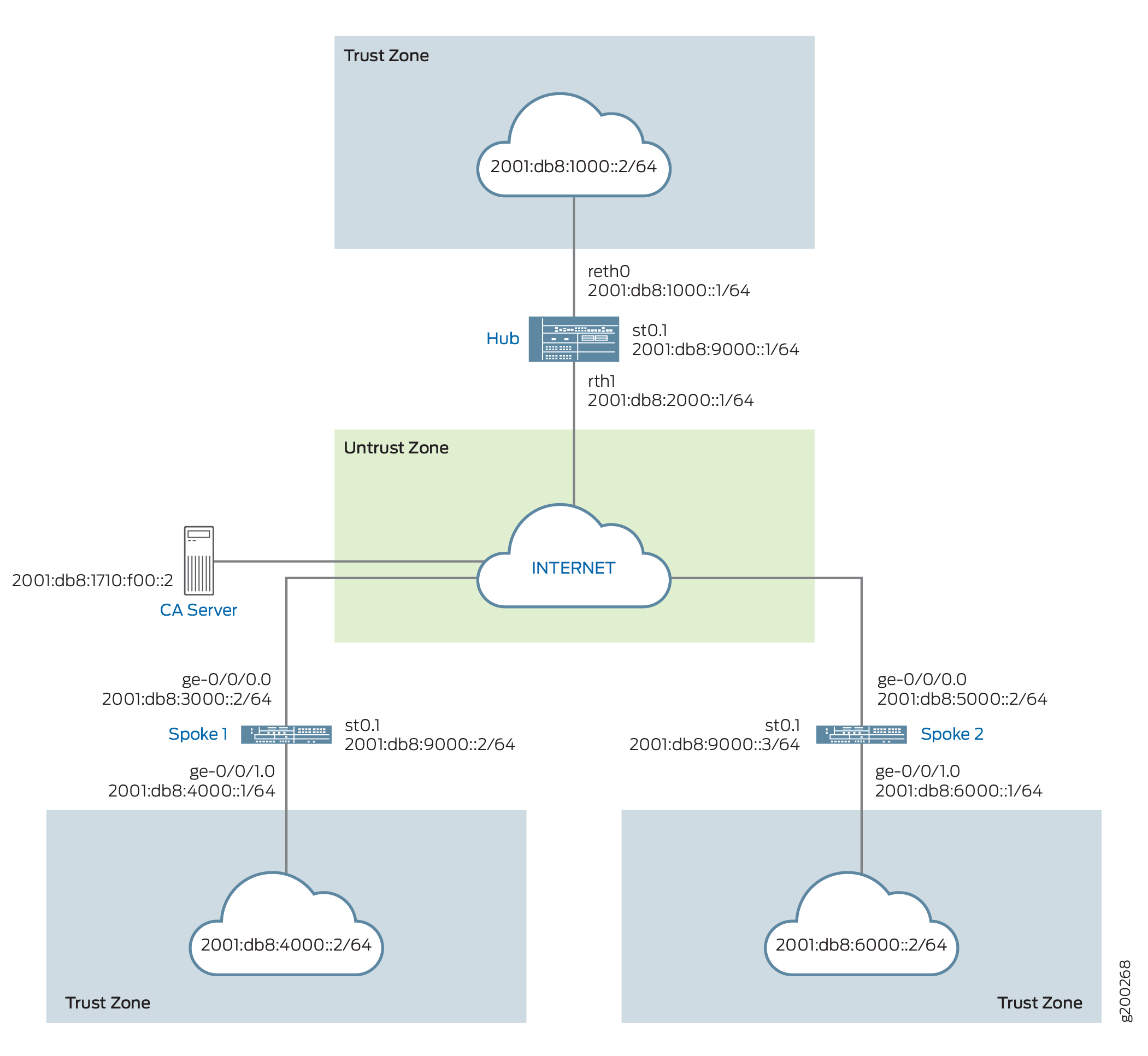
Configuration
To configure ADVPN, perform these tasks:
The first section describes how to obtain CA and local certificates online using the Simple Certificate Enrollment Protocol (SCEP) on the hub and spoke devices.
Enroll Device Certificates with SCEP
Step-by-Step Procedure
To enroll digital certificates with SCEP on the hub:
-
Configure the CA.
[edit]
user@host# set security pki ca-profile ca-profile1 ca-identity ca-profile1
user@host# set security pki ca-profile ca-profile1 enrollment url http://2001:db8:1710:f00::2/certsrv/mscep/mscep.dll
user@host# set security pki ca-profile ca-profile1 revocation-check disable
user@host# commit
-
Enroll the CA certificate.
user@host> request security pki ca-certificate enroll ca-profile ca-profile1
Type yes at the prompt to load the CA certificate.
-
Generate a key pair.
user@host> request security pki generate-key-pair certificate-id Local1
-
Enroll the local certificate.
user@host> request security pki local-certificate enroll ca-profile ca-profile1 certificate-id Local1 domain-name example.net email hub@example.net ip-address 10.1.1.1 subject DC=example.net,CN=hub,OU=SLT,O=example,L=Bengaluru,ST=KA,C=IN challenge-password <password>
-
Verify the local certificate.
user@host> show security pki local-certificate detail

Certificate identifier: Local1
  Certificate version: 3
  Serial number: 40a6d5f300000000258d
  Issuer:
    Common name: CASERVER1, Domain component: net, Domain component: internal
  Subject:
    Organization: example, Organizational unit: SLT, Country: IN, State: KA,
    Locality: Bengaluru, Common name: hub, Domain component: example.net
  Subject string:
    C=IN, DC=example.net, ST=KA, L=Bengaluru, O=example, OU=SLT, CN=hub
  Alternate subject: "hub@example.net", example.net, 10.1.1.1
  Validity:
    Not before: 11- 6-2012 09:39
    Not after: 11- 6-2013 09:49
  Public key algorithm: rsaEncryption(1024 bits)
    30:81:89:02:81:81:00:c9:c9:cc:30:b6:7a:86:12:89:b5:18:b3:76
    01:2d:cc:65:a8:a8:42:78:cd:d0:9a:a2:c0:aa:c4:bd:da:af:88:f3
    2a:78:1f:0a:58:e6:11:2c:81:8f:0e:7c:de:86:fc:48:4c:28:5b:8b
    34:91:ff:2e:91:e7:b5:bd:79:12:de:39:46:d9:fb:5c:91:41:d1:da
    90:f5:09:00:9b:90:07:9d:50:92:7d:ff:fb:3f:3c:bc:34:e7:e3:c8
    ea:cb:99:18:b4:b6:1d:a8:99:d3:36:b9:1b:36:ef:3e:a1:fd:48:82
    6a:da:22:07:da:e0:d2:55:ef:57:be:09:7a:0e:17:02:03:01:00:01
  Signature algorithm: sha1WithRSAEncryption
  Distribution CRL:
    http://ca-server1/CertEnroll/CASERVER1.crl
    file://\\ca-server1\CertEnroll\CASERVER1.crl
  Fingerprint:
    e1:f7:a1:a6:1e:c3:97:69:a5:07:9b:09:14:1a:c7:ae:09:f1:f6:35 (sha1)
    a0:02:fa:8d:5c:63:e5:6d:f7:f4:78:56:ac:4e:b2:c4 (md5)
  Auto-re-enrollment:
    Status: Disabled
    Next trigger time: Timer not started
Step-by-Step Procedure
To enroll digital certificates with SCEP on spoke 1:
-
Configure the CA.
[edit]
user@host# set security pki ca-profile ca-profile1 ca-identity ca-profile1
user@host# set security pki ca-profile ca-profile1 enrollment url http://2001:db8:1710:f00::2/certsrv/mscep/mscep.dll
user@host# set security pki ca-profile ca-profile1 revocation-check disable
user@host# commit
-
Enroll the CA certificate.
user@host> request security pki ca-certificate enroll ca-profile ca-profile1
Type yes at the prompt to load the CA certificate.
-
Generate a key pair.
user@host> request security pki generate-key-pair certificate-id Local1
-
Enroll the local certificate.
user@host> request security pki local-certificate enroll ca-profile ca-profile1 certificate-id Local1 domain-name example.net email spoke1@example.net ip-address 10.2.2.1 subject DC=example.net,CN=spoke1,OU=SLT,O=example,L=Mysore,ST=KA,C=IN challenge-password <password>
-
Verify the local certificate.
user@host> show security pki local-certificate detail

Certificate identifier: Local1
  Certificate version: 3
  Serial number: 40a7975f00000000258e
  Issuer:
    Common name: CASERVER1, Domain component: net, Domain component: internal
  Subject:
    Organization: example, Organizational unit: SLT, Country: IN, State: KA,
    Locality: Mysore, Common name: spoke1, Domain component: example.net
  Subject string:
    C=IN, DC=example.net, ST=KA, L=Mysore, O=example, OU=SLT, CN=spoke1
  Alternate subject: "spoke1@example.net", example.net, 10.2.2.1
  Validity:
    Not before: 11- 6-2012 09:40
    Not after: 11- 6-2013 09:50
  Public key algorithm: rsaEncryption(1024 bits)
    30:81:89:02:81:81:00:d8:45:09:77:cd:36:9a:6f:58:44:18:91:db
    b0:c7:8a:ee:c8:d7:a6:d2:e2:e7:20:46:2b:26:1a:92:e2:4e:8a:ce
    c9:25:d9:74:a2:81:ad:ea:e0:38:a0:2f:2d:ab:a6:58:ac:88:35:f4
    90:01:08:33:33:75:2c:44:26:f8:25:18:97:96:e4:28:de:3b:35:f2
    4a:f5:92:b7:57:ae:73:4f:8e:56:71:ab:81:54:1d:75:88:77:13:64
    1b:6b:01:96:15:0a:1c:54:e3:db:f8:ec:ec:27:5b:86:39:c1:09:a1
    e4:24:1a:19:0d:14:2c:4b:94:a4:04:91:3f:cb:ef:02:03:01:00:01
  Signature algorithm: sha1WithRSAEncryption
  Distribution CRL:
    http://ca-server1/CertEnroll/CASERVER1.crl
    file://\\ca-server1\CertEnroll\CASERVER1.crl
  Fingerprint:
    b6:24:2a:0e:96:5d:8c:4a:11:f3:5a:24:89:7c:df:ea:d5:c0:80:56 (sha1)
    31:58:7f:15:bb:d4:66:b8:76:1a:42:4a:8a:16:b3:a9 (md5)
  Auto-re-enrollment:
    Status: Disabled
    Next trigger time: Timer not started
The organizational unit (OU) shown in the subject field is
SLT. The IKE configuration on the hub includesou=SLTto identify the spoke.
Step-by-Step Procedure
To enroll digital certificates with SCEP on spoke 2:
-
Configure the CA.
[edit]
user@host# set security pki ca-profile ca-profile1 ca-identity ca-profile1
user@host# set security pki ca-profile ca-profile1 enrollment url http://2001:db8:1710:f00::2/certsrv/mscep/mscep.dll
user@host# set security pki ca-profile ca-profile1 revocation-check disable
user@host# commit
-
Enroll the CA certificate.
user@host> request security pki ca-certificate enroll ca-profile ca-profile1
Type yes at the prompt to load the CA certificate.
-
Generate a key pair.
user@host> request security pki generate-key-pair certificate-id Local1
-
Enroll the local certificate.
user@host> request security pki local-certificate enroll ca-profile ca-profile1 certificate-id Local1 domain-name example.net email spoke2@example.net ip-address 10.3.3.1 subject DC=example.net,CN=spoke2,OU=SLT,O=example,L=Tumkur,ST=KA,C=IN challenge-password <password>
-
Verify the local certificate.
user@host> show security pki local-certificate detail

Certificate identifier: Local1
  Certificate version: 3
  Serial number: 40bb71d400000000258f
  Issuer:
    Common name: CASERVER1, Domain component: net, Domain component: internal
  Subject:
    Organization: example, Organizational unit: SLT, Country: IN, State: KA,
    Locality: Tumkur, Common name: spoke2, Domain component: example.net
  Subject string:
    C=IN, DC=example.net, ST=KA, L=Tumkur, O=example, OU=SLT, CN=spoke2
  Alternate subject: "spoke2@example.net", example.net, 10.3.3.1
  Validity:
    Not before: 11- 6-2012 10:02
    Not after: 11- 6-2013 10:12
  Public key algorithm: rsaEncryption(1024 bits)
    30:81:89:02:81:81:00:b6:2e:e2:da:e6:ac:57:e4:5d:ff:de:f6:89
    27:d6:3e:1b:4a:3f:b2:2d:b3:d3:61:ed:ed:6a:07:d9:8a:d2:24:03
    77:1a:fe:84:e1:12:8a:2d:63:6e:bf:02:6b:15:96:5a:4f:37:a0:46
    44:09:96:c0:fd:bb:ab:79:2c:5d:92:bd:31:f0:3b:29:51:ce:89:8e
    7c:2b:02:d0:14:5b:0a:a9:02:93:21:ea:f9:fc:4a:e7:08:bc:b1:6d
    7c:f8:3e:53:58:8e:f1:86:13:fe:78:b5:df:0b:8e:53:00:4a:46:11
    58:4a:38:e9:82:43:d8:25:47:7d:ef:18:f0:ef:a7:02:03:01:00:01
  Signature algorithm: sha1WithRSAEncryption
  Distribution CRL:
    http://ca-server1/CertEnroll/CASERVER1.crl
    file://\\ca-server1\CertEnroll\CASERVER1.crl
  Fingerprint:
    1a:6d:77:ac:fd:94:68:ce:cf:8a:85:f0:39:fc:e0:6b:fd:fe:b8:66 (sha1)
    00:b1:32:5f:7b:24:9c:e5:02:e6:72:75:9e:a5:f4:77 (md5)
  Auto-re-enrollment:
    Status: Disabled
    Next trigger time: Timer not started
The organizational unit (OU) shown in the subject field is
SLT. The IKE configuration on the hub includesou=SLTto identify the spoke.
Configuring the Hub
CLI Quick Configuration
To quickly configure this example, copy the following commands, paste them
into a text file, remove any line breaks, change any details necessary to
match your network configuration, copy and paste the commands into the CLI
at the [edit] hierarchy level, and then enter
commit from configuration mode.
set chassis cluster reth-count 2
set chassis cluster node 0
set chassis cluster node 1
set chassis cluster redundancy-group 0 node 0 priority 254
set chassis cluster redundancy-group 0 node 1 priority 1
set chassis cluster redundancy-group 1 node 0 priority 254
set chassis cluster redundancy-group 1 node 1 priority 1
set security pki ca-profile ROOT-CA ca-identity ROOT-CA
set security pki ca-profile ROOT-CA enrollment url http://2001:db8:1710:f00::2/certsrv/mscep/mscep.dll
set security pki ca-profile ROOT-CA enrollment retry 5
set security pki ca-profile ROOT-CA enrollment retry-interval 0
set security pki ca-profile ROOT-CA revocation-check disable
set security ike proposal IKE_PROP authentication-method rsa-signatures
set security ike proposal IKE_PROP dh-group group19
set security ike proposal IKE_PROP authentication-algorithm sha-384
set security ike proposal IKE_PROP encryption-algorithm aes-256-cbc
set security ike proposal IKE_PROP lifetime-seconds 6000
set security ike policy IKE_POL mode main
set security ike policy IKE_POL proposals IKE_PROP
set security ike policy IKE_POL certificate local-certificate HUB
set security ike gateway IKE_GWA_1 ike-policy IKE_POL
set security ike gateway IKE_GWA_1 dynamic distinguished-name wildcard OU=SLT
set security ike gateway IKE_GWA_1 dynamic ike-user-type group-ike-id
set security ike gateway IKE_GWA_1 dead-peer-detection always-send
set security ike gateway IKE_GWA_1 dead-peer-detection interval 10
set security ike gateway IKE_GWA_1 dead-peer-detection threshold 3
set security ike gateway IKE_GWA_1 local-identity distinguished-name
set security ike gateway IKE_GWA_1 external-interface reth1
set security ike gateway IKE_GWA_1 advpn partner disable
set security ike gateway IKE_GWA_1 version v2-only
set security ipsec proposal IPSEC_PROP protocol esp
set security ipsec proposal IPSEC_PROP encryption-algorithm aes-256-gcm
set security ipsec proposal IPSEC_PROP lifetime-seconds 3000
set security ipsec policy IPSEC_POL perfect-forward-secrecy keys group19
set security ipsec policy IPSEC_POL proposals IPSEC_PROP
set security ipsec vpn IPSEC_VPNA_1 bind-interface st0.1
set security ipsec vpn IPSEC_VPNA_1 ike gateway IKE_GWA_1
set security ipsec vpn IPSEC_VPNA_1 ike ipsec-policy IPSEC_POL
set security policies default-policy permit-all
set security zones security-zone untrust host-inbound-traffic system-services all
set security zones security-zone untrust host-inbound-traffic protocols ospf3
set security zones security-zone untrust interfaces reth1.0
set security zones security-zone untrust interfaces st0.1
set security zones security-zone trust host-inbound-traffic system-services all
set security zones security-zone trust host-inbound-traffic protocols ospf3
set security zones security-zone trust interfaces reth0.0
set interfaces ge-0/0/0 gigether-options redundant-parent reth1
set interfaces ge-0/0/1 gigether-options redundant-parent reth0
set interfaces ge-7/0/0 gigether-options redundant-parent reth1
set interfaces ge-7/0/1 gigether-options redundant-parent reth0
set interfaces reth0 redundant-ether-options redundancy-group 1
set interfaces reth0 unit 0 family inet
set interfaces reth0 unit 0 family inet6 address 2001:db8:1000::1/64
set interfaces reth1 redundant-ether-options redundancy-group 1
set interfaces reth1 unit 0 family inet
set interfaces reth1 unit 0 family inet6 address 2001:db8:2000::1/64
set interfaces st0 unit 1 multipoint
set interfaces st0 unit 1 family inet6 address 2001:db8:9000::1/64
set routing-options rib inet6.0 static route 2001:db8:3000::0/64 next-hop 2001:db8:2000::2
set routing-options rib inet6.0 static route 2001:db8:5000::0/64 next-hop 2001:db8:2000::2
set protocols ospf3 area 0.0.0.0 interface reth0.0
set protocols ospf3 area 0.0.0.0 interface st0.1 interface-type p2mp
set protocols ospf3 area 0.0.0.0 interface st0.1 dynamic-neighbors
Step-by-Step Procedure
The following example requires you to navigate various levels in the configuration hierarchy.
To configure the hub:
-
Configure the interfaces.
[edit interfaces]
user@host# set ge-0/0/0 gigether-options redundant-parent reth1
user@host# set ge-0/0/1 gigether-options redundant-parent reth0
user@host# set ge-7/0/0 gigether-options redundant-parent reth1
user@host# set ge-7/0/1 gigether-options redundant-parent reth0
user@host# set reth0 redundant-ether-options redundancy-group 1
user@host# set reth0 unit 0 family inet
user@host# set reth0 unit 0 family inet6 address 2001:db8:1000::1/64
user@host# set reth1 redundant-ether-options redundancy-group 1
user@host# set reth1 unit 0 family inet
user@host# set reth1 unit 0 family inet6 address 2001:db8:2000::1/64
user@host# set st0 unit 1 multipoint
user@host# set st0 unit 1 family inet6 address 2001:db8:9000::1/64
-
Configure the routing protocol.
[edit protocols ospf3]
user@host# set ospf3 area 0.0.0.0 interface reth0.0
user@host# set ospf3 area 0.0.0.0 interface st0.1 interface-type p2mp
user@host# set ospf3 area 0.0.0.0 interface st0.1 dynamic-neighbors
[edit routing-options]
user@host# set rib inet6.0 static route 2001:db8:3000::0/64 next-hop 2001:db8:2000::2
user@host# set rib inet6.0 static route 2001:db8:5000::0/64 next-hop 2001:db8:2000::2
-
Configure Phase 1 options.
[edit security ike proposal IKE_PROP]
user@host# set authentication-method rsa-signatures
user@host# set dh-group group19
user@host# set authentication-algorithm sha-384
user@host# set encryption-algorithm aes-256-cbc
user@host# set lifetime-seconds 6000
[edit security ike policy IKE_POL]
user@host# set mode main
user@host# set proposals IKE_PROP
user@host# set certificate local-certificate HUB
[edit security ike gateway IKE_GWA_1]
user@host# set ike-policy IKE_POL
user@host# set dynamic distinguished-name wildcard OU=SLT
user@host# set ike-user-type group-ike-id
user@host# set dead-peer-detection always-send
user@host# set dead-peer-detection interval 10
user@host# set dead-peer-detection threshold 3
user@host# set local-identity distinguished-name
user@host# set external-interface reth1
user@host# set version v2-only
-
Configure Phase 2 options.
[edit security ipsec proposal IPSEC_PROP]
user@host# set protocol esp
user@host# set encryption-algorithm aes-256-gcm
user@host# set lifetime-seconds 3000
[edit security ipsec policy IPSEC_POL]
user@host# set perfect-forward-secrecy keys group19
user@host# set proposals IPSEC_PROP
[edit security ipsec vpn IPSEC_VPNA_1]
user@host# set bind-interface st0.1
user@host# set ike gateway IKE_GWA_1
user@host# set ike ipsec-policy IPSEC_POL
-
Configure zones.
[edit security zones security-zone untrust]
user@host# set host-inbound-traffic system-services all
user@host# set host-inbound-traffic protocols ospf3
user@host# set interfaces reth1.0
user@host# set interfaces st0.1
[edit security zones security-zone trust]
user@host# set host-inbound-traffic system-services all
user@host# set host-inbound-traffic protocols ospf3
user@host# set interfaces reth0.0
-
Configure the default security policy.
[edit security policies]
user@host# set default-policy permit-all
-
Configure the CA profile.
[edit security pki]
user@host# set ca-profile ROOT-CA ca-identity ROOT-CA
user@host# set ca-profile ROOT-CA enrollment url http://2001:db8:1710:f00::2/certsrv/mscep/mscep.dll
user@host# set ca-profile ROOT-CA enrollment retry 5
user@host# set ca-profile ROOT-CA enrollment retry-interval 0
user@host# set pki ca-profile ROOT-CA revocation-check disable
-
Configure chassis cluster
[edit chassis cluster]
set reth-count 2
set node 0
set node 1
set redundancy-group 0 node 0 priority 254
set redundancy-group 0 node 1 priority 1
set redundancy-group 1 node 0 priority 254
set redundancy-group 1 node 1 priority 1
Results
From configuration mode, confirm your configuration by entering the
show interfaces, show protocols,
show routing-options, show security
ike, show security ipsec, show
security zones, show security policies, and
show security pki
show chassis cluster commands. If the output does not
display the intended configuration, repeat the configuration instructions in
this example to correct it.
[edit]
user@host# show interfaces
ge-0/0/0 {
    gigether-options {
        redundant-parent reth1;
    }
}
ge-0/0/1 {
    gigether-options {
        redundant-parent reth0;
        }
    }
    reth0 {
        redundant-ether-options {
            redundancy-group 1;
        }
        unit 0 {
            family inet;
            family inet6 {
                address 2001:db8:1000::1/64;
            }
        }
    }
    reth1 {
        redundant-ether-options {
            redundancy-group 1;
        }
        unit 0 {
            family inet;
            family inet6 {
                address 2001:db8:2000::1/64;
            }
        }
    }
    st0 {
        unit 1 {
            multipoint;
            family inet6 {
                address 2001:db8:9000::1/64 {
                    primary;
                }
            }
        }
    }
[edit]
user@host# show protocols
ospf3 {
    area 0.0.0.0 {
        interface st0.1 {
            interface-type p2mp;
            demand-circuit;
            dynamic-neighbors;
        }
        interface ge-0/0/1.0;
        interface reth0.0;
    }
}
[edit]
user@host# show routing-options
rib inet6.0 {
    static {
        route 2001:db8:3000::/64 next-hop 2001:db8:2000::2;
        route 2001:db8:5000::/64 next-hop 2001:db8:2000::2;
    }
}
[edit]
user@host# show security ike
proposal IKE_PROP {
    authentication-method rsa-signatures;
    dh-group group19;
    authentication-algorithm sha-384;
    encryption-algorithm aes-256-cbc;
    lifetime-seconds 6000;
}
policy IKE_POL {
    mode main;
    proposals IKE_PROP;
    certificate {
        local-certificate HUB;
    }
}
gateway IKE_GWA_1 {
    ike-policy IKE_POL;
    dynamic {
        distinguished-name {
            wildcard OU=SLT;
        }
        ike-user-type group-ike-id;
    }
    dead-peer-detection {
        always-send;
        interval 10;
        threshold 3;
    }
    local-identity distinguished-name;
    external-interface reth1;
    advpn {
        partner {
            disable;
        }
    }
    version v2-only;
}
[edit]
user@host# show security ipsec
proposal IPSEC_PROP {
    protocol esp;
    encryption-algorithm aes-256-gcm;
    lifetime-seconds 3000;
}
policy IPSEC_POL {
    perfect-forward-secrecy {
        keys group19;
    }
    proposals IPSEC_PROP;
}
vpn IPSEC_VPNA_1 {
    bind-interface st0.1;
    ike {
        gateway IKE_GWA_1;
        ipsec-policy IPSEC_POL;
    }
}
[edit]
user@host# show security zones
security-zone untrust {
    host-inbound-traffic {
        system-services {
            all;
        }
        protocols {
            ospf3;
        }
    }
    interfaces {
        st0.1;
        reth1.0;
    }
}
security-zone trust {
    host-inbound-traffic {
        system-services {
            all;
        }
        protocols {
            ospf3;
        }
    }
    interfaces {
        reth0.0;
    }
}
[edit]
user@host# show security policies
default-policy {
    permit-all;
}
[edit]
user@host# show security pki
ca-profile ROOT-CA {
    ca-identity ROOT-CA;
    enrollment {
        url http://2001:db8:1710:f00::2/certsrv/mscep/mscep.dll;
        retry 5;
        retry-interval 0;
    }
    revocation-check {
        disable;
    }
}
If you are done configuring the device, enter commit from
configuration mode.
Configuring Spoke 1
CLI Quick Configuration
To quickly configure this example, copy the following commands, paste them
into a text file, remove any line breaks, change any details necessary to
match your network configuration, copy and paste the commands into the CLI
at the [edit] hierarchy level, and then enter
commit from configuration mode.
set security pki ca-profile ROOT-CA ca-identity ROOT-CA
set security pki ca-profile ROOT-CA enrollment url http://2001:db8:1710:f00::2/certsrv/mscep/mscep.dll
set security pki ca-profile ROOT-CA enrollment retry 5
set security pki ca-profile ROOT-CA enrollment retry-interval 0
set security pki ca-profile ROOT-CA revocation-check disable
set security ike proposal IKE_PROP authentication-method rsa-signatures
set security ike proposal IKE_PROP dh-group group19
set security ike proposal IKE_PROP authentication-algorithm sha-384
set security ike proposal IKE_PROP encryption-algorithm aes-256-cbc
set security ike proposal IKE_PROP lifetime-seconds 6000
set security ike policy IKE_POL mode main
set security ike policy IKE_POL proposals IKE_PROP
set security ike policy IKE_POL certificate local-certificate SPOKE1
set security ike gateway IKE_GW_SPOKE_1 ike-policy IKE_POL
set security ike gateway IKE_GW_SPOKE_1 address 2001:db8:2000::1
set security ike gateway IKE_GW_SPOKE_1 dead-peer-detection always-send
set security ike gateway IKE_GW_SPOKE_1 dead-peer-detection interval 10
set security ike gateway IKE_GW_SPOKE_1 dead-peer-detection threshold 3
set security ike gateway IKE_GW_SPOKE_1 local-identity distinguished-name
set security ike gateway IKE_GW_SPOKE_1 remote-identity distinguished-name container OU=SLT
set security ike gateway IKE_GW_SPOKE_1 external-interface ge-0/0/0.0
set security ike gateway IKE_GW_SPOKE_1 advpn suggester disable
set security ike gateway IKE_GW_SPOKE_1 version v2-only
set security ipsec proposal IPSEC_PROP protocol esp
set security ipsec proposal IPSEC_PROP encryption-algorithm aes-256-gcm
set security ipsec proposal IPSEC_PROP lifetime-seconds 3000
set security ipsec policy IPSEC_POL perfect-forward-secrecy keys group19
set security ipsec policy IPSEC_POL proposals IPSEC_PROP
set security ipsec vpn IPSEC_VPN_SPOKE_1 bind-interface st0.1
set security ipsec vpn IPSEC_VPN_SPOKE_1 ike gateway IKE_GW_SPOKE_1
set security ipsec vpn IPSEC_VPN_SPOKE_1 ike ipsec-policy IPSEC_POL
set security ipsec vpn IPSEC_VPN_SPOKE_1 establish-tunnels immediately
set security policies default-policy permit-all
set security zones security-zone trust host-inbound-traffic system-services all
set security zones security-zone trust host-inbound-traffic protocols ospf3
set security zones security-zone trust interfaces ge-0/0/1.0
set security zones security-zone untrust host-inbound-traffic system-services all
set security zones security-zone untrust host-inbound-traffic protocols ospf3
set security zones security-zone untrust interfaces st0.1
set security zones security-zone untrust interfaces ge-0/0/0.0
set interfaces ge-0/0/0 unit 0 family inet6 address 2001:db8:3000::2/64
set interfaces ge-0/0/1 unit 0 family inet6 address 2001:db8:4000::1/64
set interfaces st0 unit 1 multipoint
set interfaces st0 unit 1 family inet6 address 2001:db8:9000::2/64
set routing-options rib inet6.0 static route 2001:db8:2000::0/64 next-hop 2001:db8:3000::1
set protocols ospf3 area 0.0.0.0 interface ge-0/0/1.0
set protocols ospf3 area 0.0.0.0 interface st0.1 interface-type p2mp
set protocols ospf3 area 0.0.0.0 interface st0.1 dynamic-neighbors
Step-by-Step Procedure
The following example requires you to navigate various levels in the configuration hierarchy.
To configure spoke 1:
-
Configure interfaces.
[edit interfaces]
user@host# set ge-0/0/0 unit 0 family inet6 address 2001:db8:3000::2/64
user@host# set ge-0/0/1 unit 0 family inet6 address 2001:db8:4000::1/64
user@host# set st0 unit 1 multipoint
user@host# set st0 unit 1 family inet6 address 2001:db8:9000::2/64
-
Configure the routing protocol.
[edit protocols ospf3]
set area 0.0.0.0 interface ge-0/0/1.0
set area 0.0.0.0 interface st0.1 interface-type p2mp
set area 0.0.0.0 interface st0.1 dynamic-neighbors
[edit routing-options]
user@host# set rib inet6.0 static route 2001:db8:2000::/64 next-hop 2001:db8:3000::1
-
Configure Phase 1 options.
[edit security ike proposal IKE_PROP]
user@host# set authentication-method rsa-signatures
user@host# set dh-group group19
user@host# set authentication-algorithm sha-384
user@host# set encryption-algorithm aes-256-cbc
user@host# set lifetime-seconds 6000
[edit security ike policy IKE_POL]
user@host# set mode main
user@host# set proposals IKE_PROP
user@host# set certificate local-certificate SPOKE1
[edit security ike gateway IKE_GW_SPOKE_1]
user@host# set ike-policy IKE_POL
user@host# set address 2001:db8:2000::1
user@host# set dead-peer-detection always-send
user@host# set dead-peer-detection interval 10
user@host# set dead-peer-detection threshold 3
user@host# set local-identity distinguished-name
user@host# set remote-identity distinguished-name container OU=SLT
user@host# set external-interface ge-0/0/0.0
user@host# set advpn suggester disable
user@host# set version v2-only
-
Configure Phase 2 options.
[edit security ipsec proposal IPSEC_PROPl]
user@host# set protocol esp
user@host# set encryption-algorithm aes-256-gcm
user@host# set lifetime-seconds 3000
[edit security ipsec policy IPSEC_POL]
user@host# set perfect-forward-secrecy keys group19
user@host# set proposals IPSEC_PROP
[edit security ipsec vpn IPSEC_VPN_SPOKE_1]
user@host# set bind-interface st0.1
user@host# set ike gateway IKE_GW_SPOKE_1
user@host# set ike ipsec-policy IPSEC_POL
user@host# set establish-tunnels immediately
-
Configure zones.
[edit security zones security-zone untrust]
user@host# set host-inbound-traffic system-services all
user@host# set host-inbound-traffic protocols ospf3
user@host# set interfaces st0.1
user@host# set interfaces ge-0/0/0.0
[edit security zones security-zone trust]
user@host# set host-inbound-traffic system-services all
user@host# set host-inbound-traffic protocols ospf3
user@host# set interfaces ge-0/0/1.0
-
Configure the default security policy.
[edit security policies]
user@host# set default-policy permit-all
-
Configure the CA profile.
[edit security pki]
user@host# set ca-profile ROOT-CA ca-identity ROOT-CA
user@host# set ca-profile ROOT-CA enrollment url http://2001:db8:1710:f00::2/certsrv/mscep/mscep.dll
user@host# set ca-profile ROOT-CA enrollment retry 5
user@host# set ca-profile ROOT-CA enrollment retry-interval 0
user@host# set ca-profile ROOT-CA revocation-check disable
Results
From configuration mode, confirm your configuration by entering the
show interfaces, show protocols,
show routing-options, show security
ike, show security ipsec, show
security zones, show security policies, and
show security pki commands. If the output does not
display the intended configuration, repeat the configuration instructions in
this example to correct it.
[edit]
user@host# show interfaces
ge-0/0/0 {
    unit 0 {
        family inet6 {
            address 2001:db8:3000::2/64;
        }
    }
}
ge-0/0/1 {
    unit 0 {
        family inet6 {
            address 2001:db8:4000::1/64;
        }
    }
}
st0 {
    unit 1 {
        multipoint;
        family inet6 {
            address 2001:db8:9000::2/64;
        }
    }
}
[edit]
user@host# show protocols
ospf3 {
    area 0.0.0.0 {
        interface st0.1 {
            interface-type p2mp;
            dynamic-neighbors;
        }
        interface ge-0/0/1.0;
    }
}
[edit]
user@host# show routing-options
rib inet6.0 {
    static {
        route 2001:db8:2000::/64 next-hop [ 2001:db8:3000::1 2001:db8:5000::1 ];
    }
}
[edit]
user@host# show security ike
proposal IKE_PROP {
    authentication-method rsa-signatures;
    dh-group group19;
    authentication-algorithm sha-384;
    encryption-algorithm aes-256-cbc;
    lifetime-seconds 6000;
}
policy IKE_POL {
    mode main;
    proposals IKE_PROP;
    certificate {
        local-certificate SPOKE1;
    }
}
gateway IKE_GW_SPOKE_1 {
    ike-policy IKE_POL;
    address 2001:db8:2000::1;
    dead-peer-detection {
        always-send;
        interval 10;
        threshold 3;
    }
    local-identity distinguished-name;
    remote-identity distinguished-name container OU=SLT;
    external-interface ge-0/0/0.0;
    advpn {
        suggester {
            disable;
        }
    }
    version v2-only;
}
[edit]
user@host# show security ipsec
proposal IPSEC_PROP {
    protocol esp;
    encryption-algorithm aes-256-gcm;
    lifetime-seconds 3000;
}
policy IPSEC_POL {
    perfect-forward-secrecy {
        keys group19;
    }
    proposals IPSEC_PROP;
}
vpn IPSEC_VPN_SPOKE_1 {
    bind-interface st0.1;
    ike {
        gateway IKE_GW_SPOKE_1;
        ipsec-policy IPSEC_POL;
    }
    establish-tunnels immediately;
}
[edit]
user@host# show security zones
security-zone untrust {
    host-inbound-traffic {
        system-services {
            all;
        }
        protocols {
            ospf3;
        }
    }
    interfaces {
        st0.1;
        ge-0/0/0.0;
    }
}
security-zone trust {
    host-inbound-traffic {
        system-services {
            all;
        }
        protocols {
            ospf3;
        }
    }
    interfaces {
         ge-0/0/1.0;
    }
}
[edit]
user@host# show security policies
default-policy {
    permit-all;
}
[edit]
user@host# show security pki
ca-profile ROOT-CA {
    ca-identity ROOT-CA;
    enrollment {
        url http://2001:db8:1710:f00::2/certsrv/mscep/mscep.dll;
        retry 5;
        retry-interval 0;
    }
    revocation-check {
        disable;
    }
}
If you are done configuring the device, enter commit from
configuration mode.
Configuring Spoke 2
CLI Quick Configuration
To quickly configure this example, copy the following commands, paste them
into a text file, remove any line breaks, change any details necessary to
match your network configuration, copy and paste the commands into the CLI
at the [edit] hierarchy level, and then enter
commit from configuration mode.
set security pki ca-profile ROOT-CA ca-identity ROOT-CA
set security pki ca-profile ROOT-CA enrollment url http://2001:db8:1710:f00::2/certsrv/mscep/mscep.dll
set security pki ca-profile ROOT-CA enrollment retry 5
set security pki ca-profile ROOT-CA enrollment retry-interval 0
set security pki ca-profile ROOT-CA revocation-check disable
set security ike proposal IKE_PROP authentication-method rsa-signatures
set security ike proposal IKE_PROP dh-group group19
set security ike proposal IKE_PROP authentication-algorithm sha-384
set security ike proposal IKE_PROP encryption-algorithm aes-256-cbc
set security ike proposal IKE_PROP lifetime-seconds 6000
set security ike policy IKE_POL mode main
set security ike policy IKE_POL proposals IKE_PROP
set security ike policy IKE_POL certificate local-certificate SPOKE2
set security ike gateway IKE_GW_SPOKE_2 ike-policy IKE_POL
set security ike gateway IKE_GW_SPOKE_2 address 2001:db8:2000::1
set security ike gateway IKE_GW_SPOKE_2 dead-peer-detection always-send
set security ike gateway IKE_GW_SPOKE_2 dead-peer-detection interval 10
set security ike gateway IKE_GW_SPOKE_2 dead-peer-detection threshold 3
set security ike gateway IKE_GW_SPOKE_2 local-identity distinguished-name
set security ike gateway IKE_GW_SPOKE_2 remote-identity distinguished-name container OU=SLT
set security ike gateway IKE_GW_SPOKE_2 external-interface ge-0/0/0.0
set security ike gateway IKE_GW_SPOKE_2 advpn suggester disable
set security ike gateway IKE_GW_SPOKE_2 version v2-only
set security ipsec proposal IPSEC_PROP protocol esp
set security ipsec proposal IPSEC_PROP encryption-algorithm aes-256-gcm
set security ipsec proposal IPSEC_PROP lifetime-seconds 3000
set security ipsec policy IPSEC_POL perfect-forward-secrecy keys group19
set security ipsec policy IPSEC_POL proposals IPSEC_PROP
set security ipsec vpn IPSEC_VPN_SPOKE_2 bind-interface st0.1
set security ipsec vpn IPSEC_VPN_SPOKE_2 ike gateway IKE_GW_SPOKE_2
set security ipsec vpn IPSEC_VPN_SPOKE_2 ike ipsec-policy IPSEC_POL
set security ipsec vpn IPSEC_VPN_SPOKE_2 establish-tunnels immediately
set security policies default-policy permit-all
set security zones security-zone trust host-inbound-traffic system-services all
set security zones security-zone trust host-inbound-traffic protocols ospf3
set security zones security-zone trust interfaces ge-0/0/1.0
set security zones security-zone untrust host-inbound-traffic system-services all
set security zones security-zone untrust host-inbound-traffic protocols ospf3
set security zones security-zone untrust interfaces st0.1
set security zones security-zone untrust interfaces ge-0/0/0.0
set interfaces ge-0/0/0 unit 0 family inet6 address 2001:db8:5000::2/64
set interfaces ge-0/0/1 unit 0 family inet6 address 2001:db8:6000::1/64
set interfaces st0 unit 1 family inet6 address 2001:db8:9000::3/64
set routing-options rib inet6.0 static route 2001:db8:2000::/64 next-hop 2001:db8:5000::1
set protocols ospf3 area 0.0.0.0 interface ge-0/0/1.0
set protocols ospf3 area 0.0.0.0 interface st0.1 interface-type p2mp
set protocols ospf3 area 0.0.0.0 interface st0.1 dynamic-neighbors
Step-by-Step Procedure
The following example requires you to navigate various levels in the configuration hierarchy.
To configure spoke 2:
-
Configure interfaces.
[edit interfaces]
user@host# set ge-0/0/0 unit 0 family inet6 address 2001:db8:5000::2/64
user@host# set ge-0/0/1 unit 0 family inet6 address 2001:db8:6000::1/64
user@host# set st0 unit 1 family inet6 address 2001:db8:9000::3/64
-
Configure the routing protocol.
[edit protocols ospf3]
user@host# set area 0.0.0.0 interface st0.1 interface-type p2mp
user@host# set area 0.0.0.0 interface st0.1 dynamic-neighbors
user@host# set area 0.0.0.0 interface ge-0/0/1.0
[edit routing-options]
user@host# set rib inet6.0 static route 2001:db8:2000::/64 next-hop 2001:db8:5000::1
-
Configure Phase 1 options.
[edit security ike proposal IKE_PROP]
user@host# set authentication-method rsa-signatures
user@host# set dh-group group19
user@host# set authentication-algorithm sha-384
user@host# set encryption-algorithm aes-256-cbc
user@host# set lifetime-seconds 6000
[edit security ike policy IKE_POL]
user@host# set mode main
user@host# set proposals IKE_PROP
user@host# set certificate local-certificate SPOKE2
[edit security ike gateway IKE_GW_SPOKE_2]
user@host# set ike-policy IKE_POL
user@host# set address 2001:db8:2000::1
user@host# set dead-peer-detection always-send
user@host# set dead-peer-detection interval 10
user@host# set dead-peer-detection threshold 3
user@host# set local-identity distinguished-name
user@host# set remote-identity distinguished-name container OU=SLT
user@host# set external-interface ge-0/0/0.0
user@host# set advpn suggester disable
user@host# set version v2-only
-
Configure Phase 2 options.
[edit security ipsec proposal IPSEC_PROPl]
user@host# set protocol esp
user@host# set encryption-algorithm aes-256-gcm
user@host# set lifetime-seconds 3000
[edit security ipsec policy IPSEC_POL]
user@host# set perfect-forward-secrecy keys group19
user@host# set proposals IPSEC_PROP
[edit security ipsec vpn IPSEC_VPN_SPOKE_2]
user@host# set bind-interface st0.1
user@host# set ike gateway IKE_GW_SPOKE_2
user@host# set ike ipsec-policy IPSEC_POL
user@host# set establish-tunnels immediately
-
Configure zones.
[edit security zones security-zone untrust]
user@host# set host-inbound-traffic system-services all
user@host# set host-inbound-traffic protocols ospf3
user@host# set interfaces st0.1
user@host# set interfaces ge-0/0/0.0
[edit security zones security-zone trust]
user@host# set host-inbound-traffic system-services all
user@host# set host-inbound-traffic protocols ospf3
user@host# set interfaces ge-0/0/1.0
-
Configure the default security policy.
[edit security policies]
user@host# set default-policy permit-all
-
Configure the CA profile.
[edit security pki]
user@host# set ca-profile ROOT-CA ca-identity ROOT-CA
user@host# set ca-profile ROOT-CA enrollment url http://2001:db8:1710:f00::2/certsrv/mscep/mscep.dll
user@host# set ca-profile ROOT-CA enrollment retry 5
user@host# set ca-profile ROOT-CA enrollment retry-interval 0
user@host# set ca-profile ROOT-CA revocation-check disable
Results
From configuration mode, confirm your configuration by entering the
show interfaces, show protocols,
show routing-options, show security
ike, show security ipsec, show
security zones, show security policies, and
show security pki commands. If the output does not
display the intended configuration, repeat the configuration instructions in
this example to correct it.
[edit]
user@host# show interfaces
ge-0/0/0 {
    unit 0 {
        family inet6 {
            address 2001:db8:5000::2/64;
        }
    }
}
ge-0/0/1 {
    unit 0 {
        family inet6 {
            address 2001:db8:6000::1/64;
        }
    }
}
    st0 {
        unit 1 {
            family inet6 {
                address 2001:db8:9000::3/64;
            }
        }
    }
[edit]
user@host# show protocols
ospf3 {
    area 0.0.0.0 {
        interface st0.1 {
            interface-type p2mp;
            dynamic-neighbors;
        }
        interface ge-0/0/1.0;
    }
}
[edit]
user@host# show routing-options
rib inet6.0 {
    static {
    route 2001:db8:2000::/64 next-hop [ 2001:db8:3000::1 2001:db8:5000::1 ];
    }
}
[edit]
user@host# show security ike
proposal IKE_PROP {
    authentication-method rsa-signatures;
    dh-group group19;
    authentication-algorithm sha-384;
    encryption-algorithm aes-256-cbc;
    lifetime-seconds 6000;
}
policy IKE_POL {
    mode main;
    proposals IKE_PROP;
    certificate {
        local-certificate SPOKE2;
    }
}
gateway IKE_GW_SPOKE_2 {
    ike-policy IKE_POL;
    address 2001:db8:2000::1;
    dead-peer-detection {
        always-send;
        interval 10;
        threshold 3;
    }
    local-identity distinguished-name;
    remote-identity distinguished-name container OU=SLT;
    external-interface ge-0/0/0.0;
    advpn {
        suggester {
        disable
        }
    }
    version v2-only;
}
[edit]
user@host# show security ipsec
proposal IPSEC_PROP {
    protocol esp;
    encryption-algorithm aes-256-gcm;
    lifetime-seconds 3000;
}
policy IPSEC_POL {
    perfect-forward-secrecy {
        keys group19;
    }
    proposals IPSEC_PROP;
}
vpn IPSEC_VPN_SPOKE_2 {
    bind-interface st0.1;
    ike {
        gateway IKE_GW_SPOKE_2;
        ipsec-policy IPSEC_POL;
    }
    establish-tunnels immediately;
}
[edit]
user@host# show security zones
security-zone untrust {
    host-inbound-traffic {
        system-services {
            all;
        }
        protocols {
            ospf3;
        }
    }
    interfaces {
        ge-0/0/0.0;
        st0.1;
    }
}
    security-zone trust {
        host-inbound-traffic {
            system-services {
                all;
            }
            protocols {
                ospf3;
            }
        }
        interfaces {
            ge-0/0/1.0;
        }
    }
[edit]
user@host# show security policies
default-policy {
    permit-all;
}
[edit]
user@host# show security pki
ca-profile ROOT-CA {
    ca-identity ROOT-CA;
    enrollment {
        url http://2001:db8:1710:f00::2/certsrv/mscep/mscep.dll;
        retry 5;
        retry-interval 0;
    }
    revocation-check {
        disable;
    }
}
If you are done configuring the device, enter commit from
configuration mode.
Verification
Confirm that the configuration is working properly.
Verifying IKE Status
Purpose
Verify the IKE status.
Action
From operational mode, enter the show security ike sa command.
user@host> show security ike sa
Index   State Initiator cookie          Responder cookie          Mode Remote Address

4295070 UP    2001:db8:1ad4ba7a115fa229 2001:db8:32e6382a058bb296 Main 2001:db8:3000::2

295069  UP    2001:db8:88a1520c20cbbe04 2001:db8:7fa4c8e365393c48 Main 2001:db8:5000::2
Meaning
The show security ike sa command lists all active IKE Phase
1 SAs. If no SAs are listed, there was a problem with Phase 1 establishment.
Check the IKE policy parameters and external interface settings in your
configuration. Phase 1 proposal parameters must match on the hub and
spokes.
Verifying IPsec Status
Purpose
Verify the IPsec status.
Action
From operational mode, enter the show security ipsec sa command.
user@host> show security ipsec sa
Total active tunnels: 2     Total Ipsec sas: 2
  ID    Algorithm       SPI      Life:sec/kb  Mon lsys Port  Gateway
  <67108881 ESP:aes-gcm-256/None 3dba3f80 2979/ unlim - root 500 2001:db8:5000::2
  >67108881 ESP:aes-gcm-256/None 46746d5d 2979/ unlim - root 500 2001:db8:5000::2
  <67108882 ESP:aes-gcm-256/None 16dceb60 2992/ unlim - root 500 2001:db8:3000::2
  >67108882 ESP:aes-gcm-256/None 681209c2 2992/ unlim - root 500 2001:db8:3000::2
Meaning
The show security ipsec sa command lists all active IKE
Phase 2 SAs. If no SAs are listed, there was a problem with Phase 2
establishment. Check the IKE policy parameters and external interface
settings in your configuration. Phase 2 proposal parameters must match on
the hub and spokes.
Verifying IPsec Next-Hop Tunnels
Purpose
Verify the IPsec next-hop tunnels.
Action
From operational mode, enter the show security ipsec next-hop-tunnels command.
user@host> show security ipsec next-hop-tunnels
Next-hop gateway              interface  IPSec VPN name Flag IKE-ID                            XAUTH username
2001:db8:9000::2              st0.1      IPSEC_VPNA_1   Auto C=US, DC=example.net, ST=CA, L=Sunnyvale, O=example, OU=SLT, CN=SPOKE1 Not-Available
2001:db8:9000::3              st0.1      IPSEC_VPNA_1   Auto C=US, DC=example.net, ST=CA, L=Sunnyvale, O=example, OU=SLT, CN=SPOKE2 Not-Available
2001:db8::5668:ad10:fcd8:10c8 st0.1      IPSEC_VPNA_1   Auto C=US, DC=example.net, ST=CA, L=Sunnyvale, O=example, OU=SLT, CN=SPOKE2 Not-Available
2001:db8::5668:ad10:fcd8:112f st0.1      IPSEC_VPNA_1   Auto C=US, DC=example.net, ST=CA, L=Sunnyvale, O=example, OU=SLT, CN=SPOKE1 Not-Available
Meaning
The next-hop gateways are the IP addresses for the st0
interfaces of the spokes. The next hop should be associated with the correct
IPsec VPN name.
Verifying OSPFv3
Purpose
Verify that OSPFv3 references the IP addresses for the st0
interfaces of the spokes.
Action
From operational mode, enter the show ospf3 neighbor interface command.
user@host> show ospf3 neighbor interface
ID                        Interface              State   Pri   Dead
2001:db8:9000:2   st0.1                  Full    128      -
  Neighbor-address 2001:db8::5668:ad10:fcd8:110e


2001:db8:20:54:49.693       	INFO 	${ret} = ID      Interface  State Pri Dead
2001:db8:9000:3   st0.1                  Full    128      -
  Neighbor-address 2001:db8::5668:ad10:fcd8:110e
Enabling OSPF to Update Routes Quickly After ADVPN Shortcut Tunnels Are Established
Problem
Description
OSPF can take up to 9 seconds to update a shortcut route in the routing table. It can take up to 10 seconds before traffic is forwarded to the shortcut tunnel.
Symptoms
When a shortcut tunnel is established between two shortcut partners, OSPF initiates an OSPF hello packet. Because of the timing of the shortcut tunnel establishment and the OSPF neighbor installation, the first packet in the tunnel might be dropped. This can cause OSPF to try again to establish an OSPF adjacency.
By default, the interval at which the OSPF retries to establish an adjacency is 10 seconds. After a shortcut tunnel is established, it can take more than 10 seconds for OSPF to establish an adjacency between the partners.
Solution
Configuring a smaller retry interval, such as 1 or 2 seconds, can enable OSPF to establish adjacencies faster over the shortcut tunnel. For example, use the following configurations:
[edit]
set protocols ospf area 0.0.0.0 interface st0.1 retransmit-interval 1
set protocols ospf area 0.0.0.0 interface st0.1 dead-interval 40
Platform-Specific Multicast in ADVPN Behavior
Use Feature Explorer to confirm platform and release support for specific features.
Use the following table to review platform-specific behaviors for your platform.
|
Platform |
Difference |
|---|---|
|
SRX Series |
|
Change History Table
Feature support is determined by the platform and release you are using. Use Feature Explorer to determine if a feature is supported on your platform.
p2mp interface type is introduced for
PIM
for IPsec VPN with kmd
process.