IPsec VPN Support in Multinode High Availability
IPsec VPN in Active-Backup Mode
SRX Series Firewalls support IPsec VPN tunnels in a Multinode High Availability setup. Prior to Junos OS Release 22.4R1, IPsec VPN tunnel anchors at SRG1, where SRG1 acts in stateful active / backup mode. In this mode, all VPN tunnels terminate on the same device where the SRG1 is active.
Multinode High Availability establishes IPsec tunnel and performs key exchanges by:
-
Dynamically associating the floating IP address of the active SRG1 for the termination IP in routing deployment and assigns the termination IP, the virtual IP(VIP), which floats between the two devices in switching mode.
-
Generating the CA profile, when there is a need for a dynamic CA profile to authenticate the tunnel establishment, on the node where SRG1 is active.
-
Performing new authentication and loading the dynamic profile on the newly active node and clearing on the old node.
Although you can run the show commands on both active and backup nodes to
display the status of IKE and IPsec security associations, you can delete the IKE and IPsec
security associations only on the active node.
VPN service is automatically enabled when you enable the active/backup mode using the
set chassis high-availability services-redundancy-group 1 command. See
the configuration example for more details.
PKI files are synchronized to the peer node only if you enable link encryption for the ICL.
We recommend following sequence when you configure VPN with Multinode High Availability on your security device:
-
On the backup node, configure security IKE gateway, IPsec VPN, interfaces st0.x, and security zones and then commit the configuration.
-
On the active node, configure security IKE gateway, IPsec VPN, st0.x interface, security zones, and static route and commit the configuration.
You must commit the configuration on the backup node before committing configuration on the active node if you don't use the commit synchronize option.
Process Packets on Backup Node
When you use the process-packet-on-backup option in Multinode High
Availability, the Packet Forward Engine forwards packets on backup node for the
corresponding SRG. This configuration processes VPN packets on the backup node even when
the node is not in active mode; thus, eliminating the delay when backup node transitions
to the active role after a failover. The packet process continues even during the
transition period.
You can configure the process packet on backup on an SRG1 using the [set chassis
high-availability services-redundancy-group name process-packet-on-backup]
statement.
IPsec VPN in Active-Active Mode
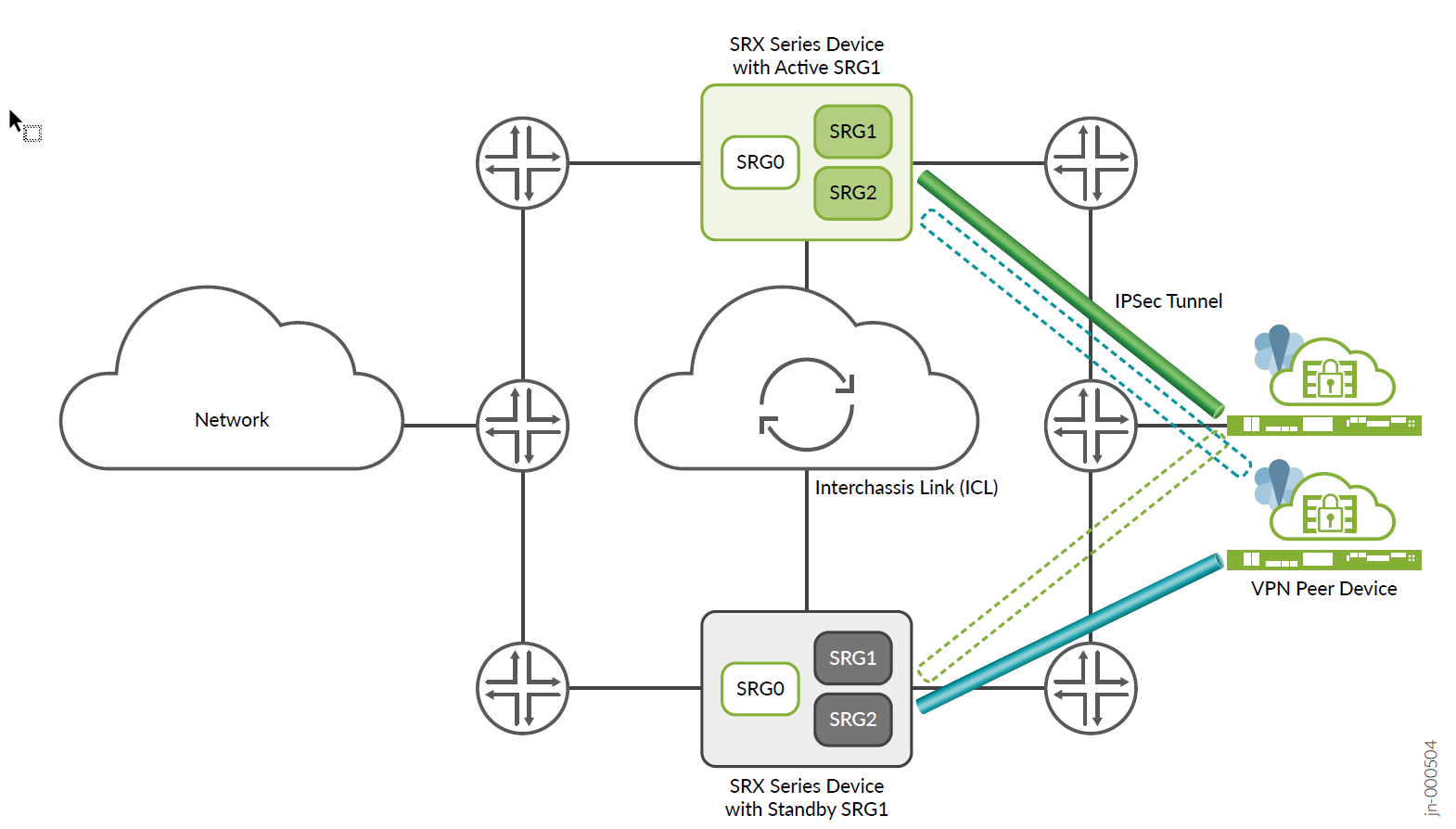
Starting in Junos OS Release 22.4R1, you can configure Multinode High Availability to operate in active-active mode with support of multi SRG1s (SRG1+) for IPsec VPN. In this mode, some SRGs remain active on one node and some SRGs remain active on another node. A particular SRG always operates in active-backup mode; it operates in active mode on one node and backup mode on another node.
Multinode High Availability supports IPsec VPN in active-active mode with multiple SRGs (SRG1+). In this mode, you can establish multiple active tunnels from both the nodes, based on SRG activeness. Since different SRGs can be active on different nodes, tunnels belonging to these SRGs come up on both nodes independently. Having active tunnels on both the nodes enables encrypting/decrypting data traffic on both the nodes resulting in efficient use of bandwidth.
Figure 1 and Figure 2 show differences in active-backup and active-active Multinode High Availabilty IPsec VPN tunnels.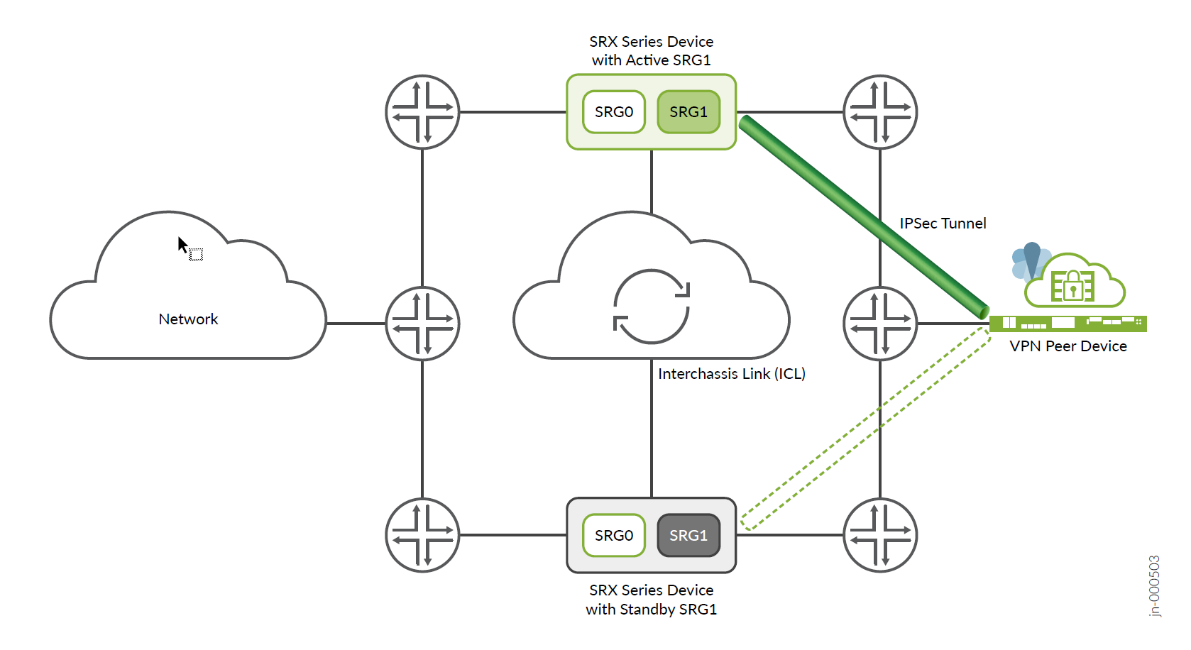
Multinode High Availability establishes IPsec tunnel and performs key exchanges by associating termination IP address (which also identifies the tunnels ending on it) to the SRG. Since different SRG1+ can be in active state or in backup state on each of the devices, Multinode High Availability steers the matching traffic effectively to the corresponding active SRG1. Multinode High Availability also maintains the SRG ID and IP prefix mapping information.
Table 1 and Table 2 provide details on impact on IPsec VPN tunnels due to change in SRG1+ changes.
| SRG1 Changes | Impact on IPSec VPN Tunnels |
|---|---|
| SRG addition | No impact on existing tunnels |
| SRG deletion |
Deletes all routes associated with the SRG. |
| SRG attribute (other than prefix-list) modification | No impact on existing tunnels |
| SRG ID modification | Deletes all existing tunnels associated with the SRG. |
| IP-prefix in prefix-list modification |
Deletes all tunnels mapping to that particular IP prefix. No impact if there is no existing tunnel mapping to the modified IP prefix. |
| SRG State Changes | Action from Multinode High Availability |
|---|---|
|
|
Deletes all data corresponding to that SRG, and resynchronizes from new the active SRG |
|
|
Deletes all data corresponding to that SRG, and resynchronizes from new the active SRG |
|
|
Not applicable |
|
|
No action |
|
|
No action |
|
|
No action |
|
|
No action (possible state transition; if Active state is not involved in either pre or post state, no action is required) |
|
|
No action (possible state transition; if Active state is not involved in either pre or post state, no action is required) |
|
|
No action (possible state transition; if Active state is not involved in either pre or post state, no action is required) |
Associate IPsec VPN Service to an SRG
Releases before 22.4R1 supported only SRG0 and SRG1, and SRG1 was associated to IPsec VPN by default. In 22.4R1, an SRG is not associated to the IPSec VPN service by default. You must associate the IPsec VPN service to any of the multiple SRGs by:
- Specifying IPsec as managed service
Ex:
[set chassis high-availability services-redundancy-group <id> managed-services ipsec] - Creating an IP prefix list
Ex:
[set chassis high-availability
                services-redundancy-group <id> prefix-list <name>]
[set policy-options prefix-list <name> <IP address>
When you have multiple SRGs in your Multinode High Availability setup, some SRGs are in active state on one node and some SRGs are active on another node. You can anchor certain IPsec tunnels to particular node (SRX Series firewall) by configuring an IP prefix list.
In IPsec VPN configuration, an IKE gateway initiates and terminates network connections between two security devices. The local end (local IKE gateway) is the SRX Series interface that initiates IKE negotiations. Local IKE gateway has a local IP address, a publicly routable IP address on the firewall, which the VPN connection uses as the endpoint.
IP prefix list includes a list of IPv4 or IPv6 address prefixes, which are used as local address of an IKE gateway. You can associate these IP prefixes (prefix-list) with a specified SRG1 to advertise local address of IKE gateway with a higher preference according to state of the SRG.
To anchor a certain IPsec VPN tunnel to a particular security device, then you must:
-
Create an IP prefix list by including the local address of IKE gateway and associate the IP prefix list to the SRG:
Example:
set chassis high-availability services-redundancy-group 1 prefix-list lo0_1
set chassis high-availability services-redundancy-group 2 prefix-list lo0_2
set policy-options prefix-list lo0_1 10.11.0.1/32
set policy-options prefix-list lo0_2 10.11.1.1/32
set interfaces lo0 description untrust
set interfaces lo0 unit 0 family inet address 10.11.0.1/32
set interfaces lo0 unit 0 family inet address 10.11.1.1/32
- Define the routing-instance for the prefix list.
set chassis high-availability services-redundancy-group 1 prefix-list lo0_1 routing-instance rt-vr
set chassis high-availability services-redundancy-group 1 prefix-list lo0_2 routing-instance rt-vr
If you do not associate a routing-instance for the prefix-list, Multinode High Availability uses the default routing table, that might affect VPN functionality.
-
Associate/enable IPsec VPN to the SRG.
Example:
set chassis high-availability services-redundancy-group 1 managed-services ipsec
set chassis high-availability services-redundancy-group 2 managed-services ipsec
This configuration allows you to selectively and flexibly associate IPsec VPN to one of the multiple SRGs configured on SRX Series Firewall in a Multinode High Availability setup.
You can check the mapping of IKE/IPsec objects to the SRG by using the following command:
user@host# show chassis high-availability information detail
.........
Services Redundancy Group: 1
        Deployment Type: SWITCHING
        Status: BACKUP
        Activeness Priority: 200
        Hold Timer: 1
        Services: [ IPSEC ]
        Process Packet In Backup State: NO
        Control Plane State: NOT READY
        System Integrity Check: COMPLETE
        Peer Information:
        Failure Events: NONE
          Peer Id: 2
          Last Advertised HA Status: ACTIVE
          Last Advertised Health Status: HEALTHY
          Failover Readiness: N/A

.............
You can check the mapping of SRGs and IP prefix list by using the following command:
user@host> show chassis high-availability prefix-srgid-table
IP SRGID Table:
        SRGID    IP Prefix                                   Routing Table
        1        10.11.0.1/32                                rt-vr

        1        10.19.0.1/32                                rt-vr

        1        10.20.0.1/32                                rt-vr

        2        10.11.1.1/32                                rt-vr

        2        10.19.1.1/32                                rt-vr

        2        10.20.1.1/32                                rt-vr
If you do not configure a prefix list, you'll get the following warning message:
user@host> show chassis high-availability prefix-srgid-table
    Warning: prefix list not configured
See Example: Configure IPSec VPN in Active-Active Multinode High Availability in a Layer 3 Network for details.
Dynamic Routing Protocol Support for IPsec VPN
Starting in Junos OS Release 23.2R1, you can enable dynamic routing protocols for IPsec VPN in a Multinode High Availability setup by using node-local tunnels. The routes that the dynamic routing protocols add remain local to a node. These routes are not bound to any services redundancy group (SRG).
In the previous releases, Multinode High Availability supports only traffic selector deployment. That is, when you configure IPsec VPN by using traffic selectors, the configuration installs routes by considering the preference value and the routing metric based on traffic selector prefixes.
When you configure node-local tunnels, you have separate tunnels from a VPN peer device to both the nodes of the Multinode High Availability setup. That is—you have one node-local tunnel to each of the two Multinode High Availability nodes.
Figure 3, Figure 4, and Figure 5 show a Multinode High Availability IPsec VPN deployment with synced tunnels, node-local tunnels, and a combination of synced tunnels and node-local tunnels, respectively.
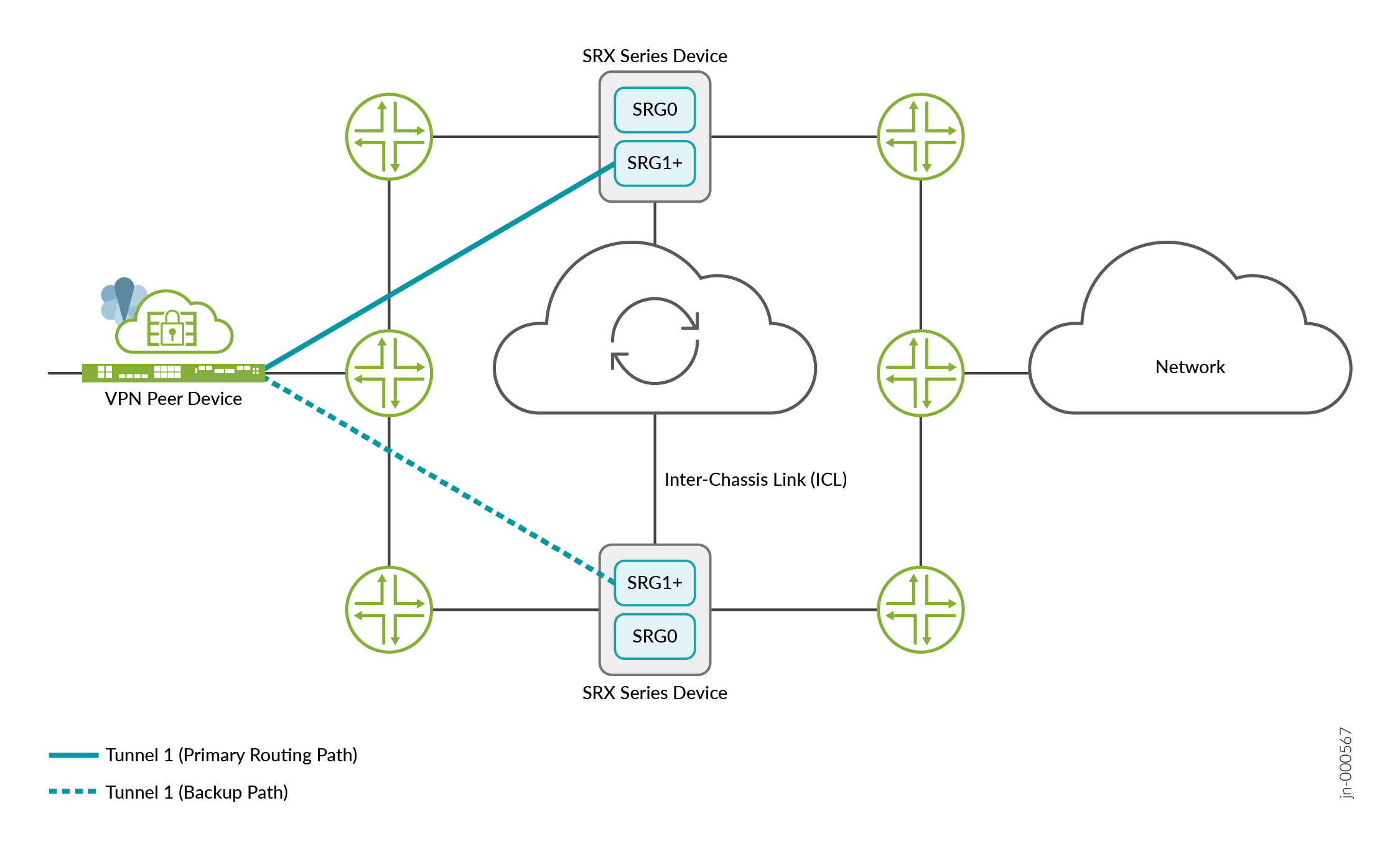
The preceding figure shows an IPsec VPN tunnel between a peer device and a Multinode High Availability setup. The IPsec VPN tunnel anchors at an active SRG1+. The tunnel remains active when the associated SRG1+ is active. In this deployment, traffic runs through the active tunnel (Tunnel 1).
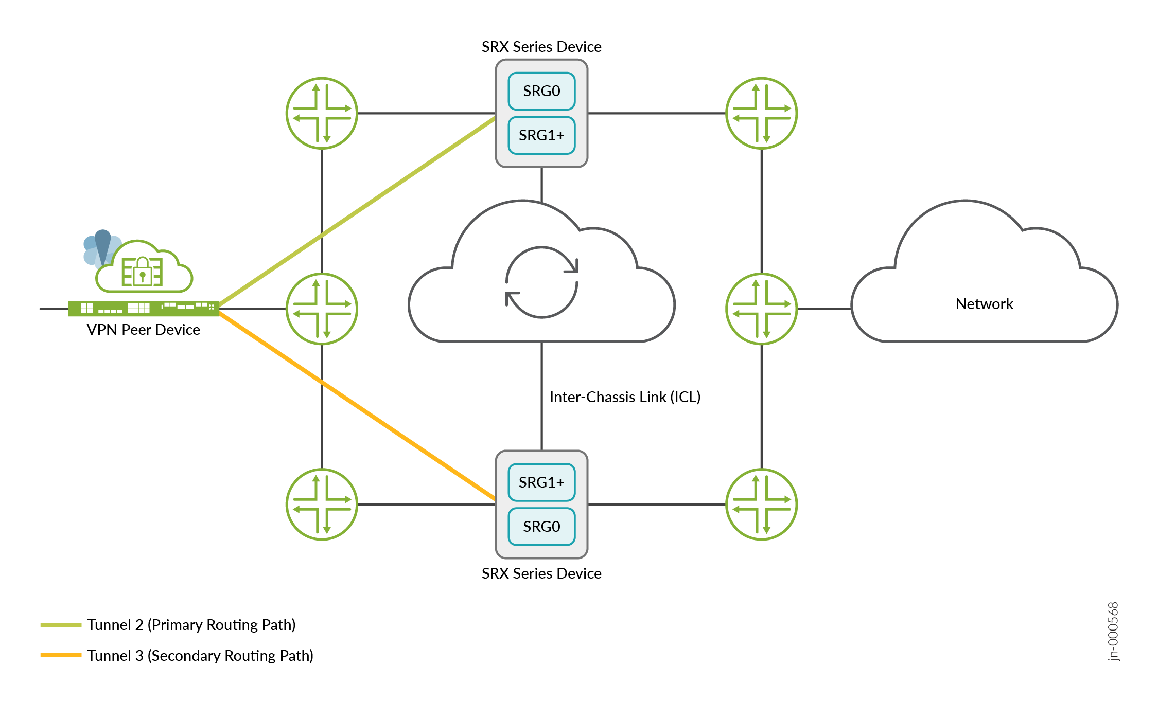
In the preceding figure, you have two node-local tunnels between the VPN peer device and the Multinode High Availability setup. Each tunnel connects to one of the two nodes in the setup. These tunnels are not associated with any SRG1+. Either one or both the tunnels can remain active at any instant. Based on the configured routing protocol, at any instant, traffic runs either through Tunnel 2 or through Tunnel 3.
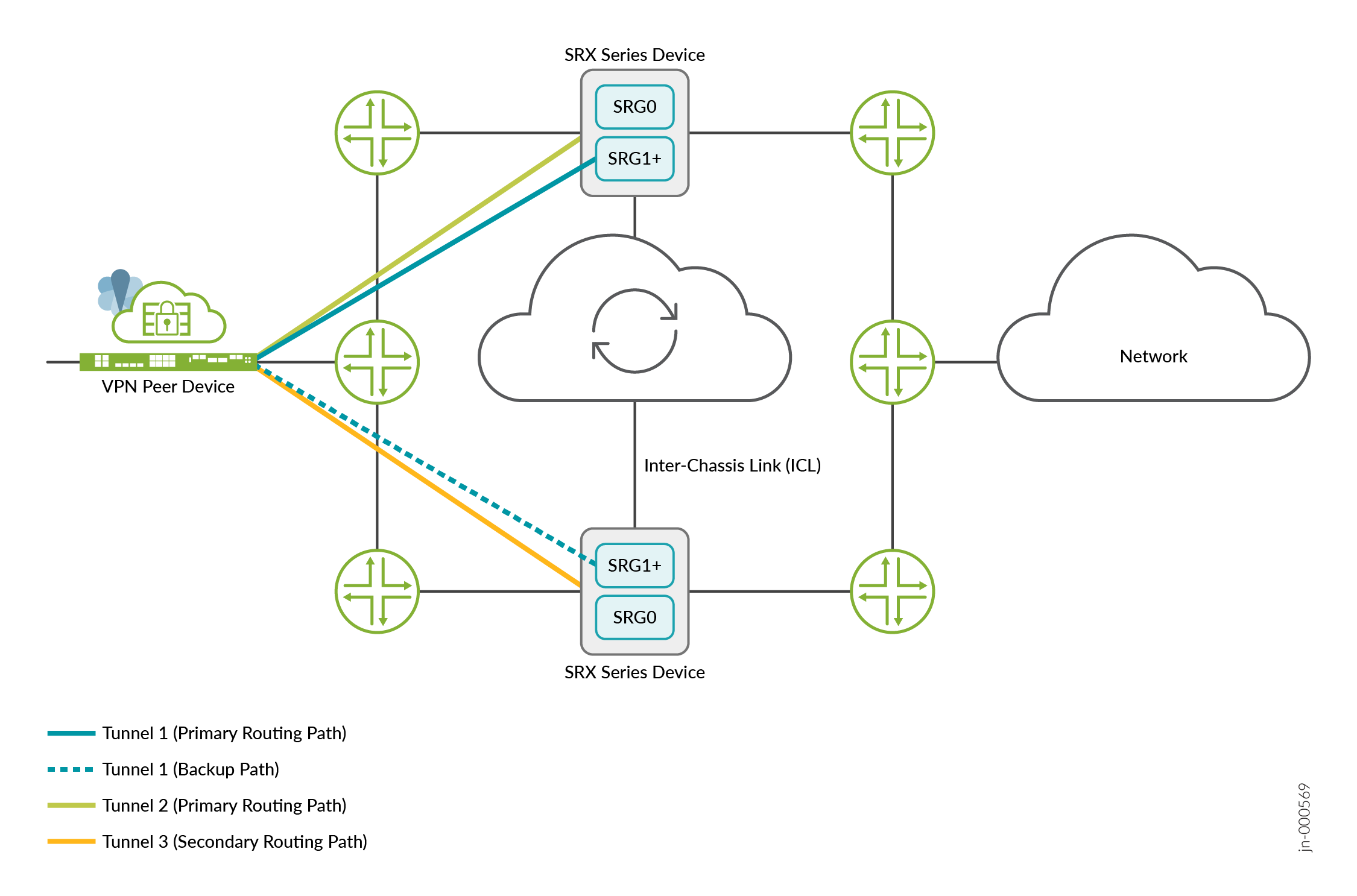
The preceding figure shows an IPsec VPN tunnel between a VPN peer device and a Multinode High Availability setup. Additionally, the figure shows two node-local tunnels between the VPN peer device and the Multinode High Availability setup.
The IPsec VPN tunnel anchors at an active SRG1+ and remains active when the associated SRG1+ is active. In the case of node-local tunnels, both the tunnels remain active.
Table 3 shows
the difference between node-local tunnels and synced tunnels.
| Functions | Node-Local Tunnels | Synced Tunnels |
|---|---|---|
| Association with SRG1+ | No | Yes |
| Tunnel information synchronization between Multinode High Availability nodes | No | Yes |
| Number of active tunnels | Two | One |
Mark an IPsec VPN Tunnel as Node-Local Tunnel
You can configure an IPsec VPN tunnel as node-local on an SRX Series
Firewall by using the following statement:
[edit]
user@host# set security ike gateway gateway-name node-local
Ensure that you configure the node-local option for both the nodes in a
Multinode High Availability setup.
Ensure that you set a preference for one tunnel when you configure the routing policy.
ADVPN Support in Multinode High Availability
Starting in Junos OS Release 24.2R1, Multinode High Availability support ADVPN in node-local tunnel deployment.
Node-local tunnels enhance Multinode HA by providing separate tunnels from a VPN peer device to both nodes in the setup. ADVPN allows VPN tunnels to be established dynamically between spokes. Combining ADVPN with Multinode HA in node-local tunnels deployment ensures robust network connectivity, efficient resource utilization, and seamless failover.
The ADVPN protocol allows creation of shortcut path between two partners gateways to establish an optimal path for data delivery. Traditionally, in a hub-and-spoke network, traffic between two spokes traverses through the hub. With ADVPN, the hub recommends a shortcut between its peers (spoke devices) with which it has previously established an IPsec SA. The decision to suggest a shortcut depends on the duration and amount of traffic flowing between a pair of peers through the hub. These peers, called as the shortcut partners, accept or decline this recommendation, according to their own policies.
The peers accept the suggestion and establish a direct SA (shortcut) between them. A new phase1 and phase2 SA is created for each shortcut. This shortcut is then used to establish a more optimal path for data delivery. All traffic flowing between the peers now goes directly over the shortcut tunnel between the peers.
If the peers decline the recommendation, they respond back to the suggester indicating the reason for rejection. In this case the traffic continues to flow through the Shortcut Suggester.
The Multinode High Availability setup includes two SRX Series Firewalls acting as active node and backup node and two VPN peer devices with node-local configuration. In this case, an IPsec VPN tunnel is establishes between a VPN peer device and a Multinode High Availability setup.
- Shortcut suggester: Notices traffic moving between peers and suggests shortcuts.
- Shortcut partners: These are peer devices that form the shortcut tunnel. The shortcut exchange happens through an extended IKEv2 protocol.
In Multinode High Availability setup, a VPN peer device, with node-local tunnel, takes up the following roles:
- ADVPN shortcut partner
- ADVPN shortcut suggester
With ADVPN configuration, an SRX Series Firewall can act as either a shortcut suggester or a shortcut partner, but not as both suggester and partner at a time.
The following images illustrate how VPN gateway can act as a shortcut suggester and partner.
- VPN peer device, acting as shortcut partner, establishes two tunnels– one tunnel towards
each Multinode High Availability node. In this case, each node acts as an shortcut
suggester. Figure 6: VPN Gateway as Shortcut Partner
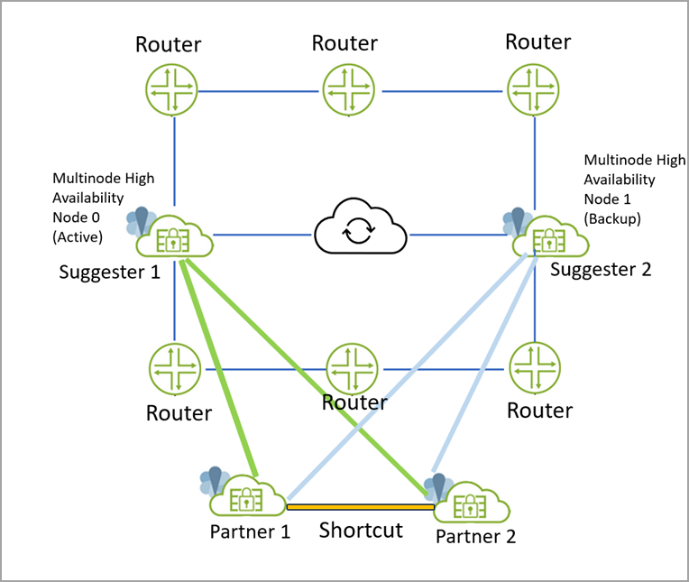
As shown in the illustration:
- Two SRX Series Firewalls in Multinode High Availability are acting as shortcut suggester— Suggester-1 (active node) and Suggester-2 (backup node).
- Two VPN Gateways are acting as shortcut partners—Partner-1 and Partner-2.
- The Partner-1 creates two tunnels; one towards Suggester-1 and another towards Sugester-2
- The Partner-2 creates two tunnels; one towards Suggester-1 and another towards Sugester-2
- Traffic from Partner-1 to Partner-2 goes through Suggester-1. Suggester-1 notifies Partner-1 and Partner-2 to create shortcut.
- In case if active node (suggester-1) fails and both tunnels from Suggester-1 to both Partner-1 and Partner-2 are down, in that case:
-
- The shortcut created earlier remains active, however, the traffic flow from Partner-1 to Partner-2 passes through Suggester-2. In this case, Suggester-2 suggests shortcut between Partner-1 and Partner-2. Since the shortcut already exists between Partner-1 and Partner-2, the suggestion for the new shortcut Suggester-2 gets rejected.
- VPN peer device acting as shortcut suggester. In this case, each Multinode High
Availability node acts as shortcut partner and establishes a separate tunnel towards VPN
peer device.Figure 7: VPN Gateway as Shortcut Suggester
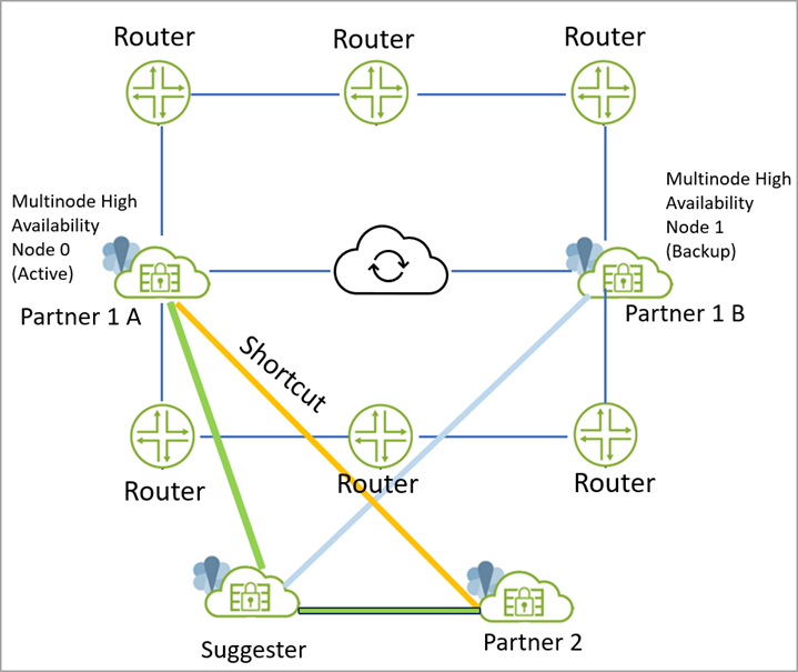
- SRX Series Firewalls in Multinode High Availability are acting as Partner-1-A and Partner-1-B.
- One VPN gateway is acting as Suggester and another SRX Series Firewall is acting as Partner-2.
- Partner-1-A (active node) creates static tunnel (active tunnel) with Suggester.
- Partner-1-B (backup node) creates static tunnel (backup tunnel) with Suggester.
- Traffic from Partner-1-A to Partner-2 flows through Suggester.
- Suggester suggests creating shortcut between Partner-1-A and Partner-2.
- Partner-1-A and Partner-2 create a shortcut between them. Note that if the static tunnel between partners and suggester goes down, there is no impact on Shortcut tunnel. Traffic continues to flow through the Shortcut tunnel even after static tunnel goes down.
Configuration Highlights
- Configure Multinode High Availability on SRX Series Firewalls. See Example: Configure Multinode High Availability in a Layer 3 Network.
- Ensure that you configure the
node-localoption for both the nodes in a Multinode High Availability setup. Example:set security ike gateway gateway-name node-local
- Configure shortcut partner or shortcut suggester roles on SRX Series Firewall as applicable. See Auto Discovery VPNs.
By default both shortcut suggester and shortcut partner options are enabled if you configure advpn under IKE gateway hierarchy. You must explicitly disable suggester option or partner option to disable that particular functionality.
[edit security ike]
gateway gateway_1 {
    …
    node-local
    …
    advpn {
        partner disable;
    }
}
[edit security ike]
gateway gateway_1 {
    advpn {
        suggester disable;

        partner {
            connection-limit 5;
            idle-time 300;
        }
    }
}
Limitations
- Configuring an ADVPN suggester is only allowed on AutoVPN hubs where as partner functionality for spoke configuration.
- You cannot configure both suggester and partner roles under the same IKE gateway
- ADVPN does not support IKEv1
- You cannot create a shortcut between partners that are both behind NAT devices.