Two-Node Multinode High Availability
Learn about the two-node Multinode High Availability solution.
Two-node Multinode High Availability supports two Junos firewalls presenting themselves as independent nodes to the rest of the network. The nodes are connected to adjacent infrastructure belonging to the same or different networks, all depending on the deployment mode. These nodes can either be collocated or separated across geographies. Participating nodes back up each other to ensure a fast synchronized failover in case of system or hardware failure.
Junos OS Firewalls support Multinode High Availability in active/backup mode and in active-active mode (with support of multiple services redundancy groups (SRGs). For the complete list of supported features and platforms, see Multinode High Availability in Feature Explorer.
Deployment Scenarios
Following types of network deployment models are supported for Multinode High Availability:
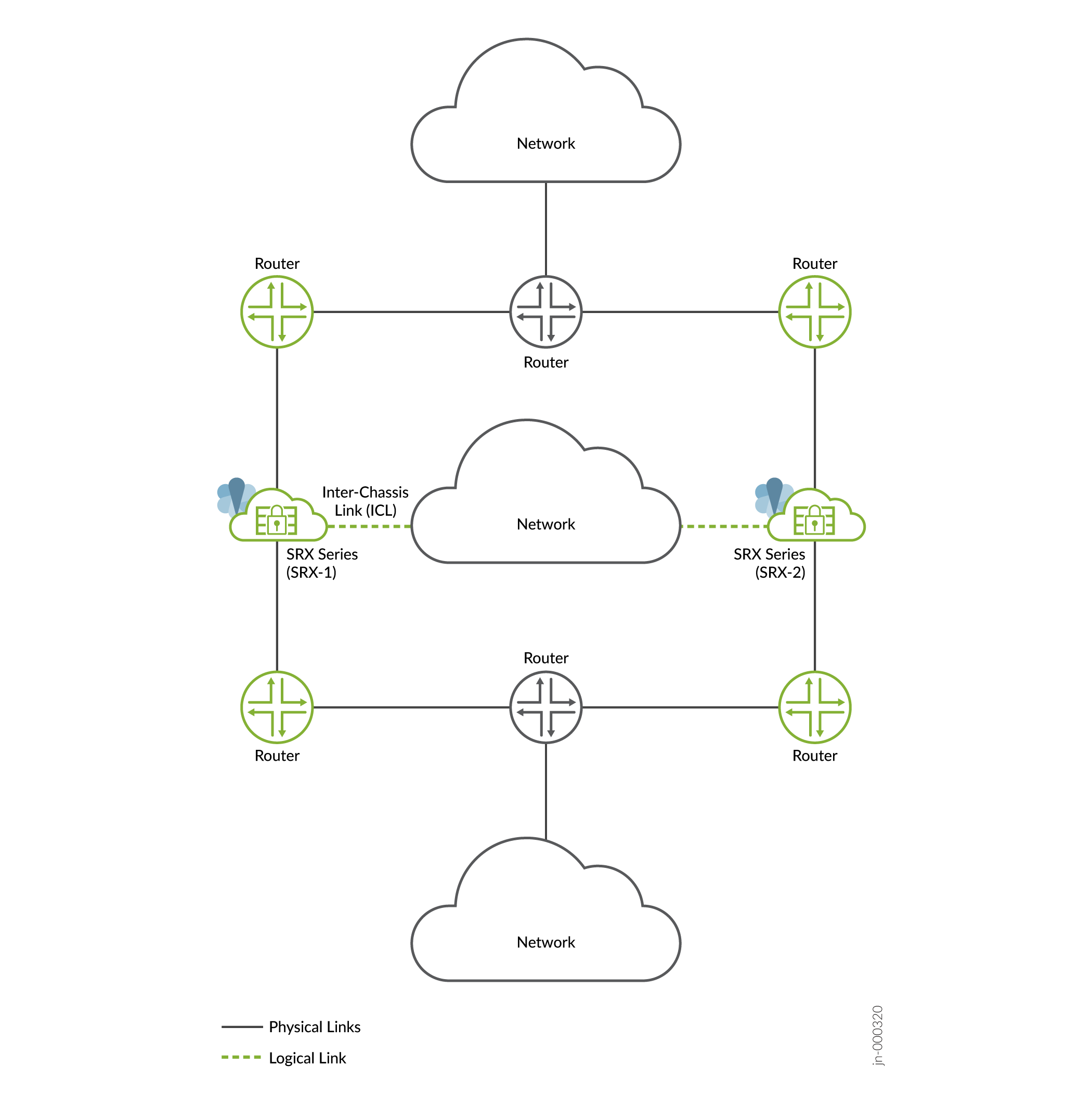
- Route mode (all interfaces connected using a Layer 3 topology) Figure 1: Layer 3 Mode
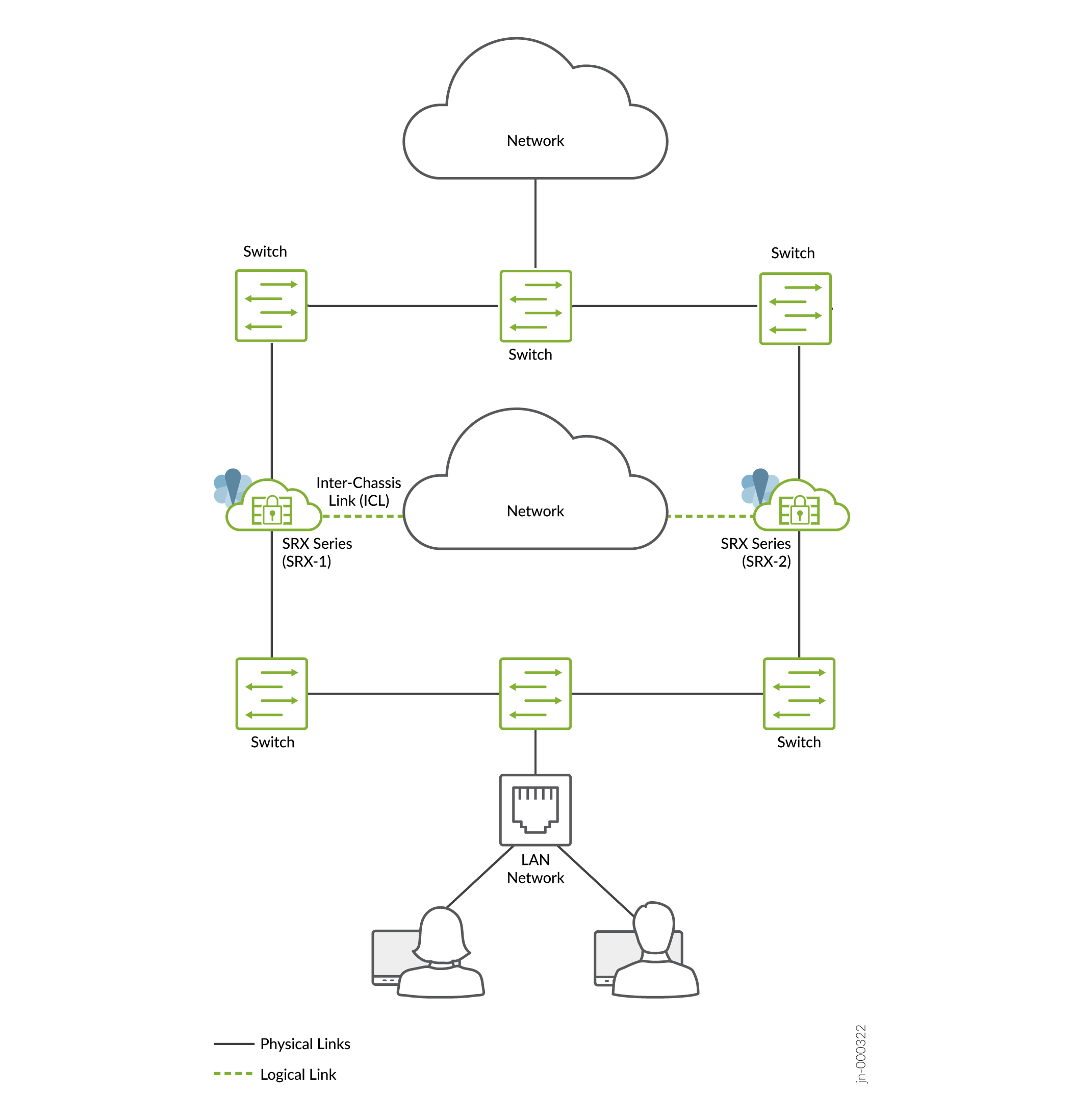
- Default gateway mode (all interfaces connected using an Layer 2 topology) used in more traditional environments. Common deployment of DMZ networks where the firewall devices act as the default gateway for the hosts and applications on the same segment.Figure 2: Default Gateway Mode
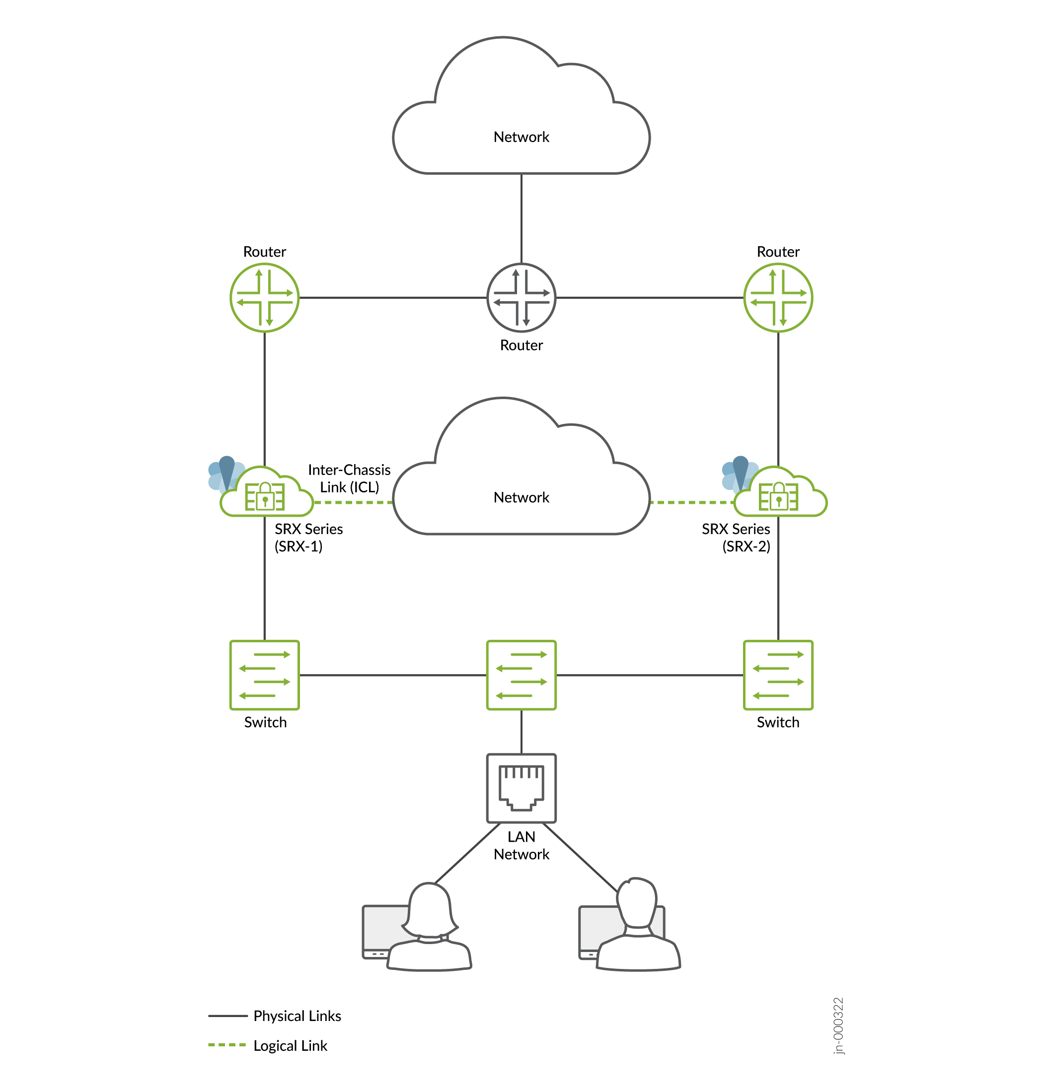
- Hybrid mode (one or more interfaces are connected using a Layer 3 topology and one or more interfaces are connected using a Layer 2 topology) Figure 3: Hybrid Mode
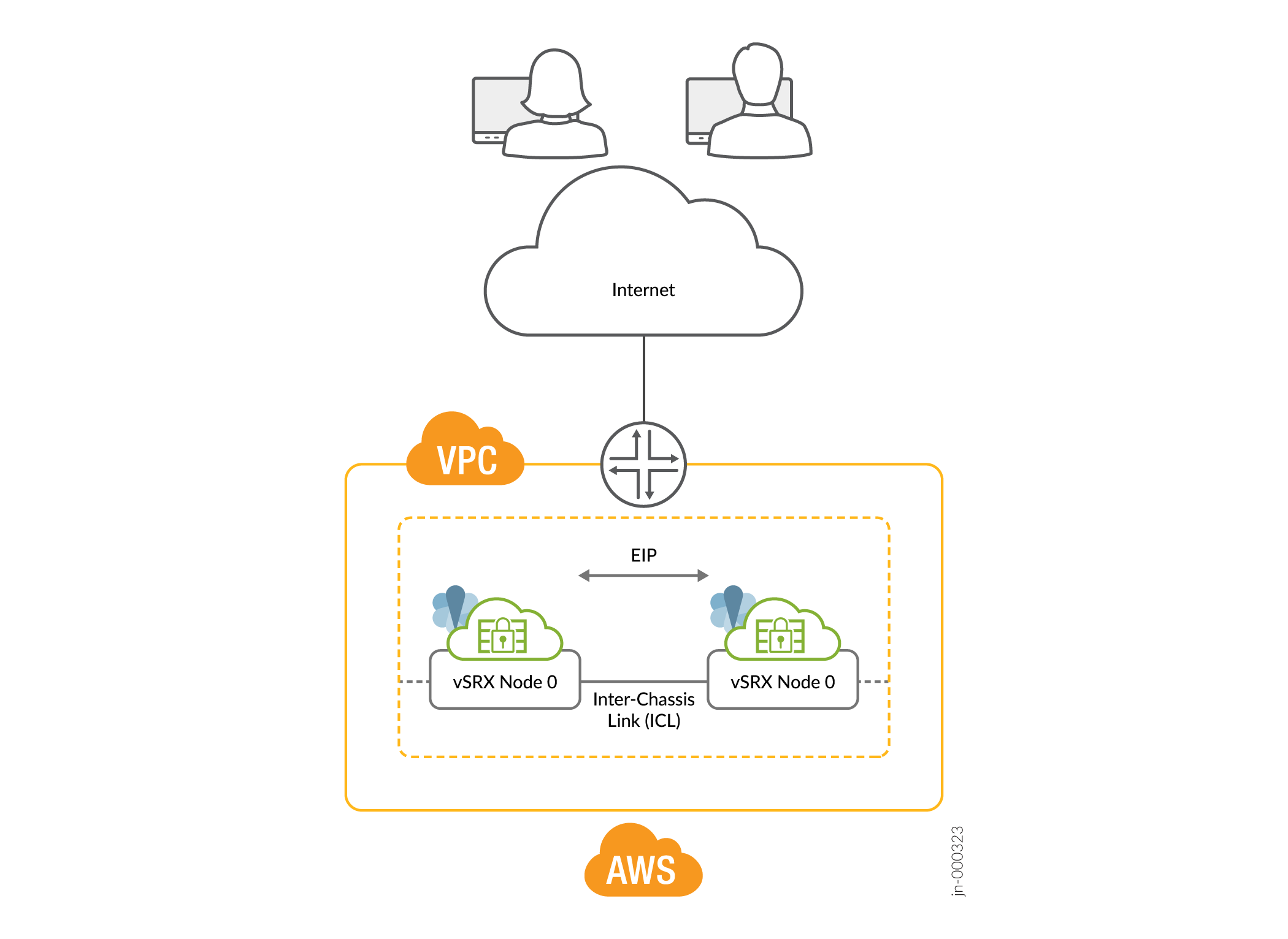
- Public Cloud Deployment Figure 4: Public Cloud Deployment (Example: AWS)
How Two-Node Multinode High Availability Works
In a Multinode High Availability setup, you connect two firewalls to adjacent upstream and downstream routers (for Layer 3 deployments), routers and switches (hybrid deployment), or switches (default gateway deployment) using the revenue interfaces.
The nodes communicate with each other using an interchassis link (ICL). The ICL link uses Layer 3 connectivity to communicate with each other, This communication can take place over a routed network (Layer 3), or a directly connected Layer 2 path. It is recommended to bind the ICL to the loopback interface and have more than one physical link (LAG/LACP) to ensure path diversity for the highest resiliency.
Multinode High Availability operates in active/active mode for data plane and active/backup mode for control plane services. The active firewall hosts the floating IP address and steers traffic towards it using the floating IP address
Multinode High Availability operates in:
- Active/active mode (SRG0) for the security services
- Active/backup mode (SRG1 and above) for security and system services
Floating IP addresses controlled by SRG1 or above moves between the nodes . Active SRG1+ hosts and controls the floating IP address. In failover scenarios, this IP address 'floats' to another active SRG1 based on configuration, system health, or path monitoring decisions. The the newly active SRG1+ can take on the function of a now-standby SRG1 and starts responding to incoming requests.
Figure 5, Figure 6, and Figure 7 show deployments in Layer 3, hybrid, and default gateway modes.
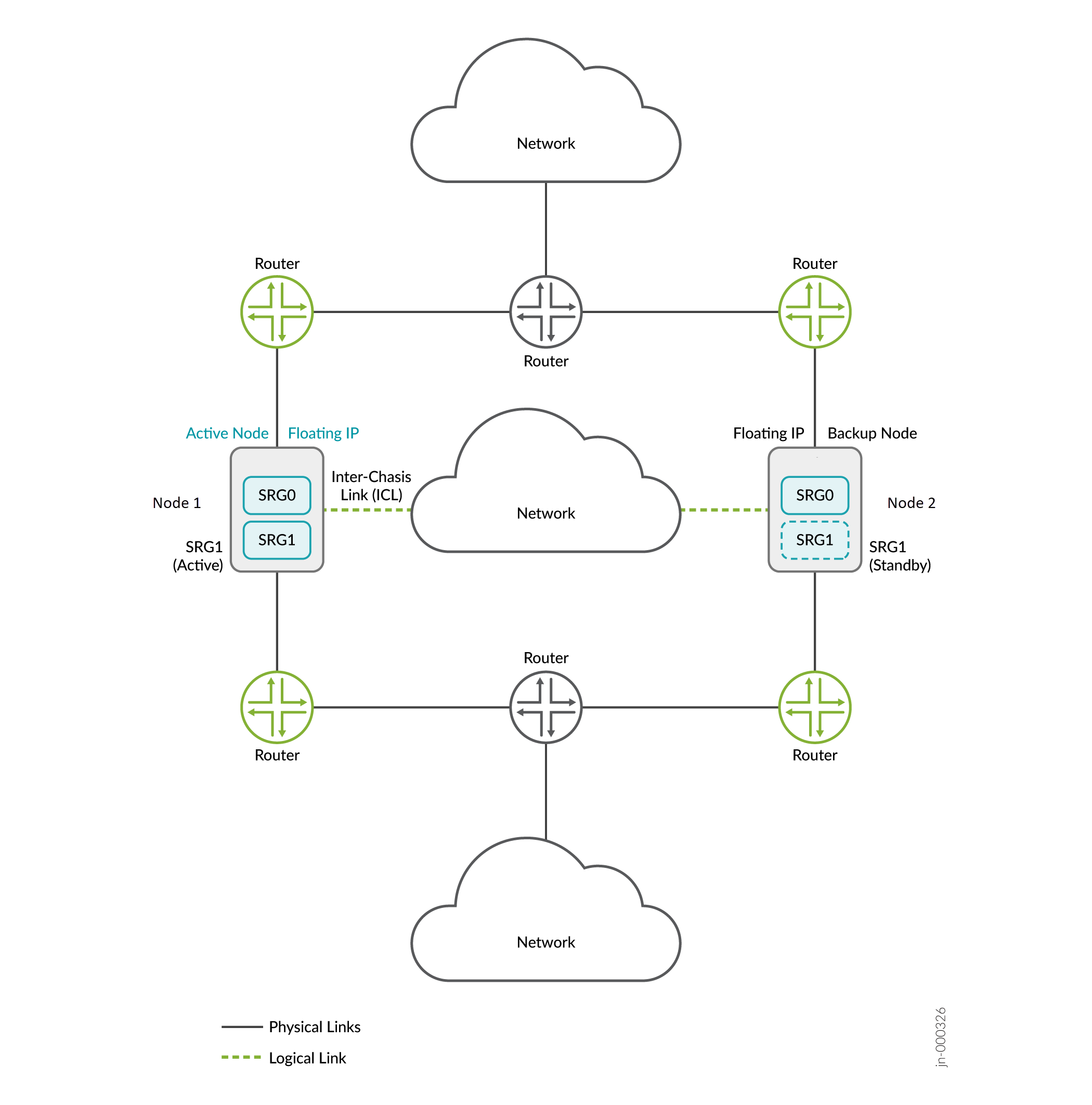
In this topology, two firewalls are part of a Multinode High Availability setup. The setup has Layer 3 connectivity between firewalls and neighboring routers. The devices are running on separate physical Layer 3 networks and are operating as two independent nodes. The nodes shown in the illustration are co-located in the topology. The nodes can also be geographically separated.
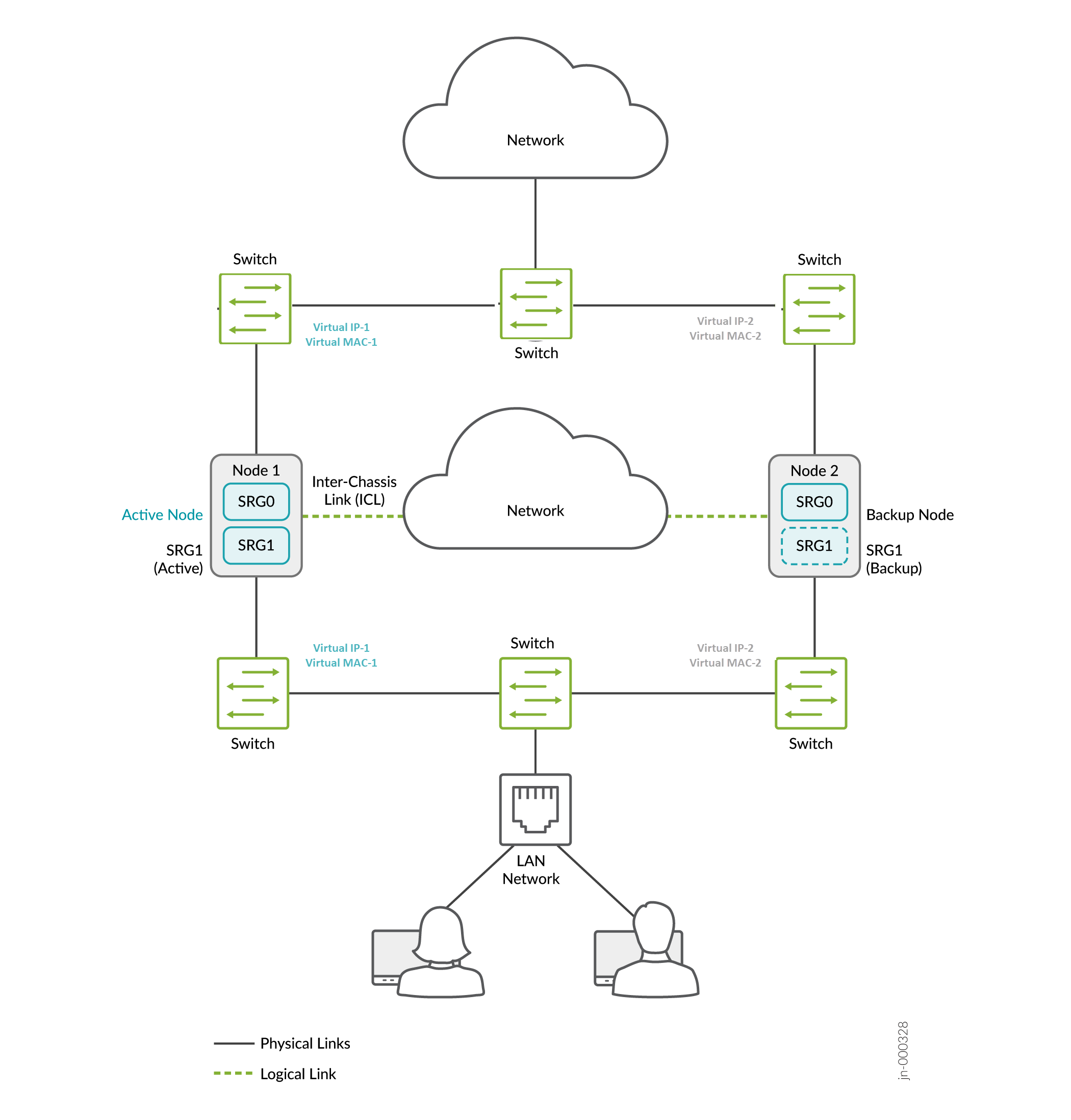
In a typical default gateway deployment, hosts and servers in a LAN are configured with a default gateway of the security device. So the security device must host a virtual IP (VIP) address that moves between nodes based on the activeness. The configuration on hosts remains static, and security device failover is seamless from the hosts' perspective.
You must create static routes or dynamic routing on firewalls to reach other networks not directly connected.
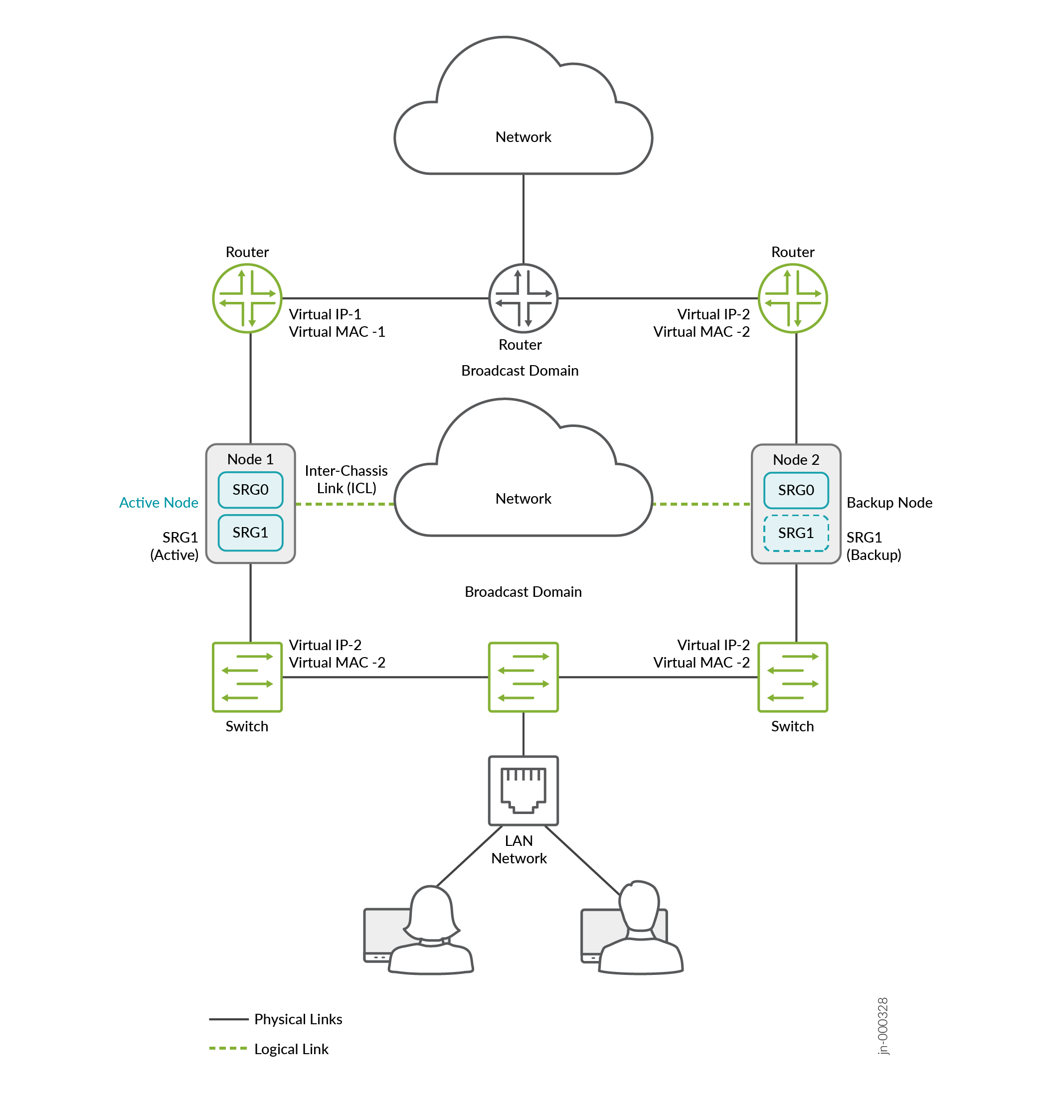
In hybrid mode, a firewall uses a VIP address on the Layer 2 side to draw traffic toward it. You can optionally configure the static ARP for the VIP using the VMAC address to ensure no change in the IP address during the failover
Let's now understand the components and functionality of Multinode High Availability in detail.
- Services Redundancy Groups
- Activeness Determination and Enforcement
- Resiliency and Failover
- Interchassis Link (ICL) Encryption
Services Redundancy Groups
A services redundancy group (SRG) is a failover unit in a Multinode High Availability setup. There are two types of SRGs:
- SRG0—Manages security service from Layer 4-Layer 7 except IPsec VPN services. The SRG0 operates in active mode on both nodes at any point in time. On SRG0, each security session must traverse the node in a symmetric flow, Backup of these flows are fully state-synchronized to the other node,
- SRG1+—Manages IPsec services and virtual IPs for hybrid and default gateway mode and are backed up to the other node. The SRG1 operates in active mode on one node and in backup node on another node.
Figure 8 shows SRG0 and SRG1 in a Multinode High Availability setup.

Figure 9 shows SRG0 and SRG1+ in a Multinode High Availability setup.

Starting in Junos OS Release 22.4R1, you can configure Multinode High Availability to operate in active-active mode with support of multi SRG1s (SRG1+). In this mode, some SRGs remain active on one node and some SRGs remain active on another node. A particular SRG always operates in active-backup mode; it operates in active mode on one node and backup mode on another node. In this case, both the nodes can have the active SRG1 forwarding stateful services. Each node has a different set of floating IP addresses assigned to SRG1+.
Starting in Junos OS Release 22.4R1, you can configure upto 20 SRGs in a Multinode Highavailability setup.
Table 1 explains the behavior of SRGs in a Multinode High Availability setup.
| Related Services Redundancy Group (SRG) | Managed Services | Operates in | Synchronization Type | When Active Node Fails | Configuration Options |
|---|---|---|---|---|---|
| SRG0 | Manages security service L4-L7 except IPsec VPN. | Active/active mode | Stateful synchronization of security services | Traffic processed on the failed node will transition to the healthy node in a stateful manner. |
|
| SRG1+ | Manages IPsec and virtual-IP addresses with associated security services | Active/backup mode | Stateful synchronization of security services | Traffic processed on the failed node will transition to the healthy node in a stateful manner. |
|
When you configure monitoring (BFD or IP or Interface) options on SRG1+, we recommend not to configure the shutdown-on-failure option on SRG0.
Starting in Junos OS Release 23.4R1, the Multinode High Availability setup operates in a combined mode. You don’t have to reboot the system when you add or delete any SRG (SRG0 or SRG1+) configurations.
Activeness Determination and Enforcement
In a Multinode High Availability setup, activeness is determined at the service level, not at the node level. The active/backup state is at the SRG level and the traffic is steered toward the active SRG. SRG0 remains active on both the nodes, whereas SRG1 can remain in active or in backup state in each node
If you prefer a certain node to take over as the active node on boot, you can do one of the followings:
- Configure the upstream routers to include preferences for the path where the node is located.
- Configure activeness priority.
- Allow the node with higher node ID (in case the above two options not configured) to take the active role.
In a Multinode High Availability setup, both the firewalls initially advertise the route for the floating IP address to the upstream routers. There isn’t a specific preference between the two paths advertised by firewalls. However, the router can have its own preferences on one of the paths depending on the configured metrics.
Figure 10 represents the sequence of events for activeness determination and activeness enforcement.
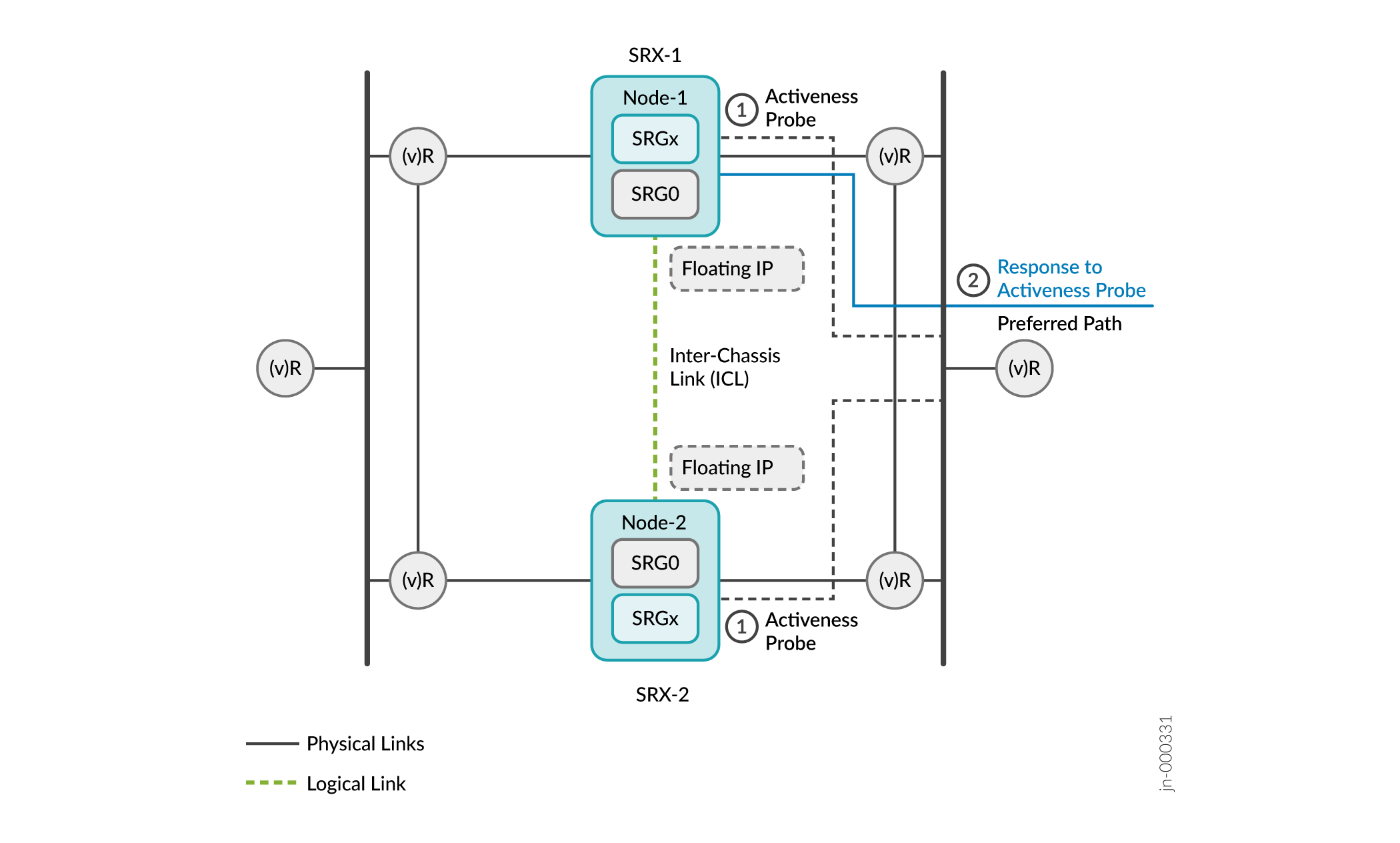
- On boot, devices enter the hold state and start probing continuously. The devices use the floating IP address (activeness-probing source IP address) as the source IP address and IP addresses of the upstream routers as the destination IP address for the activeness determination probe.
The router hosting the probe destination IP address replies to the firewall that is available on its preferred routing path. In the following example, Firewall 1 gets the response from the upstream router.
Figure 11: Activeness Determination and Enforcement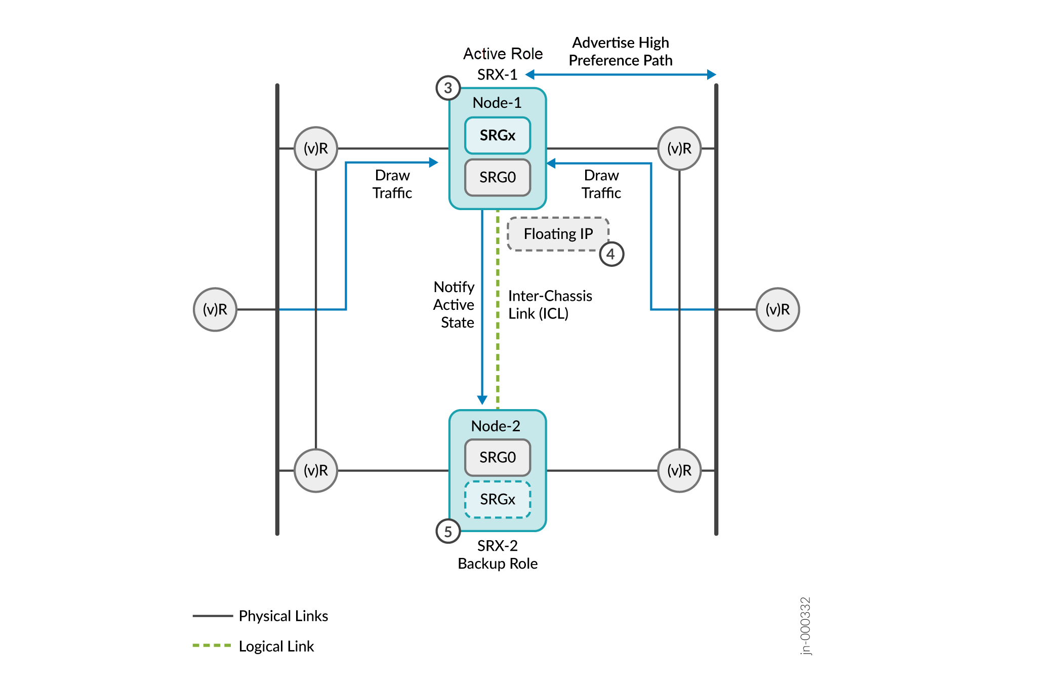
Firewall-1 promotes itself to the active role since it got the probe reply. Firewall-1 communicates its role change to the other device and takes up the active role.
After the activeness is determined, the active node (Firewall-1):
- Hosts the floating IP address assigned to it.
- Advertises the high-preference path to adjacent BGP neighbors.
- Continues to advertise the active (higher) preference path for all remote and local routes to draw the traffic.
- Notifies the active node status to the other node through the ICL.
The other device (Firewall-2) stops probing and takes over the backup role. The backup node advertises the default (lower) priority, ensuring that the upstream routers do not forward any packets to the backup node.
The Multinode High Availability module adds active and backup signal routes for the SRG to the routing table when the node moves to the active role. In case of node failures, the ICL goes down and the current active node releases its active role and removes the active signal route. Now the backup node detects the condition through its probes and transitions to the active role. The route preference is swapped to drive all the traffic towards the new active node.
The switch in the route preference advertisement is part of routing policies configured on firewalls. You must configure the routing policy to include the active signal route with the if-route-exists condition.
- For Default Gateway Deployments
- For Hybrid Deployments
- Activeness Priority and Preemption
- Configuring Activeness Probe Settings
For Default Gateway Deployments
If both the nodes are booting up at the same time, then the Multinode High Availability system uses the configured priority value of an SRG to determine activeness. Activeness enforcement takes place when the node with an active SRG1+ owns the virtual IP (VIP) address and the virtual MAC (VMAC) address. This action triggers Gratuitous ARP (GARP) toward the switches on both sides and results in updating the MAC tables on the switches.
For Hybrid Deployments
Activeness enforcement takes place on the Layer 3 side, when the configured signal route enforce activeness with the corresponding route advertisements. On the Layer 2 side, the firewall triggers a Gratuitous ARP (GARP) to the switch layer and owns the VIP and VMAC addresses
When the failover happens and the old backup node transitions to the active role, the route preference is swapped to drive all the traffic to the new active node.
Activeness Priority and Preemption
Configure the preemption priority (1-254) for SRG1+. You must configure the preemption value on both nodes. The preempt option ensures that the traffic always falls back to the specified node, when the node recovers from a failover.
You can configure activeness priority and preemption for an SRG1+ as in the following sample:
[edit]
user@host# show chassis high-availability
services-redundancy-group 1 {
    preemption;
    activeness-priority 200;
}
See Configuring Multinode High Availability In a Layer 3 Network for the complete configuration example.
As long as the nodes can communicate with each other through the ICL, the activeness priority is honored.
Configuring Activeness Probe Settings
Starting in Junos OS 22.4R1, default gateway (switching) and in hybrid deployments of Multinode High Availability, you can optionally configure activeness probe parameters using the following statements:
[edit]
user@host# set chassis high-availability services-redundancy-group 1 activeness-probe multiplier <>
user@host# set chassis high-availability services-redundancy-group 1 activeness-probe minimal-interval <>
The probe interval sets the time period between the probes sent to the destination IP addresses. You can set the probe interval as 1000 milliseconds.
The multiplier value determines the time period, after which the backup node transitions to active state, if the backup node fails to receive response to the activeness-probes from the peer node.
The default is 2, and the minimum value is 2, and the maximum is 15.
Example: If you configure the multiplier value to two, the backup node will transition to the active state if it does not receive a response to activeness probing request from the peer node after two seconds.
You can configure multiplier and minimal-interval in switching and hybrid deployments.
In hybrid mode deployments, if you've configured the probe destination IP details for activeness determination (by using the activeness-probe dest-ip statement), then do not configure the multiplier and minimal-interval values. Configure these parameters when you are using VIP-based activeness probing.
Resiliency and Failover
The Multinode High Availability solution supports redundancy at the service level. Service-level redundancy minimizes the effort needed to synchronize the control plane across the nodes.
After the Inter‑Chassis Link (ICL) is up, the MNHA nodes negotiate SRG parameters and transition to active and backup roles based on the configured priority. The node with the higher priority becomes the active node and publishes its state over the ICL to the peer node. The peer node then moves to the backup state as long as its health status remains valid.
When the ICL goes down, split‑brain activeness probing is triggered from the backup node. In routing mode, the backup node probes the upstream and downstream router IPs using a floating anycast IP as the source. This IP is typically hosted on a loopback interface and is advertised by the active SRX Series Firewall with a better metric. In switching or hybrid deployments, the backup node triggers ICMP or BFD probes to an IP hosted on the active SRX Series Firewall on the LAN side.
The split‑brain probing logic is used to determine whether the active node is still operational and forwarding traffic on the active path. If the split‑brain probes are successful, the backup device continues to remain in the backup state. If the probes fail—for example, when the active node becomes ineligible or reboots—the backup node transitions to the active role and steers traffic onto the active path.
The SRG1 of the previous backup node now transitions to the active state and continues to operate seamlessly. When the transition happens, the floating IP address is assigned to the active SRG1. In this way, the IP address floats between the active and backup nodes and remains reachable to all the connected hosts. Thus, traffic continues to flow without any disruption.
Services, such as IPsec VPN, that require both control plane and data plane states are synchronized across the nodes. Whenever an active node fails for this service function, both control plane and data plane fail over to the backup node at the same time.
The nodes use the following messages to synchronize data:
- Routing Engine to Routing Engine control application messages
- Routing Engine configuration-related messages
- Data plane RTO messages
Interchassis Link (ICL) Encryption
In Multinode High Availability, the active and backup nodes communicate with each other using an interchassis link (ICL) connected over a routed network or connected directly. The ICL is a logical IP link and it is established using IP addresses that are routable in the network.
Nodes use the ICL to synchronize control plane and data plane states between them. ICL communication could go over a shared or untrusted network and packets sent over the ICL may traverse a path that is not always trusted. Therefore, you must secure the packets traversing the ICL by encrypting the traffic using IPsec standards.
IPsec protects traffic by establishing an encryption tunnel for the ICL. When you apply HA link encryption, the HA traffic flows between the nodes only through the secure, encrypted tunnel. Without HA link encryption, communication between the nodes may not be secure.
To encrypt the HA link for the ICL:
- Install the Junos IKE package on your firewall by using the following command:
request system software add optional://junos-ike.tgz. - Configure a VPN profile for the HA traffic and apply the profile for both the nodes. The IPsec tunnel negotiated between the firewalls uses the IKEv2 protocol.
Ensure you have included the statement ha-link-encryption in your IPsec VPN configuration. Example: user@host# set security ipsec vpn vpn-name ha-link-encryption.
Following settings are recommended for an ICL:
Use ports and network which is less likely to be saturated.
Not to use the dedicated HA ports (control and fabric ports, if available on your firewall)
Bind the ICL to the loopback interface (lo0) or an aggregated Ethernet interface (ae0) and have more than one physical link (LAG/LACP) that ensure path diversity for highest resiliency.
You can use a revenue Ethernet port on the firewalls to setup an ICL connection. Ensure that you separate the transit traffic in revenue interfaces from the high availability (HA) traffic.
Checks have been introduced to restrict the configuration of tunnel MTU for HA link encryption tunnels in a Multinode High Availability setup. The check ensures that the end-to-end MTU for HA links using IPv6 encryption meets the minimum requirement of 2000 bytes, helping maintain optimal performance and reliability during high availability operations.
For example, if your configuration includes the following stanza where tunnel-mtu is less than 2000, you'll receive a commit check error: user@host# set security ipsec vpn L3HA_IPSEC_VPN tunnel-mtu <bytes>
- In general, you can use Aggregated Ethernet (AE) or a revenue Ethernet port on the security devices to setup an ICL connection.
- We recommend setting MTU of 1514 and allow the following services on the security zone associated with interfaces used for ICL
IKE, high-availability, SSH
Protocols depending on the routing protocol you need.
BFD to monitor the neighboring routes.
See Configuring Multinode High Availability for more details.
PKI-Based Link Encryption for ICL
Starting in Junos OS Release 22.3R1, MNHA supports PKI-based link encryption for interchassis link (ICL). As a part of this support, you can now generate and store node-specific PKI objects such as local keypairs, local certificates, and certificate-signing requests on both nodes. The objects are specific to local nodes and are stored in the specific locations on both nodes.
The node local objects enable you to distinguish between PKI objects that are used for ICL encryption and PKI objects used for IPsec VPN tunnel created between two endpoints.
You can use the following commands run on local node to work with node-specific PKI objects.
| Generating a private/public key pair for a local node | |
| Generating and enrolling a local digital certificate in a local node |
|
| Clear node-specific certificates | |
| Display node-specific local certificates and certificate requests. |
On your security device in Multinode High Availability, if you've configured the automatic re-enrollment option and if the ICL goes down at the time of re-enrollment trigger, both the devices start enrolling the same certificate separately with the CA server and download the same CRL file. Once Multinode High Availability re-establishes the ICL, the setup uses only one local certificate. You must synchronize the certificates from the active node to backup node using the user@host> request security pki sync-from-peer command on the backup node.
If you don't synchronize the certificates, the certificate mismatch issue between peer nodes persists till the next re-enrollment.
Optionally you can enable TPM (Trusted Platform module) on both nodes before generating any keypairs on the nodes. See Using Trusted Platform Module to Bind Secrets on SRX Series devices.
Split-Brain Detection and Prevention
Split-brain detection or activeness conflict happens when the ICL between two Multinode High Availability nodes is down and both node cannot reach each other to gather the status of peer node anymore.
- ICMP-Based Split-Brain Probing
- BFD-Based Split-Brain Probing
- Configure Split-Brain Probing
- Logical Systems and Tenant Systems Support
ICMP-Based Split-Brain Probing
Consider a scenario where two security devices are part of Multinode High Availability setup. Lets consider Firewall-1 as local node and Firewall-2 remote node. The local node is currently in active role and hosting floating IP address to steer traffic towards it. The upstream router has higher priority path for the local node.
When the ICL between the nodes goes down, both nodes initiate a activeness determination probe (ICMP probe). The nodes use the floating IP address (activeness determination IP address) as source IP address and IP addresses of the upstream routers as destination IP address for the probes.
Case 1: If Active Node is Up
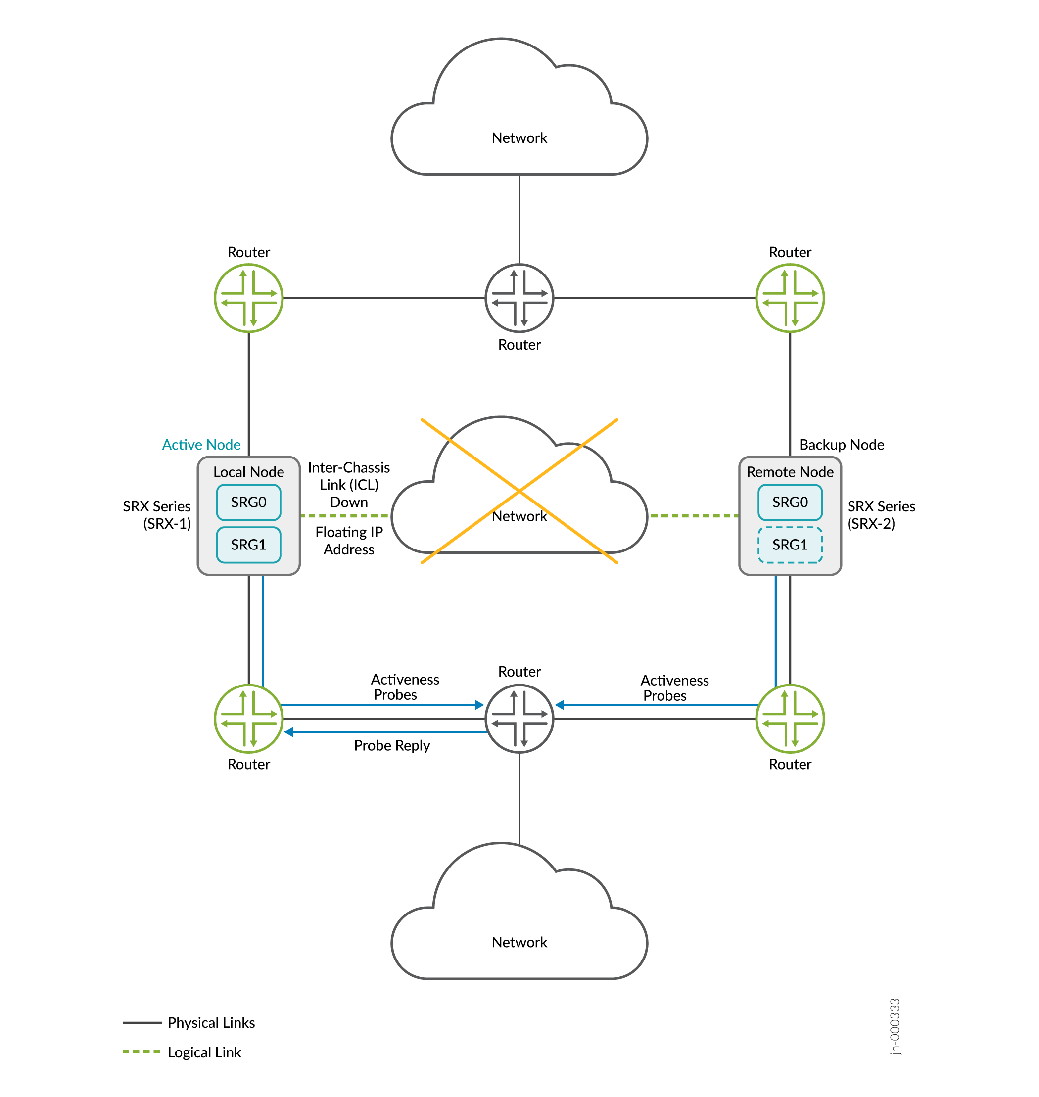
- The upstream router, that hosts the probe destination IP address, receives the ICMP probes from both nodes.
- Upstream router replies to only to the active node; because it's configuration has higher preference path for the active node
- The active node retains the active role.
If Active Node is Down:
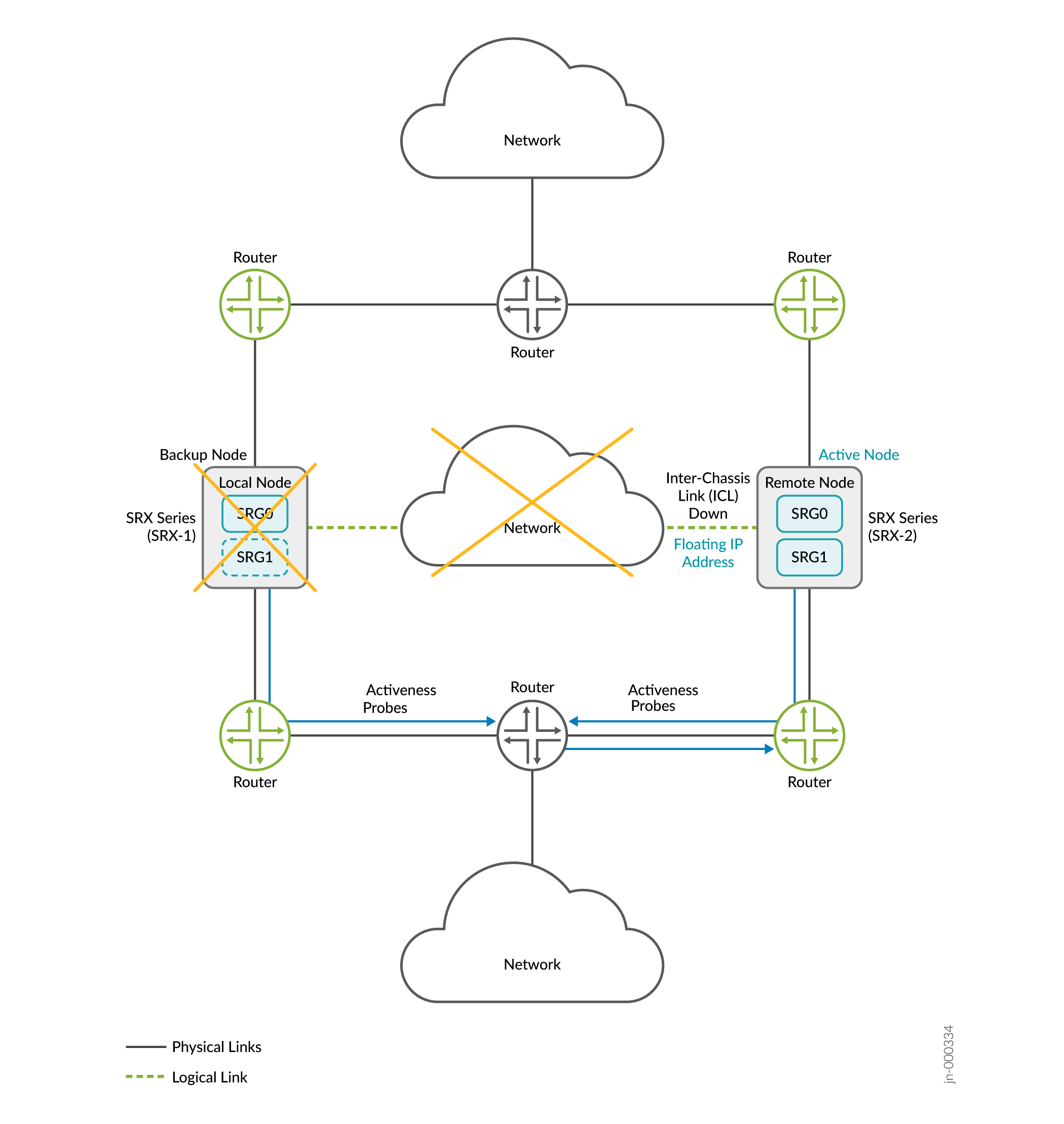
- The remote node restarts the activeness determination probes.
- The router hosting the probe destination IP address has lost its higher preference path (of former active node) and replies to the remote node.
- The probe result is a success for the remote node and the remote node transitions to the active state.
- As demonstrated in the above cases, activeness determination probes and the configuration of higher path preference in the upstream router ensures one node always stays in the active role and prevents split-brain taking place.
BFD-Based Split-Brain Probing
In Junos OS Release 23.4R1, SRX Series Firewalls in MNHA support BFD-based split-brain probing for default gateway and hybrid mode of deployments..
Interchassis Link (ICL) failure can often be attributed to two key factors: network disruptions or inconsistent configurations. You can use activeness probe to determine the node that can take active role for each SRG1+. Based on the probe result, one of the node transitions to the active state and this action prevents spilt-brain scenario.
With BFD-based split-brain probing, you can now have more granular control on the probes as you can define the interface, minimal-interval, and multipliers. In the BFD-based split-brain probing, the probing starts immediately after an SRG is configured and starts functioning. In the default ICMP-based split-brain probing, the probing starts only after ICL link goes down.
BFD-based probing is proactive in the following ways to ensures a quicker response to prevent split-brain scenarios:
The probing initiates directly post an SRG configuration.
If both ICL BFD and split-brain probe break at the same time, the backup node immediately assumes the active role and takes over the VIP.
This ensures a quicker response to prevent split-brain scenarios.
How it Works?
When the ICL is down and both devices are starting up, the nodes initially enter a HOLD state and wait for the peer node comes up and connect. For any reason if the other node doesn’t come up, the system initiates split brain probes to the IP addresses hosted on different device in network. If the process completes successfully, one node transitions to active and the other to backup. Before probe success, if any path monitoring failure/internal hardware monitor failure occurs, then both nodes become Ineligible to prevent a split-brain scenario.
If the split-brain probe fails for any reason, the nodes will remain in the HOLD state and continue probing. The split-brain probe IP must always be available on the network. Except for IPsec, all other application traffic will not experience loss on firewall as long as routing is available, even in the HOLD state.
When both nodes are in Hold or Ineligible state, no traffic will be forwarded until the node becomes active/backup again.
Note:
- Split brain is based on the activeness probes different from path monitor probes. It only triggered when ICL/communication is broken b/w MNHA nodes
- When the Interchassis Link (ICL) between nodes is broken, both nodes initiate split brain probes. The active node retains mastership as long as its probe does not fail. It is recommended to host the probing IP on a path that ensures continuous reachability, provided the node is healthy. A state change is triggered only if the probe from the current active node fails and the probe from the current backup node succeeds.
- In switching and hybrid modes, traffic steering uses the Virtual IP (VIP), which only works in the ACTIVE state. The system should not stay in the HOLD state after the hold timer expires, as it will probe the MNHA peer to resolve the split-brain situation.
Difference in ICMP-Based and BFD-Based Probing
The following table shows differences in ICMP-based probing and BFD-based probing for split-brain detection.
Parameters |
ICMP-Based Probing |
BFD-Based Probing |
|---|---|---|
| Deployment type | Routing, Hybrid | Switching, Hybrid |
| Probe type | ICMP packet | BFD packet, single-hop BFD |
| Minimal interval | 1000 ms | Firewall's minimal BFD interval depends on platform. For example: Firewalls with SPC3, interval is 100 ms. For some other firewalls, the interval is 300 ms. |
| SRG backup node probes | Yes | Yes |
| SRG active node probes | No | Yes |
| Probe source | Anycast loopback IP | Node IP |
| SRG split-brain resolving when ICL down | Only when ICL goes down | After an SRG is configured |
The following figure shows configuration options for ICMP-based probing and BFD-based probing for split-brain detection.
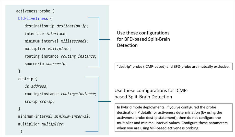
ICMP-based probing and BFD-based probes are mutually exclusive.
In hybrid mode and default gateway deployments, you can configure the activeness-probe interval and threshold at following two levels:
Global-level which is applicable to ICMP-based split-brain probing
BFD-Liveliness level which is specific to BFD split-brain probe. When you configure BFD-based probing, do not configure global
minimum-intervalandmultiplieroptions underactiveness-probestatement.
To configure activeness probe for default gateway deployments, use the primary virtual IP (VIP1) address interface on both nodes (local and peer) to set up your activeness probe. The destination IP is from the peer node, and the source IP is from your local node. Both VIPs must have the same index value. The IP addresses must be the inet addresses assigned to the LAN interface of the firewall.
Configure Split-Brain Probing
You can configure split-brain probing on a Multinode Node High Availability setup in the following ways:Routing and Hybrid mode —If you've configured the probe destination IP details for activeness determination (by using the
activeness-probe dest-ipstatement), then do not configure the multiplier and minimal-interval values. Configure these parameters when you are using VIP-based activeness probing.[edit] [set chassis high-availability services-redundancy-group 1 activeness-probe dest-ip <neighbor_ip_address> src-ip <srx_anycast_IP>]
Hybrid and switching mode—Layer 2 split-brain probing using ICMP. Use the probe type ICMP and set interval and timeout threshold using the following statement:
[edit]
[set chassis high-availability services-redundancy-group 1 activeness-probe
minimum-interval <interval> multiplier <integer>
Hybrid and switching mode—Layer 2 split-brain probing using BFD. Use the probe type BFD and set the timeout threshold that can be sub-second based on the BFD minimum-interval configured.
[edit]
[set chassis high-availability services-redundancy-group 1 activeness-probe
bfd-liveliness source-ip <ip-address> destination-ip <ip-address> interface <vip1_ifl_interface>
minimum-interval <interval> multiplier <integer>
Figure 15 shows the sample topology. Two firewalls are connected to adjacent routers on trust and untrust side forming a BGP neighborship. An encrypted logical interchassis link (ICL) connects the nodes over a routed network. The nodes communicate with each other using a routable IP address (floating IP address) over the network.
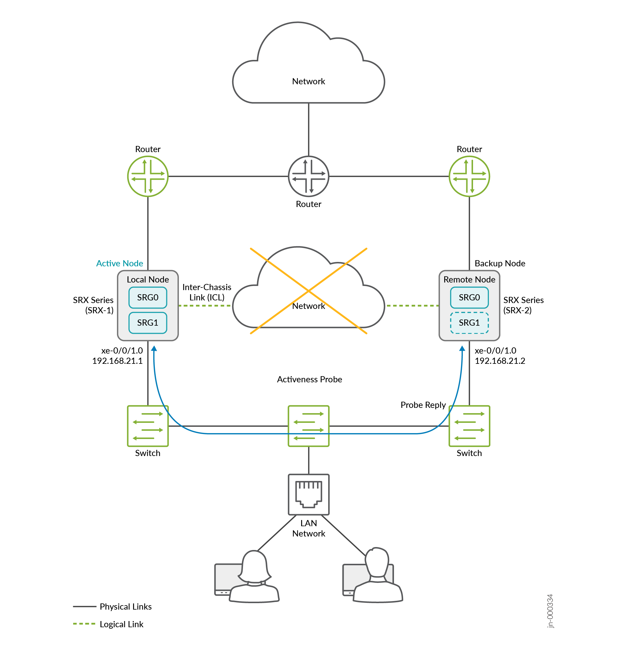
Lets consider Firewall-1 as a local node and Firewall-2 a remote node. The local node is currently in active role and the upstream router has higher priority path for the local node.
Source IP address: Use the primary physical IP address of the local node’s interface that hosts the virtual IP (VIP) for the SRG.
Destination IP address: Use the primary physical IP address of the peer node’s corresponding interface that hosts the same VIP.
Interface: Specify the interface associated with the VIP on the local node.
The VIP referenced here represents the VIP pair with the same VIP index configured on both nodes. The VIP index does not have to be VIP1; any matching VIP index can be used
For BFD-based split-brain probing, you must:
- Configure matching source and destination IP addresses for the same SRG on both nodes.
- Configure the
activeness-priorityoption to determine active node as a result of split-brain probing.
The following table shows how Multinode High Availability setup resolves split-brain situation with BFD-based probing when the ICL is down. Depending on node states and probe results, Multinode High Availability system selects the node to take up the active role.
In this example, assume that SRG1 of node 1 has the higher activeness-priority.
| State of Node 1 | Probing State of Node 1 | State of Node 2 | Probing State of Node 2 | Node Transitioning to SRG1 Active State |
| Active | Down | Ineligible | No probing | Node 1 |
| Active | Up | Backup | Up | Node 1 |
| Active | Up | Active | Up | Node 1 (Tie breaker) |
| Backup | Down | Ineligible | No probing | Node 1 |
| Backup | Up | Backup | Up | Node 1 (Tie breaker) |
| Backup | Up | Active | Up | Node 2 |
| Ineligible | No probing | Ineligible | No probing | Neither Node |
| Ineligible | No probing | Backup | Down | Node 2 |
| Ineligible | No probing | Active | Down | Node 2 |
Sample Configuration
Node 1:
set chassis high-availability services-redundancy-group 1 activeness-priority 1 set chassis high-availability services-redundancy-group 1 activeness-probe bfd-liveliness destination-ip 192.168.21.2
set chassis high-availability services-redundancy-group 1 activeness-probe bfd-liveliness destination-ip 192.168.21.2 source-ip 192.168.21.1
set chassis high-availability services-redundancy-group 1 activeness-probe bfd-liveliness destination-ip 192.168.21.2 interface xe-0/0/1.0
set chassis high-availability services-redundancy-group 1 activeness-probe bfd-liveliness destination-ip 192.168.21.2  minimum-interval 300
set chassis high-availability services-redundancy-group 1 activeness-probe bfd-liveliness destination-ip 192.168.21.2 multiplier 3
Node 2:
set chassis high-availability services-redundancy-group 1 activeness-priority 200
set chassis high-availability services-redundancy-group 1 activeness-probe bfd-liveliness destination-ip 192.168.21.1
set chassis high-availability services-redundancy-group 1 activeness-probe bfd-liveliness destination-ip 192.168.21.1 source-ip 192.168.21.2
set chassis high-availability services-redundancy-group 1 activeness-probe bfd-liveliness destination-ip 192.168.21.1 interface xe-0/0/1.0
set chassis high-availability services-redundancy-group 1 activeness-probe bfd-liveliness destination-ip 192.168.21.1 minimum-interval 300
set chassis high-availability services-redundancy-group 1 activeness-probe bfd-liveliness destination-ip 192.168.21.1 multiplier 3
Verification
-
Use the
(BFD-based Probing)show chassis high-availability services-redundancy-group 1command to see the type of split-brain probe configured on the device.user@host> show chassis high-availability services-redundancy-group 1 .. Split-brain Prevention Probe Info: DST-IP: 192.168.21.2 SRC-IP: N/A Routing Instance: default Type: BFD Probe Interval: 300ms Multiplier: 3 Status: RUNNING Result: REACHABLE Reason: N/A ..user@host> show chassis high-availability services-redundancy-group 1 .. Split-brain Prevention Probe Info: DST-IP: 192.168.21.2 SRC-IP: 192.168.21.1 Routing Instance: default Type: ICMP Probe Status: NOT RUNNING Result: N/A Reason: N/A .. Use the
show bfd sessioncommand to see if BFD-based probe status.user@host> show bfd session Detect Transmit Address State Interface Time Interval Multiplier 192.168.0.2 Up 0.300 0.100 3 192.168.21.2 Up xe-0/0/1.0 0.300 0.100 3 1 sessions, 1 clients Cumulative transmit rate 0.5 pps, cumulative receive rate 0.0 ppsIn the sample, you can notice that BFD-based split-brain probing is running for interface xe-0/0/1.0.
Use the
show chassis high-availability services-redundancy-group 1command to get the details pf BFD-based probes.user@host> show chassis high-availability services-redundancy-group 1 SRG failure event codes: BF BFD monitoring IP IP monitoring IF Interface monitoring CP Control Plane monitoring Services Redundancy Group: 1 Deployment Type: ROUTING Status: ACTIVE Activeness Priority: 200 Preemption: ENABLED Process Packet In Backup State: NO Control Plane State: READY System Integrity Check: N/A Failure Events: NONE Peer Information: Peer Id: 1 Status : N/A Health Status: SRG NOT CONFIGURED Failover Readiness: UNKNOWN Activeness Remote Priority: 100
Logical Systems and Tenant Systems Support
Logical systems for Junos firewalls enable you to partition a single device into secure contexts and A tenant system logically partitions the physical firewall into separate and isolated logical firewall.
A tenant system logically partitions the physical firewall into separate and isolated logical firewall. Although similar to logical systems, tenant systems have much higher scalability and fewer routing features.
Firewalls in Multinode High Availability setup support logical systems and tenant systems on services redundancy group 0 (SRG0).
The behavior of a Multinode High Availability setup with firewalls running logical systems is the same as that of a setup where the nodes do not run logical systems. There is no difference in the events that trigger a node failover. Specifically, if the interface monitoring is enabled under SRG0 and a link associated with a single logical system fails (which is being monitored), the device fails over to another node. This failover occurs through route preference advertisements in the Multinode High Availability setup.
Before setting up the logical or tenant systems, you must configure the Multinode High Availability. Each node in the high availability setup must have an identical configuration. Ensure that the logical systems or tenant systems' name, profile, and corresponding security features, or interfaces within the logical systems or tenant systems are same. All logical or tenant system configurations are synchronized and replicated between the two nodes.
Use Junos configuration groups to configure features and functions, and synchronize the configuration by using the [edit system commit peers-synchronize] option in your Multinode High Availability setup. See Configuration Synchronization Between Multinode High Availability Nodes.
When using firewalls with logical systems in an Multinode High Availability, you must purchase and install the same number of licenses for each node in the setup.
For more information, see Logical Systems and Tenant Systems User Guide for Security Devices.
Change History Table
Feature support is determined by the platform and release you are using. Use Feature Explorer to determine if a feature is supported on your platform.