Example: Configure Multinode High Availability on SRX Series Firewalls in a Layer 3 Network
This example shows how to configure and verify Multinode High Availability setup in Layer 3 deployment.
Overview
In multinode High Availability, participating SRX Series Firewalls operate as independent nodes in a Layer 3 network. The nodes are connected to adjacent infrastructure belonging to different networks. An encrypted logical interchassis link (ICL) connects the nodes over a routed network. Participating nodes backup each other to ensure a fast synchronized failover in case of system or hardware failure.
In Multinode High Availability, activeness is determined at the services redundancy group (SRG) level. The SRX Series Firewall, on which the SRG1 is active, hosts the floating IP address and steers traffic towards it using the floating IP address. During a failover, the floating IP address moves from the old active node to the new active node and continues the communication client devices.
Example Prerequisites
|
Software requirements |
|
Before You Begin
|
Benefits |
More Details |
|
Know more |
|
|
Learn more |
Functional Overview
|
Technologies used |
|
|
Primary verification tasks |
|
Topology Overview
Figure 1 shows the topology used in this example.
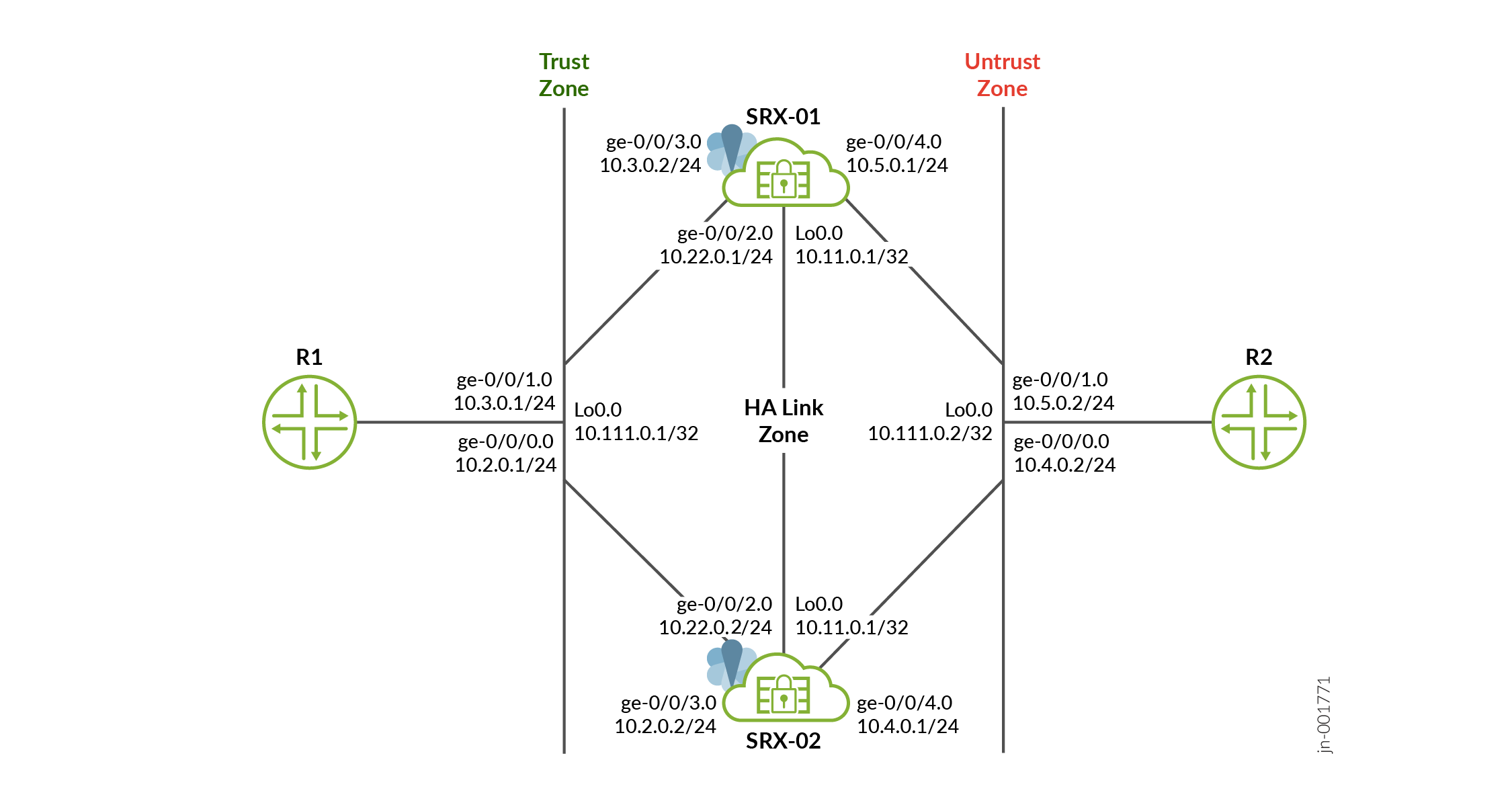
In this Layer 3 multinode high availability (MNHA) deployment, two SRX firewalls (SRX‑01 and SRX‑02) operate as independent routing nodes connected to upstream (R2) and downstream (R1) routers over routed interfaces.
- Each SRX has its own interface IP addresses on the trust and untrust sides.
- The nodes are interconnected through an interchassis link (ICL) over a routed network (HA link).
- A floating loopback IP address (10.11.0.1/32) is configured on both nodes and is owned by the active node in the services redundancy group (SRG).
- Traffic from R1 (trust side) and R2 (untrust side) is routed to the active node based on routing decisions (for example, BGP policies).
- The active node forwards traffic, while the backup node remains ready to take over.
- During a failover:
- The floating IP moves to the backup node.
- Routing updates (for example, via BGP metrics) redirect traffic to the new active node.
- Traffic continues with minimal disruption.
In a typical high availability deployment, you have multiple routers and switches on the northbound and southbound sides of the network. For this example, we are using two routers on both sides of SRX Series Firewalls.
In this example, you'll establish high availability between the SRX Series Firewalls and secure the tunnel traffic by enabling HA link encryption.
Table 1 and Table 2 show the details on interfaces configuration used in this example.
| Device | Interface | Zone | IP Address | Configured For |
|---|---|---|---|---|
SRX-01 |
lo0.0 |
Untrust |
10.11.0.1/32 |
Floating IP address IKE Gateway address |
|
ge-0/0/2.0 |
HA Link |
10.22.0.1/24 |
Connecting ICL |
|
|
ge-0/0/4.0 |
Untrust |
10.5.0.1/24 |
Connects to R2 router |
|
|
ge-0/0/3.0 |
Trust |
10.3.0.2/24 |
Connects to R1 router |
|
SRX-02 |
lo0.0 |
Untrust |
10.11.0.1/32 |
Floating IP address |
|
ge-0/0/2.0 |
HA Link |
10.22.0.2/24 |
Connecting ICL |
|
|
ge-0/0/3.0 |
Trust |
10.2.0.2/24 |
Connects to R1 router |
|
|
ge-0/0/4.0 |
Untrust |
10.4.0.1/24 |
Connects to R2 router |
| Device | Interface | IP Address | Configured For |
|---|---|---|---|
| Router 1 (R1) | lo0 |
10.111.0.1/32 |
Loopback interface address of R1 |
|
ge-0/0/1.0 |
10.3.0.1/24 |
Connects to |
|
|
ge-0/0/0.0 |
10.2.0.1/24 |
Connects to |
|
| Router 2 (R2) | lo0 |
10.111.0.2/32 |
Loopback interface address of R2 |
|
ge-0/0/0.0 |
10.4.0.2/24 |
Connects to |
|
|
ge-0/0/1.0 |
10.5.0.2/24 |
Connects to |
Configure Firewalls
Verification
Use the show commands to confirm that the configuration is working properly.
| Command | Verification Task |
|---|---|
|
|
Display details of the MNHA status on your security device including health status of the peer node. |
show chassis high-availability
                                    services-redundancy-group
|
Display status service redundancy groups in your MNHA setup. |
- Check Multinode High Availability Setup
- Check Multinode High Availability Service Redundancy Groups
- Verify Interchassis Link (ICL) Encryption Status
Check Multinode High Availability Setup
Purpose
View and verify the details of the Multinode High Availability setup configured on your security device.
Action
From operational mode, run the following command:
SRX-01
user@srx-01> show chassis high-availability information
Node failure codes:
    HW  Hardware monitoring    LB  Loopback monitoring
    MB  Mbuf monitoring        SP  SPU monitoring
    CS  Cold Sync monitoring   SU  Software Upgrade

Node Status: ONLINE
Grid-id: 0
Local-id: 1
Local-IP: 10.22.0.1
HA Peer Information:

    Peer Id: 2        IP address: 10.22.0.2     Interface: ge-0/0/2.0
    Routing Instance: default
    Encrypted: YES    Conn State: UP
    Configured BFD Detection Time: 5 * 400ms
    Cold Sync Status: COMPLETE

SRG failure event codes:
    BF  BFD monitoring
    IP  IP monitoring
    IF  Interface monitoring
    CP  Control Plane monitoring

Services Redundancy Group: 1
        Deployment Type: ROUTING
        Status: ACTIVE
        Activeness Priority: 200
        Preemption: ENABLED
        Process Packet In Backup State: NO
        Control Plane State: READY
        System Integrity Check: N/A
        Failure Events: NONE
        Peer Information:
          Peer Id: 2
          Status : BACKUP
          Health Status: HEALTHY
          Failover Readiness: READY
SRX-02
user@srx-02> show chassis high-availability information
Node failure codes:
    HW  Hardware monitoring    LB  Loopback monitoring
    MB  Mbuf monitoring        SP  SPU monitoring
    CS  Cold Sync monitoring   SU  Software Upgrade

Node Status: ONLINE
Grid-id: 0
Local-id: 2
Local-IP: 10.22.0.2
HA Peer Information:

    Peer Id: 1        IP address: 10.22.0.1     Interface: ge-0/0/2.0
    Routing Instance: default
    Encrypted: YES    Conn State: UP
    Configured BFD Detection Time: 5 * 400ms
    Cold Sync Status: COMPLETE

SRG failure event codes:
    BF  BFD monitoring
    IP  IP monitoring
    IF  Interface monitoring
    CP  Control Plane monitoring

Services Redundancy Group: 1
        Deployment Type: ROUTING
        Status: BACKUP
        Activeness Priority: 1
        Preemption: DISABLED
        Process Packet In Backup State: NO
        Control Plane State: READY
        System Integrity Check: COMPLETE
        Failure Events: NONE
        Peer Information:
          Peer Id: 1
          Status : ACTIVE
          Health Status: HEALTHY
          Failover Readiness: N/A
Meaning
Verify these details from the command output:
-
Local node and peer node details such as IP address and ID.
-
The field
Encrypted: YESindicates that the traffic is protected. -
The field
Deployment Type: ROUTINGindicates a Layer 3 mode configuration—that is, the network has routers on both sides. -
The field
Services Redundancy Group: 1indicate the status of the SRG1 as active or backup on that node.
Check Multinode High Availability Service Redundancy Groups
Purpose
Verify that the SRGs are configured and working correctly.
Action
From operational mode, run the following command:
SRX-01
user@srx-01> show chassis high-availability services-redundancy-group 1
SRG failure event codes:
    BF  BFD monitoring
    IP  IP monitoring
    IF  Interface monitoring
    CP  Control Plane monitoring

Services Redundancy Group: 1
        Deployment Type: ROUTING
        Status: ACTIVE
        Activeness Priority: 200
        Preemption: ENABLED
        Process Packet In Backup State: NO
        Control Plane State: READY
        System Integrity Check: N/A
        Failure Events: NONE
        Peer Information:
          Peer Id: 2
          Status : BACKUP
          Health Status: HEALTHY
          Failover Readiness: READY

        Signal Route Info:
          Active Signal Route:
          IP: 10.39.1.1
          Routing Instance: default
          Status: INSTALLED

          Backup Signal Route:
          IP: 10.39.1.2
          Routing Instance: default
          Status: NOT INSTALLED

        Split-brain Prevention Probe Info:
          DST-IP: 10.111.0.1
          SRC-IP: 10.11.0.1
          Routing Instance: default
          Type: ICMP Probe
          Status: NOT RUNNING
          Result: N/A           Reason: N/A


        BFD Monitoring:
      Status: UP

          SRC-IP: 10.5.0.1     DST-IP: 10.5.0.2
          Routing Instance: default
          Type: SINGLE-HOP
          IFL Name: ge-0/0/4.0
          State: UP


IP SRGID Table:
        SRGID    IP Prefix                                   Routing Table
        1        NULL                                        NULL
SRX-02
user@srx-02> show chassis high-availability services-redundancy-group 1
SRG failure event codes:
    BF  BFD monitoring
    IP  IP monitoring
    IF  Interface monitoring
    CP  Control Plane monitoring

Services Redundancy Group: 1
        Deployment Type: ROUTING
        Status: BACKUP
        Activeness Priority: 1
        Preemption: DISABLED
        Process Packet In Backup State: NO
        Control Plane State: READY
        System Integrity Check: COMPLETE
        Failure Events: NONE
        Peer Information:
          Peer Id: 1
          Status : ACTIVE
          Health Status: HEALTHY
          Failover Readiness: N/A

        Signal Route Info:
          Active Signal Route:
          IP: 10.39.1.1
          Routing Instance: default
          Status: NOT INSTALLED

          Backup Signal Route:
          IP: 10.39.1.2
          Routing Instance: default
          Status: INSTALLED

        Split-brain Prevention Probe Info:
          DST-IP: 10.111.0.1
          SRC-IP: 10.11.0.1
          Routing Instance: default
          Type: ICMP Probe
          Status: NOT RUNNING
          Result: N/A           Reason: N/A


        BFD Monitoring:
      Status: UP

          SRC-IP: 10.4.0.1     DST-IP: 10.4.0.2
          Routing Instance: default
          Type: SINGLE-HOP
          IFL Name: ge-0/0/4.0
          State: UP


IP SRGID Table:
        SRGID    IP Prefix                                   Routing Table
        1        NULL                                        NULL
Meaning
Verify these details from the command output:
-
Peer node details such as deployment type, status, active and back up signal routes.
-
Split-brain preventions probe, IP monitoring and BFD monitoring status.
-
Associated IP prefix table.
Verify Interchassis Link (ICL) Encryption Status
Purpose
Verify the interchassis link (ICL) status.
Action
Run the following command on SRX-01:
user@srx-01> show security ipsec security-associations ha-link-encryption detail
ID: 495001 Virtual-system: root, VPN Name: IPSEC_VPN_ICL
  Local Gateway: 10.22.0.1, Remote Gateway: 10.22.0.2
  Traffic Selector Name: __IPSEC_VPN_ICL__ICL__2__0__multi_node__
  Local Identity: ipv4(180.100.1.1-180.100.1.1)
  Remote Identity: ipv4(180.100.1.2-180.100.1.2)
  TS Type: traffic-selector
  Version: IKEv2
  Quantum Secured: No
  Hardware Offloaded: No
  PFS group: N/A, Packet Encapsulation: None, Dest port: 0
  Passive mode tunneling: Disabled
  DF-bit: clear, Copy-Outer-DSCP: Disabled, Bind-interface: st0.16000, Policy-name: MNHA_IPSEC_POL
  Port: 500, Nego#: 0, Fail#: 0, Def-Del#: 0 Flag: 0
  HA Link Encryption Mode: Inter-Chassis-Link
  Location: FPC -, PIC -
  Anchorship: Thread -
  Distribution-Profile: default-profile
  Direction: inbound, SPI: 0x00002963, AUX-SPI: 0
                              , VPN Monitoring: UP Mode: Always-Send Interval: 10secs Threshold: 10
    Hard lifetime: Expires in 1987 seconds
    Lifesize Remaining:  Unlimited
    Soft lifetime: Expires in 1319 seconds
    Mode: Tunnel(0 0), Type: dynamic, State: installed
    Protocol: ESP, Authentication: aes256-gcm, Encryption: aes-gcm (256 bits)
    Anti-replay service: counter-based enabled, Replay window size: 64
    Extended-Sequence-Number: Disabled
    tunnel-establishment: establish-tunnels-immediately
    Location: FPC 0, PIC 0
    Anchorship: Thread 0
    IKE SA Index: 16776192
  Direction: outbound, SPI: 0x000878c1, AUX-SPI: 0
                              , VPN Monitoring: UP Mode: Always-Send Interval: 10secs Threshold: 10
    Hard lifetime: Expires in 1987 seconds
    Lifesize Remaining:  Unlimited
    Soft lifetime: Expires in 1319 seconds
    Mode: Tunnel(0 0), Type: dynamic, State: installed
    Protocol: ESP, Authentication: aes256-gcm, Encryption: aes-gcm (256 bits)
    Anti-replay service: counter-based enabled, Replay window size: 64
    Extended-Sequence-Number: Disabled
    tunnel-establishment: establish-tunnels-immediately
    Location: FPC 0, PIC 0
    Anchorship: Thread 0
    IKE SA Index: 16776192
Meaning
The command output provides IPsec SAs used to encrypt the MNHA ICL link. It protects control, routing, and state synchronization traffic between SRX‑01 and SRX‑02
The IP range (180.100.1.x) shown in the command output serves as the ICL IPsec traffic selector. The system dynamically assigns this IP range, and it is essential not to alter or modify it. Additionally, BFD (Bidirectional Forwarding Detection) will be automatically enabled for the broader 180.x.x.x IP range.
Set Commands on all Devices
vSRX Virtual Firewall (SRX-01)
set chassis high-availability local-id 1
set chassis high-availability local-id local-ip 10.22.0.1
set chassis high-availability peer-id 2 peer-ip 10.22.0.2
set chassis high-availability peer-id 2 interface ge-0/0/2.0
set chassis high-availability peer-id 2 vpn-profile IPSEC_VPN_ICL
set chassis high-availability peer-id 2 liveness-detection minimum-interval 400
set chassis high-availability peer-id 2 liveness-detection multiplier 5
set chassis high-availability services-redundancy-group 1 deployment-type routing
set chassis high-availability services-redundancy-group 1 peer-id 2
set chassis high-availability services-redundancy-group 1 activeness-probe dest-ip 10.111.0.1
set chassis high-availability services-redundancy-group 1 activeness-probe dest-ip src-ip 10.11.0.1
set chassis high-availability services-redundancy-group 1 monitor bfd-liveliness 10.5.0.2 src-ip 10.5.0.1
set chassis high-availability services-redundancy-group 1 monitor bfd-liveliness 10.5.0.2 session-type singlehop
set chassis high-availability services-redundancy-group 1 monitor bfd-liveliness 10.5.0.2 interface ge-0/0/4.0
set chassis high-availability services-redundancy-group 1 active-signal-route 10.39.1.1
set chassis high-availability services-redundancy-group 1 backup-signal-route 10.39.1.2
set chassis high-availability services-redundancy-group 1 preemption
set chassis high-availability services-redundancy-group 1 activeness-priority 200
set security ike proposal MNHA_IKE_PROP description mnha_link_encr_tunnel
set security ike proposal MNHA_IKE_PROP authentication-method pre-shared-keys
set security ike proposal MNHA_IKE_PROP dh-group group14
set security ike proposal MNHA_IKE_PROP authentication-algorithm sha-256
set security ike proposal MNHA_IKE_PROP encryption-algorithm aes-256-cbc
set security ike proposal MNHA_IKE_PROP lifetime-seconds 3600
set security ike policy MNHA_IKE_POL description mnha_link_encr_tunnel
set security ike policy MNHA_IKE_POL proposals MNHA_IKE_PROP
set security ike policy MNHA_IKE_POL pre-shared-key ascii-text "$ABC123"
set security ike gateway MNHA_IKE_GW ike-policy MNHA_IKE_POL
set security ike gateway MNHA_IKE_GW version v2-only
set security ipsec proposal MNHA_IPSEC_PROP description mnha_link_encr_tunnel
set security ipsec proposal MNHA_IPSEC_PROP protocol esp
set security ipsec proposal MNHA_IPSEC_PROP encryption-algorithm aes-256-gcm
set security ipsec proposal MNHA_IPSEC_PROP lifetime-seconds 3600
set security ipsec policy MNHA_IPSEC_POL description mnha_link_encr_tunnel
set security ipsec policy MNHA_IPSEC_POL proposals MNHA_IPSEC_PROP
set security ipsec vpn IPSEC_VPN_ICL ha-link-encryption
set security ipsec vpn IPSEC_VPN_ICL ike gateway MNHA_IKE_GW
set security ipsec vpn IPSEC_VPN_ICL ike ipsec-policy MNHA_IPSEC_POL
set security zones security-zone untrust host-inbound-traffic system-services ike
set security zones security-zone untrust host-inbound-traffic system-services ping
set security zones security-zone untrust host-inbound-traffic protocols bfd
set security zones security-zone untrust host-inbound-traffic protocols bgp
set security zones security-zone untrust interfaces ge-0/0/4.0
set security zones security-zone untrust interfaces lo0.0
set security zones security-zone trust host-inbound-traffic system-services all
set security zones security-zone trust host-inbound-traffic protocols all
set security zones security-zone trust interfaces ge-0/0/3.0
set security zones security-zone halink host-inbound-traffic system-services ike
set security zones security-zone halink host-inbound-traffic system-services ping
set security zones security-zone halink host-inbound-traffic system-services high-availability
set security zones security-zone halink host-inbound-traffic system-services ssh
set security zones security-zone halink host-inbound-traffic protocols bfd
set security zones security-zone halink host-inbound-traffic protocols bgp
set security zones security-zone halink interfaces ge-0/0/2.0
set security policies default-policy permit-all
set interfaces ge-0/0/2 description ha_link
set interfaces ge-0/0/2 unit 0 family inet address 10.22.0.1/24
set interfaces ge-0/0/3 description trust
set interfaces ge-0/0/3 unit 0 family inet address 10.3.0.2/24
set interfaces ge-0/0/4 description untrust
set interfaces ge-0/0/4 unit 0 family inet address 10.5.0.1/24
set interfaces lo0 description untrust
set interfaces lo0 unit 0 family inet address 10.11.0.1/32
set policy-options route-filter-list ipsec 10.6.0.0/16 orlonger
set policy-options route-filter-list loopback 10.11.0.0/24 orlonger
set policy-options policy-statement mnha-route-policy term 1 from protocol static
set policy-options policy-statement mnha-route-policy term 1 from protocol direct
set policy-options policy-statement mnha-route-policy term 1 from condition active_route_exists
set policy-options policy-statement mnha-route-policy term 1 then metric 10
set policy-options policy-statement mnha-route-policy term 1 then accept
set policy-options policy-statement mnha-route-policy term 2 from protocol static
set policy-options policy-statement mnha-route-policy term 2 from protocol direct
set policy-options policy-statement mnha-route-policy term 2 from condition backup_route_exists
set policy-options policy-statement mnha-route-policy term 2 then metric 20
set policy-options policy-statement mnha-route-policy term 2 then accept
set policy-options policy-statement mnha-route-policy term 3 from protocol static
set policy-options policy-statement mnha-route-policy term 3 from protocol direct
set policy-options policy-statement mnha-route-policy term 3 then metric 35
set policy-options policy-statement mnha-route-policy term 3 then accept
set policy-options policy-statement mnha-route-policy term default then reject
set policy-options condition active_route_exists if-route-exists address-family inet 10.39.1.1/32
set policy-options condition active_route_exists if-route-exists address-family inet table inet.0
set policy-options condition backup_route_exists if-route-exists address-family inet 10.39.1.2/32
set policy-options condition backup_route_exists if-route-exists address-family inet table inet.0
set protocols bgp group trust type internal
set protocols bgp group trust local-address 10.3.0.2
set protocols bgp group trust export mnha-route-policy
set protocols bgp group trust local-as 65000
set protocols bgp group trust bfd-liveness-detection minimum-interval 500
set protocols bgp group trust bfd-liveness-detection minimum-receive-interval 500
set protocols bgp group trust bfd-liveness-detection multiplier 3
set protocols bgp group trust neighbor 10.3.0.1
set protocols bgp group untrust type internal
set protocols bgp group untrust local-address 10.5.0.1
set protocols bgp group untrust export mnha-route-policy
set protocols bgp group untrust local-as 65000
set protocols bgp group untrust bfd-liveness-detection minimum-interval 500
set protocols bgp group untrust bfd-liveness-detection minimum-receive-interval 500
set protocols bgp group untrust bfd-liveness-detection multiplier 3
set protocols bgp group untrust neighbor 10.5.0.2
set routing-options autonomous-system 65000
set routing-options static route 10.1.0.0/16 next-hop 10.3.0.1
set routing-options static route 10.6.0.0/16 next-hop 10.5.0.2
set routing-options static route 10.111.0.1/32 next-hop 10.3.0.1
set routing-options static route 10.111.0.2/32 next-hop 10.5.0.2
vSRX Virtual Firewall (SRX-02)
set chassis high-availability local-id 2
set chassis high-availability local-id local-ip 10.22.0.2
set chassis high-availability peer-id 1 peer-ip 10.22.0.1
set chassis high-availability peer-id 1 interface ge-0/0/2.0
set chassis high-availability peer-id 1 vpn-profile IPSEC_VPN_ICL
set chassis high-availability peer-id 1 liveness-detection minimum-interval 400
set chassis high-availability peer-id 1 liveness-detection multiplier 5
set chassis high-availability services-redundancy-group 1 deployment-type routing
set chassis high-availability services-redundancy-group 1 peer-id 1
set chassis high-availability services-redundancy-group 1 activeness-probe dest-ip 10.111.0.1
set chassis high-availability services-redundancy-group 1 activeness-probe dest-ip src-ip 10.11.0.1
set chassis high-availability services-redundancy-group 1 monitor bfd-liveliness 10.4.0.2 src-ip 10.4.0.1
set chassis high-availability services-redundancy-group 1 monitor bfd-liveliness 10.4.0.2 session-type singlehop
set chassis high-availability services-redundancy-group 1 monitor bfd-liveliness 10.4.0.2 interface ge-0/0/4.0
set chassis high-availability services-redundancy-group 1 active-signal-route 10.39.1.1
set chassis high-availability services-redundancy-group 1 backup-signal-route 10.39.1.2
set chassis high-availability services-redundancy-group 1 activeness-priority 1
set security ike proposal MNHA_IKE_PROP description mnha_link_encr_tunnel
set security ike proposal MNHA_IKE_PROP authentication-method pre-shared-keys
set security ike proposal MNHA_IKE_PROP dh-group group14
set security ike proposal MNHA_IKE_PROP authentication-algorithm sha-256
set security ike proposal MNHA_IKE_PROP encryption-algorithm aes-256-cbc
set security ike proposal MNHA_IKE_PROP lifetime-seconds 3600
set security ike policy MNHA_IKE_POL description mnha_link_encr_tunnel
set security ike policy MNHA_IKE_POL proposals MNHA_IKE_PROP
set security ike policy MNHA_IKE_POL pre-shared-key ascii-text "$ABC123"
set security ike gateway MNHA_IKE_GW ike-policy MNHA_IKE_POL
set security ike gateway MNHA_IKE_GW version v2-only
set security ipsec proposal MNHA_IPSEC_PROP description mnha_link_encr_tunnel
set security ipsec proposal MNHA_IPSEC_PROP protocol esp
set security ipsec proposal MNHA_IPSEC_PROP encryption-algorithm aes-256-gcm
set security ipsec proposal MNHA_IPSEC_PROP lifetime-seconds 3600
set security ipsec policy MNHA_IPSEC_POL description mnha_link_encr_tunnel
set security ipsec policy MNHA_IPSEC_POL proposals MNHA_IPSEC_PROP
set security ipsec vpn IPSEC_VPN_ICL ha-link-encryption
set security ipsec vpn IPSEC_VPN_ICL ike gateway MNHA_IKE_GW
set security ipsec vpn IPSEC_VPN_ICL ike ipsec-policy MNHA_IPSEC_POL
set security zones security-zone untrust host-inbound-traffic system-services ike
set security zones security-zone untrust host-inbound-traffic system-services ping
set security zones security-zone untrust host-inbound-traffic protocols bfd
set security zones security-zone untrust host-inbound-traffic protocols bgp
set security zones security-zone untrust interfaces ge-0/0/4.0
set security zones security-zone untrust interfaces lo0.0
set security zones security-zone trust host-inbound-traffic system-services all
set security zones security-zone trust host-inbound-traffic protocols all
set security zones security-zone trust interfaces ge-0/0/3.0
set security zones security-zone halink host-inbound-traffic system-services ike
set security zones security-zone halink host-inbound-traffic system-services ping
set security zones security-zone halink host-inbound-traffic system-services high-availability
set security zones security-zone halink host-inbound-traffic system-services ssh
set security zones security-zone halink host-inbound-traffic protocols bfd
set security zones security-zone halink host-inbound-traffic protocols bgp
set security zones security-zone halink interfaces ge-0/0/2.0
set security policies default-policy permit-all
set interfaces ge-0/0/2 description ha_link
set interfaces ge-0/0/2 unit 0 family inet address 10.22.0.2/24
set interfaces ge-0/0/3 description trust
set interfaces ge-0/0/3 unit 0 family inet address 10.2.0.2/24
set interfaces ge-0/0/4 description untrust
set interfaces ge-0/0/4 unit 0 family inet address 10.4.0.1/24
set interfaces lo0 description untrust
set interfaces lo0 unit 0 family inet address 10.11.0.1/32
set policy-options policy-statement mnha-route-policy term 1 from protocol static
set policy-options policy-statement mnha-route-policy term 1 from protocol direct
set policy-options policy-statement mnha-route-policy term 1 from condition active_route_exists
set policy-options policy-statement mnha-route-policy term 1 then metric 10
set policy-options policy-statement mnha-route-policy term 1 then accept
set policy-options policy-statement mnha-route-policy term 2 from protocol static
set policy-options policy-statement mnha-route-policy term 2 from protocol direct
set policy-options policy-statement mnha-route-policy term 2 from condition backup_route_exists
set policy-options policy-statement mnha-route-policy term 2 then metric 20
set policy-options policy-statement mnha-route-policy term 2 then accept
set policy-options policy-statement mnha-route-policy term 3 from protocol static
set policy-options policy-statement mnha-route-policy term 3 from protocol direct
set policy-options policy-statement mnha-route-policy term 3 then metric 30
set policy-options policy-statement mnha-route-policy term 3 then accept
set policy-options policy-statement mnha-route-policy term default then reject
set policy-options condition active_route_exists if-route-exists address-family inet 10.39.1.1/32
set policy-options condition active_route_exists if-route-exists address-family inet table inet.0
set policy-options condition backup_route_exists if-route-exists address-family inet 10.39.1.2/32
set policy-options condition backup_route_exists if-route-exists address-family inet table inet.0
set protocols bgp group trust type internal
set protocols bgp group trust local-address 10.2.0.2
set protocols bgp group trust export mnha-route-policy
set protocols bgp group trust local-as 65000
set protocols bgp group trust bfd-liveness-detection minimum-interval 500
set protocols bgp group trust bfd-liveness-detection minimum-receive-interval 500
set protocols bgp group trust bfd-liveness-detection multiplier 3
set protocols bgp group trust neighbor 10.2.0.1
set protocols bgp group untrust type internal
set protocols bgp group untrust local-address 10.4.0.1
set protocols bgp group untrust export mnha-route-policy
set protocols bgp group untrust local-as 65000
set protocols bgp group untrust bfd-liveness-detection minimum-interval 500
set protocols bgp group untrust bfd-liveness-detection minimum-receive-interval 500
set protocols bgp group untrust bfd-liveness-detection multiplier 3
set protocols bgp group untrust neighbor 10.4.0.2
set routing-options autonomous-system 65000
set routing-options static route 10.1.0.0/16 next-hop 10.2.0.1
set routing-options static route 10.6.0.0/16 next-hop 10.4.0.2
set routing-options static route 10.111.0.1/32 next-hop 10.2.0.1
set routing-options static route 10.111.0.2/32 next-hop 10.4.0.2
Router 1
set interfaces ge-0/0/0 description ha
set interfaces ge-0/0/0 unit 0 family inet address 10.2.0.1/24
set interfaces ge-0/0/1 description ha
set interfaces ge-0/0/1 unit 0 family inet address 10.3.0.1/24
set interfaces lo0 description loopback
set interfaces lo0 unit 0 family inet address 10.111.0.1/32 primary
set interfaces lo0 unit 0 family inet address 10.111.0.1/32 preferred
set routing-options autonomous-system 65000
set protocols bgp group mnha_r0 type internal
set protocols bgp group mnha_r0 local-address 10.2.0.1
set protocols bgp group mnha_r0 local-as 65000
set protocols bgp group mnha_r0 bfd-liveness-detection minimum-interval 500
set protocols bgp group mnha_r0 bfd-liveness-detection minimum-receive-interval 500
set protocols bgp group mnha_r0 bfd-liveness-detection multiplier 3
set protocols bgp group mnha_r0 neighbor 10.2.0.2
set protocols bgp group mnha_r0_b type internal
set protocols bgp group mnha_r0_b local-address 10.3.0.1
set protocols bgp group mnha_r0_b local-as 65000
set protocols bgp group mnha_r0_b bfd-liveness-detection minimum-interval 500
set protocols bgp group mnha_r0_b bfd-liveness-detection minimum-receive-interval 500
set protocols bgp group mnha_r0_b bfd-liveness-detection multiplier 3
set protocols bgp group mnha_r0_b neighbor 10.3.0.2
Router 2
set interfaces ge-0/0/0 description HA
set interfaces ge-0/0/0 unit 0 family inet address 10.4.0.2/24
set interfaces ge-0/0/1 description HA
set interfaces ge-0/0/1 unit 0 family inet address 10.5.0.2/24
set interfaces lo0 description loopback
set interfaces lo0 unit 0 family inet address 10.111.0.2/32 primary
set interfaces lo0 unit 0 family inet address 10.111.0.2/32 preferred
set routing-options autonomous-system 65000
set protocols bgp group mnha_r0 type internal
set protocols bgp group mnha_r0 local-address 10.4.0.2
set protocols bgp group mnha_r0 local-as 65000
set protocols bgp group mnha_r0 bfd-liveness-detection minimum-interval 500
set protocols bgp group mnha_r0 bfd-liveness-detection minimum-receive-interval 500
set protocols bgp group mnha_r0 bfd-liveness-detection multiplier 3
set protocols bgp group mnha_r0 neighbor 10.4.0.1
set protocols bgp group mnha_r0_b type internal
set protocols bgp group mnha_r0_b local-address 10.5.0.2
set protocols bgp group mnha_r0_b local-as 65000
set protocols bgp group mnha_r0_b bfd-liveness-detection minimum-interval 500
set protocols bgp group mnha_r0_b bfd-liveness-detection minimum-receive-interval 500
set protocols bgp group mnha_r0_b bfd-liveness-detection multiplier 3
set protocols bgp group mnha_r0_b neighbor 10.5.0.1
Show Configuration Output
From configuration mode, confirm your configuration by entering the show high
availability, show security zones, and show
interfaces commands. If the output does not display the intended
configuration, repeat the configuration instructions in this example to correct
it.
vSRX Virtual Firewall (SRX-01)
user@srx-01# show chassis high-availability
local-id {
    1;
    local-ip 10.22.0.1;
}
peer-id 2 {
    peer-ip 10.22.0.2;
    interface ge-0/0/2.0;
    vpn-profile IPSEC_VPN_ICL;
    liveness-detection {
        minimum-interval 400;
        multiplier 5;
    }
}
services-redundancy-group 1 {
    deployment-type routing;
    peer-id {
        2;
    }
    activeness-probe {
        dest-ip {
            10.111.0.1;
            src-ip 10.11.0.1;
        }
    }
    monitor {
        bfd-liveliness 10.5.0.2 {
            src-ip 10.5.0.1;
            session-type singlehop;
            interface ge-0/0/4.0;
        }
    }
    active-signal-route {
        10.39.1.1;
    }
    backup-signal-route {
        10.39.1.2;
    }
    preemption;
    activeness-priority 200;
}
user@srx-01# show security zones
security-zone untrust {
    host-inbound-traffic {
        system-services {
            ike;
            ping;
        }
        protocols {
            bfd;
            bgp;
        }
    }
    interfaces {
        ge-0/0/4.0;
        lo0.0;
    }
}
security-zone trust {
    host-inbound-traffic {
        system-services {
            all;
        }
        protocols {
            all;
        }
    }
    interfaces {
        ge-0/0/3.0;
    }
}
security-zone halink {
    host-inbound-traffic {
        system-services {
            ike;
            ping;
            high-availability;
            ssh;
        }
        protocols {
            bfd;
            bgp;
        }
    }
    interfaces {
        ge-0/0/2.0;
    }
}
user@srx-01# show interfaces
ge-0/0/2 {
    description ha_link;
    unit 0 {
        family inet {
            address 10.22.0.1/24;
        }
    }
}
ge-0/0/3 {
    description trust;
    unit 0 {
        family inet {
            address 10.3.0.2/24;
        }
    }
}
ge-0/0/4 {
    description untrust;
    unit 0 {
        family inet {
            address 10.5.0.1/24;
        }
    }
}
lo0 {
    description untrust;
    unit 0 {
        family inet {
            address 10.11.0.1/32;
        }
    }
}
user@srx-01# show policy-options
route-filter-list ipsec {
    10.6.0.0/16 orlonger;
}
route-filter-list loopback {
    10.11.0.0/24 orlonger;
}
policy-statement mnha-route-policy {
    term 1 {
        from {
            protocol [ static direct ];
            condition active_route_exists;
        }
        then {
            metric 10;
            accept;
        }
    }
    term 2 {
        from {
            protocol [ static direct ];
            condition backup_route_exists;
        }
        then {
            metric 20;
            accept;
        }
    }
    term 3 {
        from protocol [ static direct ];
        then {
            metric 35;
            accept;
        }
    }
    term default {
        then reject;
    }
}
condition active_route_exists {
    if-route-exists {
        address-family {
            inet {
                10.39.1.1/32;
                table inet.0;
            }
        }
    }
}
condition backup_route_exists {
    if-route-exists {
        address-family {
            inet {
                10.39.1.2/32;
                table inet.0;
            }
        }
    }
}
user@srx-01# show protocols
bgp {
    group trust {
        type internal;
        local-address 10.3.0.2;
        export mnha-route-policy;
        local-as 65000;
        bfd-liveness-detection {
            minimum-interval 500;
            minimum-receive-interval 500;
            multiplier 3;
        }
        neighbor 10.3.0.1;
    }
    group untrust {
        type internal;
        local-address 10.5.0.1;
        export mnha-route-policy;
        local-as 65000;
        bfd-liveness-detection {
            minimum-interval 500;
            minimum-receive-interval 500;
            multiplier 3;
        }
        neighbor 10.5.0.2;
    }
}
user@srx-01# show routing-options
autonomous-system 65000;
static {
    route 10.1.0.0/16 next-hop 10.3.0.1;
    route 10.6.0.0/16 next-hop 10.5.0.2;
    route 10.111.0.1/32 next-hop 10.3.0.1;
    route 10.111.0.2/32 next-hop 10.5.0.2;
}
vSRX Virtual Firewall (SRX-02)
user@srx-02# show chassis high-availability
local-id {
    2;
    local-ip 10.22.0.2;
}
peer-id 1 {
    peer-ip 10.22.0.1;
    interface ge-0/0/2.0;
    vpn-profile IPSEC_VPN_ICL;
    liveness-detection {
        minimum-interval 400;
        multiplier 5;
    }
}
services-redundancy-group 1 {
    deployment-type routing;
    peer-id {
        1;
    }
    activeness-probe {
        dest-ip {
            10.111.0.1;
            src-ip 10.11.0.1;
        }
    }
    monitor {
        bfd-liveliness 10.4.0.2 {
            src-ip 10.4.0.1;
            session-type singlehop;
            interface ge-0/0/4.0;
        }
    }
    active-signal-route {
        10.39.1.1;
    }
    backup-signal-route {
        10.39.1.2;
    }
    activeness-priority 1;
}
user@srx-01# show security zones
security-zone untrust {
    host-inbound-traffic {
        system-services {
            ike;
            ping;
        }
        protocols {
            bfd;
            bgp;
        }
    }
    interfaces {
        ge-0/0/4.0;
        lo0.0;
    }
}
security-zone trust {
    host-inbound-traffic {
        system-services {
            all;
        }
        protocols {
            all;
        }
    }
    interfaces {
        ge-0/0/3.0;
    }
}
security-zone halink {
    host-inbound-traffic {
        system-services {
            ike;
            ping;
            high-availability;
            ssh;
        }
        protocols {
            bfd;
            bgp;
        }
    }
    interfaces {
        ge-0/0/2.0;
    }
}
user@srx-01# show interfaces
ge-0/0/2 {
    description ha_link;
    unit 0 {
        family inet {
            address 10.22.0.2/24;
        }
    }
}
ge-0/0/3 {
    description trust;
    unit 0 {
        family inet {
            address 10.2.0.2/24;
        }
    }
}
ge-0/0/4 {
    description untrust;
    unit 0 {
        family inet {
            address 10.4.0.1/24;
        }
    }
}
lo0 {
    description untrust;
    unit 0 {
        family inet {
            address 10.11.0.1/32;
        }
    }
}
user@srx-01# show policy-options
policy-statement mnha-route-policy {
    term 1 {
        from {
            protocol [ static direct ];
            condition active_route_exists;
        }
        then {
            metric 10;
            accept;
        }
    }
    term 2 {
        from {
            protocol [ static direct ];
            condition backup_route_exists;
        }
        then {
            metric 20;
            accept;
        }
    }
    term 3 {
        from protocol [ static direct ];
        then {
            metric 30;
            accept;
        }
    }
    term default {
        then reject;
    }
}
condition active_route_exists {
    if-route-exists {
        address-family {
            inet {
                10.39.1.1/32;
                table inet.0;
            }
        }
    }
}
condition backup_route_exists {
    if-route-exists {
        address-family {
            inet {
                10.39.1.2/32;
                table inet.0;
            }
        }
    }
}
user@srx-01# show protocols
bgp {
    group trust {
        type internal;
        local-address 10.2.0.2;
        export mnha-route-policy;
        local-as 65000;
        bfd-liveness-detection {
            minimum-interval 500;
            minimum-receive-interval 500;
            multiplier 3;
        }
        neighbor 10.2.0.1;
    }
    group untrust {
        type internal;
        local-address 10.4.0.1;
        export mnha-route-policy;
        local-as 65000;
        bfd-liveness-detection {
            minimum-interval 500;
            minimum-receive-interval 500;
            multiplier 3;
        }
        neighbor 10.4.0.2;
    }
}
user@srx-01# show routing-options
autonomous-system 65000;
static {
    route 10.1.0.0/16 next-hop 10.2.0.1;
    route 10.6.0.0/16 next-hop 10.4.0.2;
    route 10.111.0.1/32 next-hop 10.2.0.1;
    route 10.111.0.2/32 next-hop 10.4.0.2;
}