
Example: Configure Multinode High Availability in a Default Gateway Deployment
This topic describes how to configure Multinode High Availability (MNHA) in active/backup mode for a default gateway (Layer 2) deployment. Organizations can maintain business continuity by automatically transferring active services and traffic steering capabilities to backup nodes without disrupting client communications.
|
Readability Score |
Flesch Reading Ease: 45-50 (College level) Flesch-Kincaid Grade Level: 12-14 |
|
Reading Time |
15-20 minutes (average reading speed) |
|
Configuration Time |
90-120 minutes (experienced engineer on testbed) |
Example Prerequisites
|
Hardware requirements |
SRX Series Firewalls and EX9214 Ethernet Switches |
|
Software requirements |
|
|
Additional requirements |
|
Before You Begin
|
Benefits |
|
|
Know more |
|
|
Hands-on experience |
|
|
Learn more |
Functional Overview
| Multinode High Availability | Active/passive MNHA deployment configured in switching mode on both SRX-01 and SRX-02 firewalls. SRX-01 is configured as primary with activeness priority 200 and preemption enabled, while SRX-02 serves as backup with priority 1. |
| Interchassis Link (ICL) Encryption | IPsec encryption profile named IPSEC_VPN_ICL is applied to the HA control link (ge-0/0/2) between two nodes. |
| Virtual IP Addresses (VIPs) | Two virtual IP addresses configured for failover: 10.1.0.200/16 on trust zone interfaces (ge-0/0/3.0) and 10.2.0.200/16 on untrust zone interfaces (ge-0/0/4.0) on both firewalls, providing seamless failover without IP address changes. |
| Interface Monitoring | Health monitoring configured on both SRX Series Firewalls for interfaces ge-0/0/3 (trust) and ge-0/0/4 (untrust) to trigger failover events when interface failures are detected. |
| Virtual MAC Addresses | Virtual MAC addresses automatically assigned to trust and untrust interfaces on both SRX Series Firewalls to ensure consistent MAC addressing during HA failover events. |
| Primary Verification Tasks | Verify MNHA status and synchronization between SRX-01 and SRX-02. Confirm active/backup roles with correct priority settings, and validate IPsec encryption on the ICL. |
Topology Illustration
Figure 1 shows the topology used in this example.
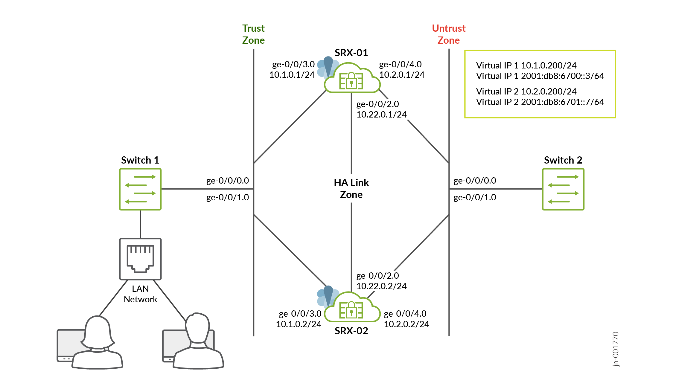
In this topology, clients in the LAN send traffic to the default gateway (the VIP). The switch forwards this traffic to both SRX Series Firewall nodes, but only the active node for that SRG (for example, SRX‑01 in the diagram) owns the VIP and processes the packets. The active node performs security checks, creates sessions, and forwards the traffic toward the untrust side. At the same time, it synchronizes session information with the backup node over the ICL link so that the peer is always ready to take over.
If the active node or its path fails, the backup node quickly takes over the VIP and vMAC. Traffic from the LAN and untrust side is then redirected to the new active node without requiring any changes on the hosts. Because sessions were already synchronized, most flows continue with minimal disruption, providing seamless failover in the network.
This example uses direct connections between the SRX Series Firewalls and switches for simplicity; in particular, the ICL in the HA Link zone is established using the ge-0/0/2.0 interface directly between devices. However, in production deployments, these links can also traverse an intermediate routed network.
Topology Overview
| Device | Interface | Zone | IP Address | Configured For |
|---|---|---|---|---|
| SRX-01 | ge-0/0/2.0 | halink | 10.22.0.1/24 | Interchassis -link (ICL) |
| ge-0/0/3.0 | trust | 10.1.0.1/24 | Connects to Switch-01 | |
| ge-0/0/4.0 | untrust | 10.2.0.1/24 | Connects to Switch-02 | |
| SRX-02 | ge-0/0/2.0 | halink | 10.22.0.2/24 | Interchassis -link (ICL) |
| ge-0/0/3.0 | trust | 10.1.0.2/24 | Connects to Switch-01 | |
| ge-0/0/4.0 | untrust | 10.2.0.2/24 | Connects to Switch-02 |
You'll perform the following tasks to build an MNHA setup:
- Configure a pair of firewalls as local and peer nodes by assigning IDs.
- Configure services redundancy groups (SRGs).
- Configure virtual IP addresses for activeness determination and enforcement. In
this example, a single virtual IP is configured with both IPv4 and IPv6
addresses using multiple
ipstatements to enable dual-stack support. - Configure a VPN profile for the high availability (ICL) traffic using IKEv2.
- Configure appropriate security policies to manage traffic in your network.
- Configure interfaces and zones according your network requirement. You must allow services such as IKE for link encryption and SSH for configuration synchronization as host inbound system services on the security zone that is associated with the ICL.
Configuration
For complete sample configurations on the DUT, see:
- Step 1: Configure Physical Interfaces
- Step 2: Configure Security Zones
- Step 3: Configure IKE Proposal for HA Link Encryption (SRX-01 and SRX-02)
- Step 4: Configure IKE Policy and Gateway (SRX-01 and SRX-02)
- Step 5: Configure IPsec Proposal and Policy (SRX-01 and SRX-02)
- Step 6: Configure IPsec VPN for HA Link Encryption (SRX-01 and SRX-02)
- Step 7: Configure Security Policy (SRX-01 and SRX-02)
- Step 8: Configure Chassis High Availability Local Identity
- Step 9: Configure Chassis High Availability Peer Identity
- Step 10: Configure Services Redundancy Group
- Step 11: Commit Configuration
Step 1: Configure Physical Interfaces
Configure the physical interfaces that will participate in the high availability setup, including the HA link, trust zone interface, and untrust zone interface.
-
SRX-01
[edit]
  user@host# set interfaces ge-0/0/2 description ha_link
  user@host# set interfaces ge-0/0/2 unit 0 family inet address 10.22.0.1/24
  user@host# set interfaces ge-0/0/3 description trust
  user@host# set interfaces ge-0/0/3 unit 0 family inet address 10.1.0.1/24
  user@host# set interfaces ge-0/0/4 description untrust
  user@host# set interfaces ge-0/0/4 unit 0 family inet address 10.2.0.1/24
- SRX-02
[edit]
  user@host# set interfaces ge-0/0/2 description ha_link
  user@host# set interfaces ge-0/0/2 unit 0 family inet address 10.22.0.2/24
  user@host# set interfaces ge-0/0/3 description trust
  user@host# set interfaces ge-0/0/3 unit 0 family inet address 10.1.0.2/24
  user@host# set interfaces ge-0/0/4 description untrust
  user@host# set interfaces ge-0/0/4 unit 0 family inet address 10.2.0.2/24
The interface configuration establishes three critical network segments for the MNHA. Interface ge-0/0/2 serves as the dedicated HA link. Interface ge-0/0/3 connects to the trust zone, handling internal network traffic. Interface ge-0/0/4 connects to the untrust zone, managing external network traffic.
Step 2: Configure Security Zones
Define security zones and assign interfaces to appropriate zones with required host-inbound traffic services and protocols.
- SRX-01
[edit]
  user@host# set security zones security-zone untrust host-inbound-traffic system-services ike
  user@host# set security zones security-zone untrust host-inbound-traffic system-services ping
  user@host# set security zones security-zone untrust host-inbound-traffic system-services ssh
  user@host# set security zones security-zone untrust host-inbound-traffic protocols bfd
  user@host# set security zones security-zone untrust host-inbound-traffic protocols bgp
  user@host# set security zones security-zone untrust interfaces ge-0/0/4.0
  user@host# set security zones security-zone trust host-inbound-traffic system-services ike
  user@host# set security zones security-zone trust host-inbound-traffic system-services ping
  user@host# set security zones security-zone trust host-inbound-traffic system-services ssh
  user@host# set security zones security-zone trust host-inbound-traffic protocols bgp
  user@host# set security zones security-zone trust host-inbound-traffic protocols bfd
  user@host# set security zones security-zone trust interfaces ge-0/0/3.0
  user@host# set security zones security-zone halink host-inbound-traffic system-services ike
  user@host# set security zones security-zone halink host-inbound-traffic system-services ping
  user@host# set security zones security-zone halink host-inbound-traffic system-services high-availability
  user@host# set security zones security-zone halink host-inbound-traffic system-services ssh
  user@host# set security zones security-zone halink host-inbound-traffic protocols bfd
  user@host# set security zones security-zone halink host-inbound-traffic protocols bgp
  user@host# set security zones security-zone halink interfaces ge-0/0/2.0
- SRX-02
[edit]
  user@host# set security zones security-zone untrust host-inbound-traffic system-services ike
  user@host# set security zones security-zone untrust host-inbound-traffic system-services ping
  user@host# set security zones security-zone untrust host-inbound-traffic system-services ssh
  user@host# set security zones security-zone untrust host-inbound-traffic protocols bfd
  user@host# set security zones security-zone untrust host-inbound-traffic protocols bgp
  user@host# set security zones security-zone untrust interfaces ge-0/0/4.0
  user@host# set security zones security-zone trust host-inbound-traffic system-services ike
  user@host# set security zones security-zone trust host-inbound-traffic system-services ping
  user@host# set security zones security-zone trust host-inbound-traffic system-services ssh
  user@host# set security zones security-zone trust host-inbound-traffic protocols bgp
  user@host# set security zones security-zone trust host-inbound-traffic protocols bfd
  user@host# set security zones security-zone trust interfaces ge-0/0/3.0
  user@host# set security zones security-zone halink host-inbound-traffic system-services ike
  user@host# set security zones security-zone halink host-inbound-traffic system-services ping
  user@host# set security zones security-zone halink host-inbound-traffic system-services high-availability
  user@host# set security zones security-zone halink host-inbound-traffic system-services ssh
  user@host# set security zones security-zone halink host-inbound-traffic protocols bfd
  user@host# set security zones security-zone halink host-inbound-traffic protocols bgp
  user@host# set security zones security-zone halink interfaces ge-0/0/2.0
Security zones segment network traffic and enforce security policies. The untrust and trust zones permit IKE, ping, SSH, and BGP/BFD services for connectivity, management, and routing, while the halink zone is dedicated to high availability.
For an MNHA setup, this configuration typically includes allowing IKE, BGP, and BFD. Always tailor the security rules to align with your network and security requirements.
Step 3: Configure IKE Proposal for HA Link Encryption (SRX-01 and SRX-02)
Create the IKE Phase 1 proposal that defines cryptographic parameters for the encrypted HA link tunnel.
[edit]
user@host# set security ike proposal MNHA_IKE_PROP description mnha_link_encr_tunnel
user@host# set security ike proposal MNHA_IKE_PROP authentication-method pre-shared-keys
user@host# set security ike proposal MNHA_IKE_PROP dh-group group14
user@host# set security ike proposal MNHA_IKE_PROP authentication-algorithm sha-256
user@host# set security ike proposal MNHA_IKE_PROP encryption-algorithm aes-256-cbc
user@host# set security ike proposal MNHA_IKE_PROP lifetime-seconds 3600
The IKE proposal defines secure HA link communication using preshared keys, DH Group 14, SHA-256, and AES-256-CBC, with a 1-hour lifetime. The settings must match on both MNHA nodes for successful IKE negotiation
Step 4: Configure IKE Policy and Gateway (SRX-01 and SRX-02)
Define the IKE policy that references the proposal and configure the IKE gateway for HA link encryption.
[edit security ike]
user@host# set security ike policy MNHA_IKE_POL description mnha_link_encr_tunnel
user@host# set security ike policy MNHA_IKE_POL proposals MNHA_IKE_PROP
user@host# set security ike policy MNHA_IKE_POL pre-shared-key ascii-text "$ABC123"
user@host# set security ike gateway MNHA_IKE_GW ike-policy MNHA_IKE_POL
user@host# set security ike gateway MNHA_IKE_GW version v2-only
The IKE policy links the cryptographic proposal with authentication credentials, while the IKE gateway uses IKEv2-only for secure and efficient tunnel establishment. This gateway is later referenced by the IPsec VPN to protect HA synchronization traffic between MNHA members.
Step 5: Configure IPsec Proposal and Policy (SRX-01 and SRX-02)
Create the IPsec Phase 2 proposal and policy that define data plane encryption parameters for the HA link tunnel.
[edit]
user@host# set security ipsec proposal MNHA_IPSEC_PROP description mnha_link_encr_tunnel
user@host# set security ipsec proposal MNHA_IPSEC_PROP protocol esp
user@host# set security ipsec proposal MNHA_IPSEC_PROP encryption-algorithm aes-256-gcm
user@host# set security ipsec proposal MNHA_IPSEC_PROP lifetime-seconds 3600
user@host# set security ipsec policy MNHA_IPSEC_POL description mnha_link_encr_tunnel
user@host# set security ipsec policy MNHA_IPSEC_POL proposals MNHA_IPSEC_PROP
The IPsec proposal secures HA traffic using ESP and AES-256-GCM for efficient encryption and integrity protection. The IPsec policy encapsulates these settings and is referenced by the VPN configuration.
Step 6: Configure IPsec VPN for HA Link Encryption (SRX-01 and SRX-02)
Create the IPsec VPN profile specifically designated for high availability link encryption.
[edit]
user@host# set security ipsec vpn IPSEC_VPN_ICL ha-link-encryption
user@host# set security ipsec vpn IPSEC_VPN_ICL ike gateway MNHA_IKE_GW
user@host# set security ipsec vpn IPSEC_VPN_ICL ike ipsec-policy MNHA_IPSEC_POL
The IPsec VPN combines the IKE gateway and IPsec policy to create an encrypted HA
tunnel. The ha-link-encryption option designates the VPN for
secure HA communication.
Step 7: Configure Security Policy (SRX-01 and SRX-02)
Establish the default security policy for traffic processing through the firewall.
[edit security policies]
user@host# set default-policy permit-all
The default permit-all policy allows traffic between zones without requiring explicit security rules. It is useful for lab or initial deployments but should be replaced with restrictive policies in production environments.
Step 8: Configure Chassis High Availability Local Identity
Define the local device's identity within the high availability setup.
- SRX-01
[edit]
  user@host# set chassis high-availability local-id 1
  user@host# set chassis high-availability local-id local-ip 10.22.0.1
- SRX-02
[edit]
  user@host# set chassis high-availability local-id 2
  user@host# set chassis high-availability local-id local-ip 10.22.0.2
The local ID and local IP uniquely identify this MNHA member. The local ID
(1) distinguishes it from its peer, while the local IP
(10.22.0.2) is used for HA communication.
Step 9: Configure Chassis High Availability Peer Identity
Define the peer device's identity and connectivity parameters within the HA.
- SRX-01
[edit]
user@host# set chassis high-availability peer-id 2 peer-ip 10.22.0.2
user@host# set chassis high-availability peer-id 2 interface ge-0/0/2.0
user@host# set chassis high-availability peer-id 2 vpn-profile IPSEC_VPN_ICL
user@host# set chassis high-availability peer-id 2 liveness-detection minimum-interval 200
user@host# set chassis high-availability peer-id 2 liveness-detection multiplier 3
- SRX-02
[edit]
user@host# set chassis high-availability peer-id 1 peer-ip 10.22.0.1
user@host# set chassis high-availability peer-id 1 interface ge-0/0/2.0
user@host# set chassis high-availability peer-id 1 vpn-profile IPSEC_VPN_ICL
user@host# set chassis high-availability peer-id 1 liveness-detection minimum-interval 200
user@host# set chassis high-availability peer-id 1 liveness-detection multiplier 3
The peer configuration identifies the remote HA member and enables secure HA communication over the dedicated HA link. Attach the IPsec VPN profile IPSEC_VPN_ICL to the peer node. You'll need this configuration to establish a secure ICL link between the nodes. Liveness detection sends heartbeats every 200 ms and declares the peer down after three missed heartbeats, allowing fast failover detection.
Step 10: Configure Services Redundancy Group
Create and configure the services redundancy group that manages virtual IPs and failover behavior.
- SRX-01
[edit]
user@host# set chassis high-availability services-redundancy-group 1 deployment-type switching
user@host# set chassis high-availability services-redundancy-group 1 peer-id 2
user@host# set chassis high-availability services-redundancy-group 1 preemption
user@host# set chassis high-availability services-redundancy-group 1 activeness-priority 200
user@host# set chassis high-availability services-redundancy-group 1 virtual-ip 1 ip 10.1.0.200/24
user@host# set chassis high-availability services-redundancy-group 1 virtual-ip 1 ip 2001:db8:6700::3/64
user@host# set chassis high-availability services-redundancy-group 1 virtual-ip 1 interface ge-0/0/3.0
user@host# set chassis high-availability services-redundancy-group 1 virtual-ip 1 use-virtual-mac
user@host# set chassis high-availability services-redundancy-group 1 virtual-ip 2 ip 10.2.0.200/24
user@host# set chassis high-availability services-redundancy-group 1 virtual-ip 2 ip 2001:db8:6701::7/64
user@host# set chassis high-availability services-redundancy-group 1 virtual-ip 2 interface ge-0/0/4.0
user@host# set chassis high-availability services-redundancy-group 1 virtual-ip 2 use-virtual-mac
user@host# set chassis high-availability services-redundancy-group 1 monitor interface ge-0/0/3
user@host# set chassis high-availability services-redundancy-group 1 monitor interface ge-0/0/4
- SRX-02
[edit]
user@host# set chassis high-availability services-redundancy-group 1 deployment-type switching
user@host# set chassis high-availability services-redundancy-group 1 peer-id 1
user@host# set chassis high-availability services-redundancy-group 1 activeness-priority 1
user@host# set chassis high-availability services-redundancy-group 1 virtual-ip 1 ip 10.1.0.200/24
user@host# set chassis high-availability services-redundancy-group 1 virtual-ip 1 ip 2001:db8:6700::3/64
user@host# set chassis high-availability services-redundancy-group 1 virtual-ip 1 interface ge-0/0/3.0
user@host# set chassis high-availability services-redundancy-group 1 virtual-ip 1 use-virtual-mac
user@host# set chassis high-availability services-redundancy-group 1 virtual-ip 2 ip 10.2.0.200/24
user@host# set chassis high-availability services-redundancy-group 1 virtual-ip 2 ip 2001:db8:6701::7/64
user@host# set chassis high-availability services-redundancy-group 1 virtual-ip 2 interface ge-0/0/4.0
user@host# set chassis high-availability services-redundancy-group 1 virtual-ip 2 use-virtual-mac
user@host# set chassis high-availability services-redundancy-group 1 monitor interface ge-0/0/3
user@host# set chassis high-availability services-redundancy-group 1 monitor interface ge-0/0/4
Note: Configuring theuse-virtual-macoption is the recommended option in most cases, except where the surrounding infrastructure would not support a moving virtual MAC address active on a port in addition to the local MAC address. - Services redundancy group enables active/passive failover in the high availability setup.
- Switching mode is used for Layer 2 adjacent HA deployments.
- Virtual IPs (VIPs) move between the HA members during failover.
- Virtual MACs (VMACs) move with VIPs, preventing ARP issues and enabling seamless failover.
- Interface monitoring tracks critical interfaces and triggers failover if they fail.
- Preemption allows a higher-priority device to regain active status after recovery.
- Activeness priority 200 ensures this device becomes the active node during MNHA startup and recovery.
Step 11: Commit Configuration
If you
are done configuring the device, enter commit from
configuration mode.
user@host# commit
warning: High Availability Mode changed, please reboot the device to avoid undesirable behavior
commit complete
Verification
| Command | Verification Task |
| show chassis high-availability information |
Validate overall High Availability (HA) status on the active and backup nodes, including whether HA is enabled, node roles, and core HA health indicators. |
| show chassis high-availability peer-info |
Confirm the peer node is reachable. |
| show chassis high-availability services-redundancy-group |
Verify redundancy group status, priorities, preempt behavior, and failover readiness. |
| show interface terse |
Verify that the virtual IP addresses are installed on the interfaces. |
| show security ipsec security-associations ha-link-encryption detail |
Confirm HA link encryption IPsec SAs are established (IKE/IPsec is up for the HA path). |
- Verify High Availability Formation and Peer Connectivity
- Verify HA Peer Communication Details and Packet Exchange
- Verify Services Redundancy Group Status and Role Assignment
- Verify IP Address Installation on Interfaces
- Verify IPsec Security Associations for HA Link Encryption
Verify High Availability Formation and Peer Connectivity
Purpose
Validate that the MNHA s properly formed with both nodes online, peer discovery is successful, and the encrypted control channel between nodes is operational. This verification confirms the foundation for all HA operations, including state synchronization and failover capability.
Action
SRX-01
user@host> show chassis high-availability information
Node failure codes:
    HW  Hardware monitoring    LB  Loopback monitoring
    MB  Mbuf monitoring        SP  SPU monitoring
    CS  Cold Sync monitoring   SU  Software Upgrade

Node Status: ONLINE
Grid-id: 0
Local-id: 1
Local-IP: 10.22.0.1
HA Peer Information:

    Peer Id: 2        IP address: 10.22.0.2     Interface: ge-0/0/2.0
    Routing Instance: default
    Encrypted: YES    Conn State: UP
    Configured BFD Detection Time: 3 * 200ms
    Cold Sync Status: COMPLETE

SRG failure event codes:
    BF  BFD monitoring
    IP  IP monitoring
    IF  Interface monitoring
    CP  Control Plane monitoring

Services Redundancy Group: 1
        Deployment Type: SWITCHING
        Status: ACTIVE
        Activeness Priority: 200
        Preemption: ENABLED
        Process Packet In Backup State: NO
        Control Plane State: READY
        System Integrity Check: N/A
        Failure Events: NONE
        Peer Information:
          Peer Id: 2
          Status : BACKUP
          Health Status: HEALTHY
          Failover Readiness: READY
SRX-02
user@host> show chassis high-availability information
Node failure codes:
    HW  Hardware monitoring    LB  Loopback monitoring
    MB  Mbuf monitoring        SP  SPU monitoring
    CS  Cold Sync monitoring   SU  Software Upgrade

Node Status: ONLINE
Grid-id: 0
Local-id: 2
Local-IP: 10.22.0.2
HA Peer Information:

    Peer Id: 1        IP address: 10.22.0.1     Interface: ge-0/0/2.0
    Routing Instance: default
    Encrypted: YES    Conn State: UP
    Configured BFD Detection Time: 3 * 200ms
    Cold Sync Status: COMPLETE

SRG failure event codes:
    BF  BFD monitoring
    IP  IP monitoring
    IF  Interface monitoring
    CP  Control Plane monitoring

Services Redundancy Group: 1
        Deployment Type: SWITCHING
        Status: BACKUP
        Activeness Priority: 1
        Preemption: DISABLED
        Process Packet In Backup State: NO
        Control Plane State: READY
        System Integrity Check: COMPLETE
        Failure Events: NONE
        Peer Information:
          Peer Id: 1
          Status : ACTIVE
          Health Status: HEALTHY
          Failover Readiness: N/A
Meaning
Node Status: ONLINEconfirms the local node is operational and participating in the HA setup.Local-id: 1andPeer Id: 2validate unique node identification required for HA membership.-
Conn State UPindicates HA link to peer (10.22.0.1 or 10.22.0.2 over ge-0/0/2.0) is established. -
Encrypted: YESconfirms IPsec encryption is protecting HA control traffic on interface. -
Deployment Type: SWITCHINGindicates a default gateway (switching) mode configuration—that is, the network has switches connected at both ends (Layer 2 network). -
Services Redundancy Group: 1showsStatus: ACTIVEorStatus: BACKUPto display current status of SRG. Cold Sync Status: COMPLETEverifies initial configuration synchronization has successfully finished, a prerequisite for SRG failover readiness.
Verify HA Peer Communication Details and Packet Exchange
Purpose
Confirm the internal secure tunnel parameters and validate bidirectional packet exchange between HA peers. This verification ensures the control plane communication infrastructure is healthy and capable of supporting state synchronization and failover messaging.
Action
SRX-01
user@host> show chassis high-availability peer-info
HA Peer Information:
Peer-ID: 2 IP address: 10.22.0.2 Interface: ge-0/0/2.0
Routing Instance: default
Encrypted: YES Conn State: UP
Cold Sync Status: COMPLETE
Internal Interface: st0.16000
Internal Local-IP: 180.100.1.1
Internal Peer-IP: 180.100.1.2
Internal Routing-instance: __juniper_private1__
Packet Statistics:
Receive Error : 0 Send Error : 0
Packet-type Sent Received
SRG Status Msg 3 5
SRG Status Ack 4 2
Attribute Msg 3 2
Attribute Ack 2 2
Pkt Req 0 0
Pkt Req Ack 0 0
SRX-02
user@host> show chassis high-availability peer-info
HA Peer Information:
Peer-ID: 1 IP address: 10.22.0.1 Interface: ge-0/0/2.0
Routing Instance: default
Encrypted: YES Conn State: UP
Cold Sync Status: COMPLETE
Internal Interface: st0.16000
Internal Local-IP: 180.100.1.2
Internal Peer-IP: 180.100.1.1
Internal Routing-instance: __juniper_private1__
Packet Statistics:
Receive Error : 0 Send Error : 0
Packet-type Sent Received
SRG Status Msg 5 2
SRG Status Ack 2 4
Attribute Msg 3 2
Attribute Ack 2 2
Pkt Req 0 0
Pkt Req Ack 0 0
Meaning
Conn State UPconfirms that the HA peer connection is established and healthy.Note: The IP range (180.100.1.x) shown in the command output serves as the ICL IPsec traffic selector. The system dynamically assigns this IP range, and it is essential not to alter or modify it. Additionally, BFD (Bidirectional Forwarding Detection) will be automatically enabled for the broader 180.x.x.x IP range.Internal Routing-instance: juniper_private1is the system-generated VRF isolating HA control traffic from user data plane- Zero
Send ErrorandReceive Errorare reported, indicating clean HA control-plane communications.
Verify Services Redundancy Group Status and Role Assignment
Purpose
Validate SRG operational states, active/backup role assignment, and failover readiness across both HA nodes. This verification confirms proper resource ownership and ensures the HA can execute failover when required.
Action
SRX-01
user@host> show chassis high-availability services-redundancy-group 1
SRG failure event codes:
BF BFD monitoring
IP IP monitoring
IF Interface monitoring
CP Control Plane monitoring
Services Redundancy Group: 1
Deployment Type: SWITCHING
Status:
                                ACTIVE
Activeness Priority: 200
Preemption: ENABLED
Process Packet In Backup State: NO
Control Plane State: READY
System Integrity Check: N/A
Failure Events: NONE
Peer Information:
Peer Id: 2
Status : BACKUP
Health Status: HEALTHY
Failover Readiness: READY
Virtual IP Info:
Index: 2
IP: 2001:db8:6701::7/64
IP2: 10.2.0.200/24
VMAC: 00:10:db:fe:01:02
Interface: ge-0/0/4.0
Status: INSTALLED
Index: 1
IP: 2001:db8:6700::3/64
IP2: 10.1.0.200/24
VMAC: 00:10:db:fe:01:01
Interface: ge-0/0/3.0
Status: INSTALLED
Split-brain Prevention Probe Info:
DST-IP: 2001:db8:6700::3
Routing Instance: default
Type: ICMP Probe
Status: NOT RUNNING
Result: N/A Reason: N/A
DST-IP: 10.1.0.200
Routing Instance: default
Type: ICMP Probe
Status: NOT RUNNING
Result: N/A Reason: N/A
Interface Monitoring:
Status: UP
IF Name: ge-0/0/4 State: Up
IF Name: ge-0/0/3 State: Up
IP SRGID Table:
SRGID IP Prefix Routing Table
1 10.2.0.200/32 default
1 2001:db8:6701::7/128 default
1 10.1.0.200/32 default
1 2001:db8:6700::3/128 default
SRX-02
user@host> show chassis high-availability services-redundancy-group 1

SRG failure event codes:
    BF  BFD monitoring
    IP  IP monitoring
    IF  Interface monitoring
    CP  Control Plane monitoring

Services Redundancy Group: 1
        Deployment Type: SWITCHING
        Status: BACKUP
        Activeness Priority: 1
        Preemption: DISABLED
        Process Packet In Backup State: NO
        Control Plane State: READY
        System Integrity Check: COMPLETE
        Failure Events: NONE
        Peer Information:
          Peer Id: 1
          Status : ACTIVE
          Health Status: HEALTHY
          Failover Readiness: N/A

        Virtual IP Info:
          Index: 2
          IP: 2001:db8:6701::7/64
          IP2: 10.2.0.200/24
          VMAC: N/A
          Interface: ge-0/0/4.0
          Status: NOT INSTALLED

          Index: 1
          IP: 2001:db8:6700::3/64
          IP2: 10.1.0.200/24
          VMAC: 00:10:db:fe:01:01
          Interface: ge-0/0/3.0
          Status: NOT INSTALLED

        Split-brain Prevention Probe Info:
          DST-IP: 2001:db8:6700::3
          Routing Instance: default
          Type: ICMP Probe
          Status: NOT RUNNING
          Result: N/A           Reason: N/A


          DST-IP: 10.1.0.200
          Routing Instance: default
          Type: ICMP Probe
          Status: NOT RUNNING
          Result: N/A           Reason: N/A


        Interface Monitoring:
      Status: UP

          IF Name: ge-0/0/4     State: Up

          IF Name: ge-0/0/3     State: Up


IP SRGID Table:
        SRGID    IP Prefix                                   Routing Table
        1        10.2.0.200/32                               default

        1        2001:db8:6701::7/128                        default

        1        10.1.0.200/32                               default

        1        2001:db8:6700::3/128                        default
Meaning
Status: ACTIVEon Node 1 andStatus: BACKUPon Node 2 confirm proper role assignment for SRG 1. This indicates peer is healthy and in ready backup state, indicating failover capability.Virtual IP Info: INSTALLEDindicates VIPs are displayed on the active node. Where as on the backup node node,Virtual IP Info: NOT INSTALLEDis displayed.VMAC: 00:10:db:fe:01:02andVMAC: 00:10:db:fe:01:01are associated with the virtual IP on the active node.Virtual IP Info: IP: 2001:db8:6701::7/64andIP2: 10.2.0.200/24confirms dual-stack support, with both IPv4 and IPv6 VIPs present.Preemption: ENABLEDon Node 1 means it will reclaim active status after recovery from failurePreemption: DISABLEDon Node 2 prevents unnecessary failovers when Node 1 returns onlineFailure Events: NONEon both nodes confirms no monitoring failures (BFD, IP, Interface, Control Plane)Health Status: HEALTHYandFailover Readiness: READYindicate the backup node can immediately assume active role if neededSystem Integrity Check: COMPLETEon backup confirms configuration and state synchronization is currentInterface Monitoring Status: UPconfirms the monitoring subsystem is actively tracking interface healthState: Upfor both monitored interfaces means no link failures are detected that would trigger SRG failover
Verify IP Address Installation on Interfaces
PurposeVerify that the virtual IP addresses are installed on the interfaces.
ActionFrom operational mode, run the following command:
SRX-01
user@host> show interfaces terse | no-more
Interface               Admin Link Proto    Local                 Remote
ge-0/0/0                up    up
gr-0/0/0                up    up
ip-0/0/0                up    up
lsq-0/0/0               up    up
lt-0/0/0                up    up
mt-0/0/0                up    up
sp-0/0/0                up    up
sp-0/0/0.0              up    up   inet
                                   inet6
sp-0/0/0.16383          up    up   inet
ge-0/0/1                up    up
ge-0/0/2                up    up
ge-0/0/2.0              up    up   inet     10.22.0.1/24
ge-0/0/3                up    up
ge-0/0/3.0              up    up   inet     10.1.0.1/24
                                            10.1.0.200/24
                                   inet6    2001:db8:6700::3/64
                                            fe80::5604:1aff:fe00:4882/64
ge-0/0/4                up    up
ge-0/0/4.0              up    up   inet     10.2.0.1/24
                                            10.2.0.200/24
                                   inet6    2001:db8:6701::7/64
                                            fe80::5604:1aff:fe00:7541/64


...
SRX-02
user@host> show interfaces terse | no-more
Interface               Admin Link Proto    Local                 Remote
ge-0/0/0                up    up
gr-0/0/0                up    up
ip-0/0/0                up    up
lsq-0/0/0               up    up
lt-0/0/0                up    up
mt-0/0/0                up    up
sp-0/0/0                up    up
sp-0/0/0.0              up    up   inet
                                   inet6
sp-0/0/0.16383          up    up   inet
ge-0/0/1                up    up
ge-0/0/2                up    up
ge-0/0/2.0              up    up   inet     10.22.0.2/24
ge-0/0/3                up    up
ge-0/0/3.0              up    up   inet     10.1.0.2/24
ge-0/0/4                up    up
ge-0/0/4.0              up    up   inet     10.2.0.2/24
dsc                     up    up

...
For brevity, the show command output is truncated to display only a few samples.
Meaning
The command output provides the following information:
- On the active node, the interface shows both dual-stack virtual IPs
10.1.0.200/16and22001:db8:6700::3/64are installed on interface ge-0/0/3.0 for VIP index 1 and10.2.0.200/16and2001:db8:6701::7/64are installed on interface ge-0/0/4.0 for VIP index 2. - On the backup node, only the local interface IP addresses are present, and the VIP is not installed.
This output ensures that only the active node handles traffic. During a failover, the VIP moves from the active node to the backup node, maintaining service continuity for both IPv4 and IPv6 traffic
Verify IPsec Security Associations for HA Link Encryption
Purpose
Validate that IPsec tunnels protecting HA control traffic are established with correct encryption parameters and are actively processing traffic. This verification ensures confidentiality and integrity of configuration synchronization and state updates between HA nodes.
Action
user@host> show security ipsec security-associations ha-link-encryption detail
ID: 495005 Virtual-system: root, VPN Name: IPSEC_VPN_ICL
  Local Gateway: 10.22.0.1, Remote Gateway: 10.22.0.2
  Traffic Selector Name: __IPSEC_VPN_ICL__ICL__2__0__multi_node__
  Local Identity: ipv4(180.100.1.1-180.100.1.1)
  Remote Identity: ipv4(180.100.1.2-180.100.1.2)
  TS Type: traffic-selector
  Version: IKEv2
  Quantum Secured: No
  Hardware Offloaded: No
  PFS group: N/A, Packet Encapsulation: None, Dest port: 0
  Passive mode tunneling: Disabled
  DF-bit: clear, Copy-Outer-DSCP: Disabled, Bind-interface: st0.16000, Policy-name: MNHA_IPSEC_POL
  Port: 500, Nego#: 0, Fail#: 0, Def-Del#: 0 Flag: 0
  HA Link Encryption Mode: Inter-Chassis-Link
  Location: FPC -, PIC -
  Anchorship: Thread -
  Distribution-Profile: default-profile
  Direction: inbound, SPI: 0x0008a5a8, AUX-SPI: 0
                              , VPN Monitoring: UP Mode: Always-Send Interval: 10secs Threshold: 10
    Hard lifetime: Expires in 3392 seconds
    Lifesize Remaining:  Unlimited
    Soft lifetime: Expires in 2774 seconds
    Mode: Tunnel(0 0), Type: dynamic, State: installed
    Protocol: ESP, Authentication: aes256-gcm, Encryption: aes-gcm (256 bits)
    Anti-replay service: counter-based enabled, Replay window size: 64
    Extended-Sequence-Number: Disabled
    tunnel-establishment: establish-tunnels-immediately
    Location: FPC 0, PIC 0
    Anchorship: Thread 0
    IKE SA Index: 16776197
  Direction: outbound, SPI: 0x00065b1f, AUX-SPI: 0
                              , VPN Monitoring: UP Mode: Always-Send Interval: 10secs Threshold: 10
    Hard lifetime: Expires in 3392 seconds
    Lifesize Remaining:  Unlimited
    Soft lifetime: Expires in 2774 seconds
    Mode: Tunnel(0 0), Type: dynamic, State: installed
    Protocol: ESP, Authentication: aes256-gcm, Encryption: aes-gcm (256 bits)
    Anti-replay service: counter-based enabled, Replay window size: 64
    Extended-Sequence-Number: Disabled
    tunnel-establishment: establish-tunnels-immediately
    Location: FPC 0, PIC 0
    Anchorship: Thread 0
    IKE SA Index: 16776197
Meaning
Local Gateway: 10.22.0.1andRemote Gateway: 10.22.0.2confirm tunnel endpoints match the HA peer addresses.HA Link Encryption Mode: Inter-Chassis-Linkconfirms this is the dedicated HA encryption tunnel.IPSEC_VPN_ICLDisplays the name of IPsec VPN profile used.CAUTION:The IP range (180.100.1.x) shown in the command output serves as the ICL IPsec traffic selector. The system dynamically assigns this IP range, and it is essential not to alter or modify it. Additionally, BFD (Bidirectional Forwarding Detection) will be automatically enabled for the broader 180.x.x.x IP range.
Appendix 1: Set Commands on All Devices
To quickly configure this example, copy the following commands, paste them into a
text file, remove any line breaks, change any details necessary to match your
network configuration. Next, copy and paste the commands into the CLI at the
[edit] hierarchy level, and then enter commit
from configuration mode.
These configurations are captured from a lab environment, and are provided for reference only. Actual configurations might vary based on the requirements of your environment.
On SRX-01
set chassis high-availability local-id 1
set chassis high-availability local-id local-ip 10.22.0.1
set chassis high-availability peer-id 2 peer-ip 10.22.0.2
set chassis high-availability peer-id 2 interface ge-0/0/2.0
set chassis high-availability peer-id 2 vpn-profile IPSEC_VPN_ICL
set chassis high-availability peer-id 2 liveness-detection minimum-interval 200
set chassis high-availability peer-id 2 liveness-detection multiplier 3
set chassis high-availability services-redundancy-group 1 deployment-type switching
set chassis high-availability services-redundancy-group 1 peer-id 2
set chassis high-availability services-redundancy-group 1 virtual-ip 1 ip 10.1.0.200/24
set chassis high-availability services-redundancy-group 1 virtual-ip 1 ip 2001:db8:6700::3/64
set chassis high-availability services-redundancy-group 1 virtual-ip 1 interface ge-0/0/3.0
set chassis high-availability services-redundancy-group 1 virtual-ip 1 use-virtual-mac
set chassis high-availability services-redundancy-group 1 virtual-ip 2 ip 10.2.0.200/24
set chassis high-availability services-redundancy-group 1 virtual-ip 2 ip 2001:db8:6701::7/64
set chassis high-availability services-redundancy-group 1 virtual-ip 2 interface ge-0/0/4.0
set chassis high-availability services-redundancy-group 1 virtual-ip 2 use-virtual-mac
set chassis high-availability services-redundancy-group 1 monitor interface ge-0/0/3
set chassis high-availability services-redundancy-group 1 monitor interface ge-0/0/4
set chassis high-availability services-redundancy-group 1 preemption
set chassis high-availability services-redundancy-group 1 activeness-priority 200
set security ike proposal MNHA_IKE_PROP description mnha_link_encr_tunnel
set security ike proposal MNHA_IKE_PROP authentication-method pre-shared-keys
set security ike proposal MNHA_IKE_PROP dh-group group14
set security ike proposal MNHA_IKE_PROP authentication-algorithm sha-256
set security ike proposal MNHA_IKE_PROP encryption-algorithm aes-256-cbc
set security ike proposal MNHA_IKE_PROP lifetime-seconds 3600
set security ike policy MNHA_IKE_POL description mnha_link_encr_tunnel
set security ike policy MNHA_IKE_POL proposals MNHA_IKE_PROP
set security ike policy MNHA_IKE_POL pre-shared-key ascii-text "$ABC123"
set security ike gateway MNHA_IKE_GW ike-policy MNHA_IKE_POL
set security ike gateway MNHA_IKE_GW version v2-only
set security ipsec proposal MNHA_IPSEC_PROP description mnha_link_encr_tunnel
set security ipsec proposal MNHA_IPSEC_PROP protocol esp
set security ipsec proposal MNHA_IPSEC_PROP encryption-algorithm aes-256-gcm
set security ipsec proposal MNHA_IPSEC_PROP lifetime-seconds 3600
set security ipsec policy MNHA_IPSEC_POL description mnha_link_encr_tunnel
set security ipsec policy MNHA_IPSEC_POL proposals MNHA_IPSEC_PROP
set security ipsec vpn IPSEC_VPN_ICL ha-link-encryption
set security ipsec vpn IPSEC_VPN_ICL ike gateway MNHA_IKE_GW
set security ipsec vpn IPSEC_VPN_ICL ike ipsec-policy MNHA_IPSEC_POL
set security zones security-zone untrust host-inbound-traffic system-services ike
set security zones security-zone untrust host-inbound-traffic system-services ping
set security zones security-zone untrust host-inbound-traffic system-services ssh
set security zones security-zone untrust host-inbound-traffic protocols bfd
set security zones security-zone untrust host-inbound-traffic protocols bgp
set security zones security-zone untrust interfaces lo0.0
set security zones security-zone untrust interfaces ge-0/0/4.0
set security zones security-zone trust host-inbound-traffic system-services ike
set security zones security-zone trust host-inbound-traffic system-services ping
set security zones security-zone trust host-inbound-traffic system-services ssh
set security zones security-zone trust host-inbound-traffic protocols bgp
set security zones security-zone trust host-inbound-traffic protocols bfd
set security zones security-zone trust interfaces ge-0/0/3.0
set security zones security-zone halink host-inbound-traffic system-services ike
set security zones security-zone halink host-inbound-traffic system-services ping
set security zones security-zone halink host-inbound-traffic system-services high-availability
set security zones security-zone halink host-inbound-traffic system-services ssh
set security zones security-zone halink host-inbound-traffic protocols bfd
set security zones security-zone halink host-inbound-traffic protocols bgp
set security zones security-zone halink interfaces ge-0/0/2.0
set security policies default-policy permit-all
set interfaces ge-0/0/2 description ha_link
set interfaces ge-0/0/2 unit 0 family inet address 10.22.0.1/24
set interfaces ge-0/0/3 description trust
set interfaces ge-0/0/3 unit 0 family inet address 10.1.0.1/24
set interfaces ge-0/0/4 description untrust
set interfaces ge-0/0/4 unit 0 family inet address 10.2.0.1/24
On SRX-02
set chassis high-availability local-id 2
set chassis high-availability local-id local-ip 10.22.0.2
set chassis high-availability peer-id 1 peer-ip 10.22.0.1
set chassis high-availability peer-id 1 interface ge-0/0/2.0
set chassis high-availability peer-id 1 vpn-profile IPSEC_VPN_ICL
set chassis high-availability peer-id 1 liveness-detection minimum-interval 200
set chassis high-availability peer-id 1 liveness-detection multiplier 3
set chassis high-availability services-redundancy-group 1 deployment-type switching
set chassis high-availability services-redundancy-group 1 peer-id 1
set chassis high-availability services-redundancy-group 1 virtual-ip 1 ip 10.1.0.200/24
set chassis high-availability services-redundancy-group 1 virtual-ip 1 ip 2001:db8:6700::3/64
set chassis high-availability services-redundancy-group 1 virtual-ip 1 interface ge-0/0/3.0
set chassis high-availability services-redundancy-group 1 virtual-ip 1 use-virtual-mac
set chassis high-availability services-redundancy-group 1 virtual-ip 2 ip 10.2.0.200/24
set chassis high-availability services-redundancy-group 1 virtual-ip 2 ip 2001:db8:6701::7/64
set chassis high-availability services-redundancy-group 1 virtual-ip 2 interface ge-0/0/4.0
set chassis high-availability services-redundancy-group 1 monitor interface ge-0/0/3
set chassis high-availability services-redundancy-group 1 monitor interface ge-0/0/4
set chassis high-availability services-redundancy-group 1 activeness-priority 1
set security ike proposal MNHA_IKE_PROP description mnha_link_encr_tunnel
set security ike proposal MNHA_IKE_PROP authentication-method pre-shared-keys
set security ike proposal MNHA_IKE_PROP dh-group group14
set security ike proposal MNHA_IKE_PROP authentication-algorithm sha-256
set security ike proposal MNHA_IKE_PROP encryption-algorithm aes-256-cbc
set security ike proposal MNHA_IKE_PROP lifetime-seconds 3600
set security ike policy MNHA_IKE_POL description mnha_link_encr_tunnel
set security ike policy MNHA_IKE_POL proposals MNHA_IKE_PROP
set security ike policy MNHA_IKE_POL pre-shared-key ascii-text "$ABC123"
set security ike gateway MNHA_IKE_GW ike-policy MNHA_IKE_POL
set security ike gateway MNHA_IKE_GW version v2-only
set security ipsec proposal MNHA_IPSEC_PROP description mnha_link_encr_tunnel
set security ipsec proposal MNHA_IPSEC_PROP protocol esp
set security ipsec proposal MNHA_IPSEC_PROP encryption-algorithm aes-256-gcm
set security ipsec proposal MNHA_IPSEC_PROP lifetime-seconds 3600
set security ipsec policy MNHA_IPSEC_POL description mnha_link_encr_tunnel
set security ipsec policy MNHA_IPSEC_POL proposals MNHA_IPSEC_PROP
set security ipsec vpn IPSEC_VPN_ICL ha-link-encryption
set security ipsec vpn IPSEC_VPN_ICL ike gateway MNHA_IKE_GW
set security ipsec vpn IPSEC_VPN_ICL ike ipsec-policy MNHA_IPSEC_POL
set security zones security-zone untrust host-inbound-traffic system-services ike
set security zones security-zone untrust host-inbound-traffic system-services ping
set security zones security-zone untrust host-inbound-traffic system-services ssh
set security zones security-zone untrust host-inbound-traffic protocols bfd
set security zones security-zone untrust host-inbound-traffic protocols bgp
set security zones security-zone untrust interfaces lo0.0
set security zones security-zone untrust interfaces ge-0/0/4.0
set security zones security-zone trust host-inbound-traffic system-services ike
set security zones security-zone trust host-inbound-traffic system-services ping
set security zones security-zone trust host-inbound-traffic system-services ssh
set security zones security-zone trust host-inbound-traffic system-services all
set security zones security-zone trust host-inbound-traffic protocols bgp
set security zones security-zone trust host-inbound-traffic protocols bfd
set security zones security-zone trust host-inbound-traffic protocols all
set security zones security-zone trust interfaces ge-0/0/3.0
set security zones security-zone halink host-inbound-traffic system-services ike
set security zones security-zone halink host-inbound-traffic system-services ping
set security zones security-zone halink host-inbound-traffic system-services high-availability
set security zones security-zone halink host-inbound-traffic system-services ssh
set security zones security-zone halink host-inbound-traffic protocols bfd
set security zones security-zone halink host-inbound-traffic protocols bgp
set security zones security-zone halink interfaces ge-0/0/2.0
set security policies default-policy permit-all
set interfaces ge-0/0/2 description ha_link
set interfaces ge-0/0/2 unit 0 family inet address 10.22.0.2/24
set interfaces ge-0/0/3 description trust
set interfaces ge-0/0/3 unit 0 family inet address 10.1.0.2/24
set interfaces ge-0/0/4 description untrust
set interfaces ge-0/0/4 unit 0 family inet address 10.2.0.2/24
The following sections show configuration snippets on the switches required for setting up MNHA setup in the network.
On Switch -01
set interfaces ge-0/0/0 description to-vsrx-1
set interfaces ge-0/0/0 mtu 9192
set interfaces ge-0/0/0 unit 0 family ethernet-switching interface-mode access
set interfaces ge-0/0/0 unit 0 family ethernet-switching vlan members lan
set interfaces ge-0/0/1 description to-vsrx-2
set interfaces ge-0/0/1 mtu 9192
set interfaces ge-0/0/1 unit 0 family ethernet-switching interface-mode access
set interfaces ge-0/0/1 unit 0 family ethernet-switching vlan members lan
set interfaces ge-0/0/2 description lan
set interfaces ge-0/0/2 mtu 9192
set interfaces ge-0/0/2 unit 0 family ethernet-switching interface-mode access
set interfaces ge-0/0/2 unit 0 family ethernet-switching vlan members lan
set vlans lan vlan-id 1001
On Switch -02
set interfaces ge-0/0/0 description to-vsrx-1
set interfaces ge-0/0/0 mtu 9192
set interfaces ge-0/0/0 unit 0 family ethernet-switching interface-mode access
set interfaces ge-0/0/0 unit 0 family ethernet-switching vlan members lan
set interfaces ge-0/0/1 description to-vsrx-2
set interfaces ge-0/0/1 mtu 9192
set interfaces ge-0/0/1 unit 0 family ethernet-switching interface-mode access
set interfaces ge-0/0/1 unit 0 family ethernet-switching vlan members lan
set vlans lan vlan-id 1001
Appendix 2: Show Configuration Output
Results (SRX-01)
From configuration mode, confirm your configuration by entering the following commands. If the output does not display the intended configuration, repeat the configuration instructions in this example to correct it.
[edit]
user@host# show chassis high-availability
local-id {
    1;
    local-ip 10.22.0.1;
}
peer-id 2 {
    peer-ip 10.22.0.2;
    interface ge-0/0/2.0;
    vpn-profile IPSEC_VPN_ICL;
    liveness-detection {
        minimum-interval 200;
        multiplier 3;
    }
}
services-redundancy-group 1 {
    deployment-type switching;
    peer-id {
        2;
    }
    virtual-ip 1 {
        ip 2001:db8:6700::3/64;
        ip 10.1.0.200/24;
        interface ge-0/0/3.0;
        use-virtual-mac;
    }
    virtual-ip 2 {
        ip 2001:db8:6701::7/64;
        ip 10.2.0.200/24;
        interface ge-0/0/4.0;
        use-virtual-mac;
    }
    monitor {
        interface {
            ge-0/0/3;
            ge-0/0/4;
        }
    }
    preemption;
    activeness-priority 200;
}
[edit]
user@host# show security ike
       proposal MNHA_IKE_PROP {
            description "mnha_link_encr_tunnel";
            authentication-method pre-shared-keys;
            dh-group group14;
            authentication-algorithm sha-256;
            encryption-algorithm aes-256-cbc;
            lifetime-seconds 3600;
        }
        policy MNHA_IKE_POL {
            description "mnha_link_encr_tunnel";
            proposals MNHA_IKE_PROP;
            pre-shared-key {
                ascii-text "$ABC123";
            }
        }
        gateway MNHA_IKE_GW {
            ike-policy MNHA_IKE_POL;
            version v2-only;
        }
    }
[edit]
user@host# show security ipsec
        proposal MNHA_IPSEC_PROP {
            description "mnha_link_encr_tunnel";
            protocol esp;
            encryption-algorithm aes-256-gcm;
            lifetime-seconds 3600;
        }
        policy MNHA_IPSEC_POL {
            description "mnha_link_encr_tunnel";
            proposals MNHA_IPSEC_PROP;
        }
        vpn IPSEC_VPN_ICL {
            ha-link-encryption;
            ike {
                gateway MNHA_IKE_GW;
                ipsec-policy MNHA_IPSEC_POL;
            }
        }
[edit]
user@host# show security zones
security-zone untrust {
    host-inbound-traffic {
        system-services {
            ike;
            ping;
            ssh;
        }
        protocols {
            bfd;
            bgp;
        }
    }
    interfaces {
        ge-0/0/4.0;
    }
}
security-zone trust {
    host-inbound-traffic {
        system-services {
            ike;
            ping;
            ssh;
        }
        protocols {
            bgp;
            bfd;
        }
    }
    interfaces {
        ge-0/0/3.0;
    }
}
security-zone halink {
    host-inbound-traffic {
        system-services {
            ike;
            ping;
            high-availability;
            ssh;
        }
        protocols {
            bfd;
            bgp;
        }
    }
    interfaces {
        ge-0/0/2.0;
    }
} [edit]
user@host# show interfaces
ge-0/0/2 {
description ha_link;
unit 0 {
family inet {
address 10.22.0.1/24;
}
}
}
ge-0/0/3 {
description trust;
unit 0 {
family inet {
address 10.1.0.1/24;
}
}
}
ge-0/0/4 {
description untrust;
unit 0 {
family inet {
address 10.2.0.1/24;
}
}
}
If you are done configuring the device, enter commit from
configuration mode.
Results (SRX-02)
From configuration mode, confirm your configuration by entering the following commands. If the output does not display the intended configuration, repeat the configuration instructions in this example to correct it.
[edit]
user@host# show chassis high-availability
local-id {
    2;
    local-ip 10.22.0.1;
}
peer-id 1 {
    peer-ip 10.22.0.2;
    interface ge-0/0/2.0;
    vpn-profile IPSEC_VPN_ICL;
    liveness-detection {
        minimum-interval 200;
        multiplier 3;
    }
}
services-redundancy-group 1 {
    deployment-type switching;
    peer-id {
        1;
    }
    virtual-ip 1 {
        ip 10.1.0.200/16;
        ip 2001:db8:6700::3/64;
        interface ge-0/0/3.0;
        use-virtual-mac;
    }
    virtual-ip 2 {
        ip 10.2.0.200/16;
        ip 2001:db8:6701::7/64;
        interface ge-0/0/4.0;
        use-virtual-mac;
    }
    monitor {
        interface {
            ge-0/0/3;
            ge-0/0/4;
        }
    }
    activeness-priority 1;
}
[edit]
user@host# show security ike
        proposal MNHA_IKE_PROP {
            description "mnha_link_encr_tunnel";
            authentication-method pre-shared-keys;
            dh-group group14;
            authentication-algorithm sha-256;
            encryption-algorithm aes-256-cbc;
            lifetime-seconds 3600;
        }
        policy MNHA_IKE_POL {
            description "mnha_link_encr_tunnel";
            proposals MNHA_IKE_PROP;
            pre-shared-key {
                ascii-text "$ABC123";
            }
        }
        gateway MNHA_IKE_GW {
            ike-policy MNHA_IKE_POL;
            version v2-only;
        }
[edit]
user@host# show security ipsec
        proposal MNHA_IPSEC_PROP {
            description "mnha_link_encr_tunnel";
            protocol esp;
            encryption-algorithm aes-256-gcm;
            lifetime-seconds 3600;
        }
        policy MNHA_IPSEC_POL {
            description "mnha_link_encr_tunnel";
            proposals MNHA_IPSEC_PROP;
        }
        vpn IPSEC_VPN_ICL {
            ha-link-encryption;
            ike {
                gateway MNHA_IKE_GW;
                ipsec-policy MNHA_IPSEC_POL;
            }
        }
[edit]
user@host# show security zones
security-zone untrust {
    host-inbound-traffic {
        system-services {
            ike;
            ping;
            ssh;
        }
        protocols {
            bfd;
            bgp;
        }
    }
    interfaces {
        ge-0/0/4.0;
    }
}
security-zone trust {
    host-inbound-traffic {
        system-services {
            ike;
            ping;
            ssh;
            all;
        }
        protocols {
            bgp;
            bfd;
            all;
        }
    }
    interfaces {
        ge-0/0/3.0;
    }
}
security-zone halink {
    host-inbound-traffic {
        system-services {
            ike;
            ping;
            high-availability;
            ssh;
        }
        protocols {
            bfd;
            bgp;
        }
    }
    interfaces {
        ge-0/0/2.0;
    }
}
[edit]
user@host# show interfaces
ge-0/0/2 {
    description ha_link;
    unit 0 {
        family inet {
            address 10.22.0.2/24;
        }
    }
}
ge-0/0/3 {
    description trust;
    unit 0 {
        family inet {
            address 10.1.0.2/24;
        }
    }
}
ge-0/0/4 {
    description untrust;
    unit 0 {
        family inet {
            address 10.2.0.2/24;
        }
    }
}