Example: Configure IPSec VPN in Active/Active Multinode High Availability on SRX Series Firewalls in a Layer 3 Network
This example shows how to configure and verify IPsec VPN for active-active Multinode High Availability setup.
Overview
Multinode High Availability supports IPsec VPN in active/active mode with multiple SRG1s (SRG1+). Each SRG still operates in active-backup mode between the two nodes, but different SRGs can be active on different nodes. This model allows multiple active IPsec tunnels to be established from both nodes simultaneously, enabling encryption and decryption on both nodes and improving bandwidth utilization.
In this example, you configure Multinode High Availability (MNHA) between two firewalls and establish high‑availability IPsec VPN tunnels from the MNHA firewall pair to a peer device. The focus is on ensuring that IPsec tunnels can be successfully established and maintained with seamless failover between the firewalls in MNHA setup.
Example Prerequisites
Software requirements |
|
Before You Begin
Benefits |
Active/active IPsec VPN in an MNHA setup improves availability and performance by allowing both nodes to simultaneously terminate and forward VPN traffic, enabling load sharing, faster convergence, and minimal traffic disruption during failures. |
Know more |
|
Learn more |
Functional Overview
Technologies used |
|
Primary verification tasks |
|
Topology Overview
Figure 1 shows the topology used in this example.
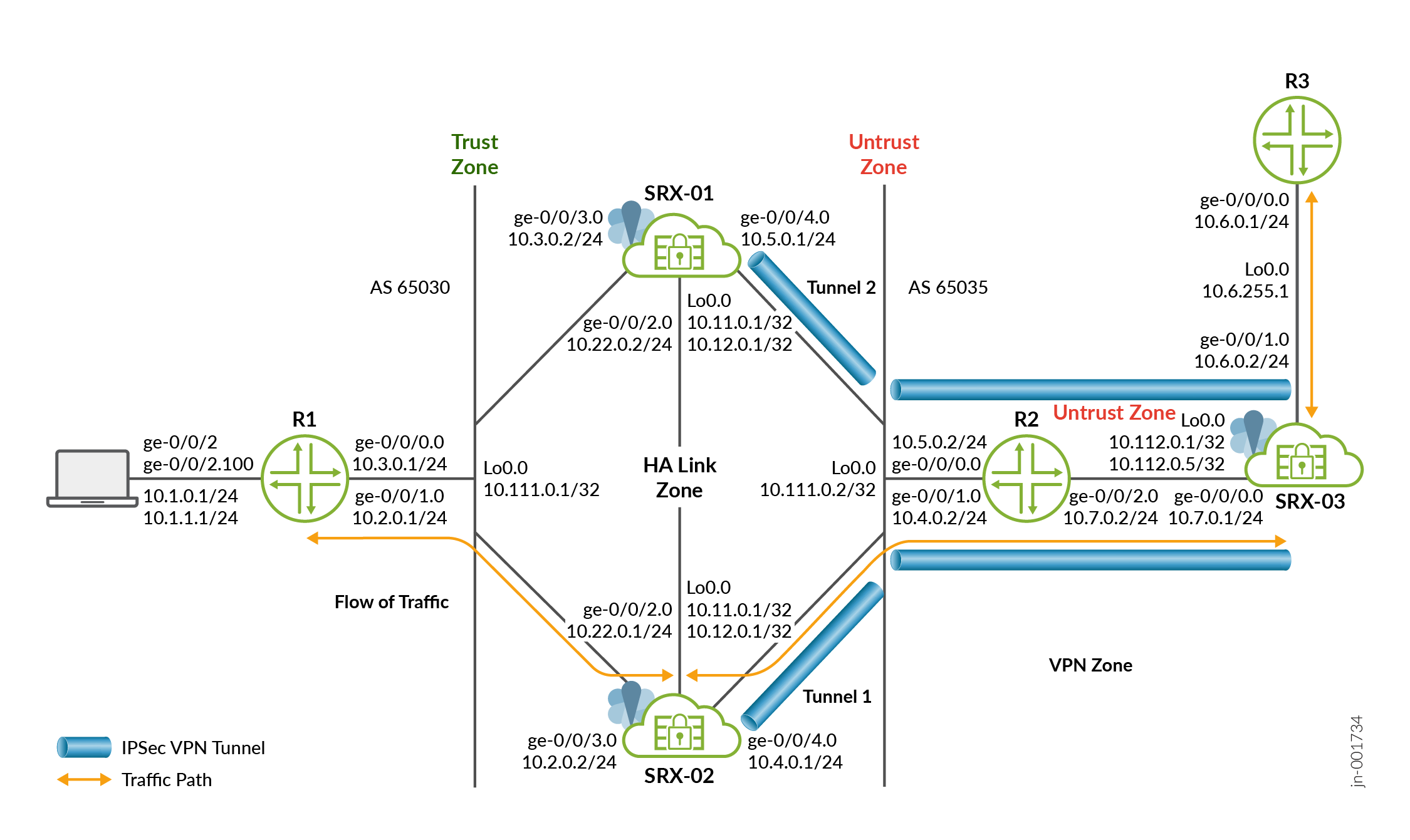
The topology demonstrates an active/active IPsec VPN deployment using Multinode High Availability (MNHA) with two firewalls forming an MNHA cluster and establishing IPsec VPN tunnels to a remote firewall (SRX-03).
The SRX-03 device acts as a peer device to the MNHA setup and it establishes individual IPsec VPN tunnels each with SRX-01 and SRX-02 devices. From the perspective of SRX‑03, the MNHA pair functions as a single logical VPN endpoint.
Traffic from the internal host flows through Router 1 → MNHA setup→ IPsec tunnels → Router 2 → SRX‑03 → Router 3. Return traffic follows the same encrypted paths. This example verifies traffic reachability from Router 3—where SRX-03 (the peer device) is connected—to Router 1, which has a remote host PC attached.
- SRX‑01 and SRX‑02 operate as an MNHA pair with multiple SRGs (SRG1+), enabling traffic to be processed actively on both nodes.
- Each SRG runs in active–backup mode internally, while the overall solution provides active‑active VPN forwarding across SRGs.
- The nodes are connected through a routed, encrypted inter‑chassis link (ICL) in the HA Link zone, using floating loopback IP addresses to synchronize control and VPN state. In this example, the link uses the ge-0/0/2.0 interface directly between devices instead of passing through an intermediate routed network.
- Trust zone interfaces connect the MNHA cluster toward the internal network through Router 1 (AS 65030).
- Untrust zone interfaces connect both SRX‑01 and SRX‑02 to Router 2 (AS 65035), which provides upstream reachability toward the remote VPN site.
- Loopback interface (lo0.0) on each SRX hosts floating IP addresses.
- SRX‑03 terminates IPsec VPN tunnels from the MNHA cluster and connects to Router 3.
- The remote SRX uses its own loopback interface as the VPN endpoint, ensuring tunnel stability independent of physical interface state.
- The VPN interfaces are placed in the VPN zone, separating encrypted traffic from untrusted transit networks.
- Multiple IPsec tunnels are established between the MNHA cluster and SRX‑03, bound to different SRGs. If a node or SRG fails, traffic is redirected to the remaining active SRG without tunnel renegotiation, as the VPN endpoints use floating IP addresses.
The following table shows the details on interfaces configuration used in this example.
| Device | Interface | Zone | IP Address | Configured For |
|---|---|---|---|---|
SRX-01 |
lo0.0 | Untrust |
10.11.0.1/32 |
Floating IP address IKE Gateway address |
10.12.0.1/32 |
IKE Gateway address |
|||
ge-0/0/2.0 |
HA Link |
10.22.0.2/24 |
Connecting ICL |
|
ge-0/0/4.0 |
Untrust |
10.5.0.1/24 |
Connects to R2 router |
|
ge-0/0/3.0 |
Trust |
10.3.0.2/24 |
Connects to R1 router |
|
SRX-02 |
lo0.0 |
Untrust |
10.12.0.1/32 |
Floating IP address IKE Gateway address |
10.11.0.1/32 |
IKE Gateway address |
|||
ge-0/0/2.0 |
HA Link |
10.22.0.1/24 |
Connecting ICL |
|
ge-0/0/3.0 |
Trust |
10.2.0.2/24 |
Connects to R1 router |
|
ge-0/0/4.0 |
Untrust |
10.4.0.1/24 |
Connects to R2 router |
|
SRX-03 |
lo0.0 | Untrust |
10.112.0.1/32 |
IKE Gateway address |
10.112.0.5/32 |
IKE Gateway address |
|||
ge-0/0/0.0 |
Untrust |
10.7.0.1/24 |
Connects to R2 router |
|
ge-0/0/1.0 |
Trust |
10.6.0.2/24 |
Connects Router |
| Device | Interface | IP Address | Configured For |
|---|---|---|---|
| Router 2 (R2) | lo0 | 10.111.0.2/32 |
Loopback interface address of R2 |
ge-0/0/1 |
10.4.0.2/24 |
Connects to |
|
ge-0/0/0 |
10.5.0.2/24 |
Connects to |
|
ge-0/0/2 |
10.7.0.2/24 |
Connects to |
|
| Router 1 (R1) | lo0 | 10.111.0.1/32 |
Loopback interface address of R1 |
ge-0/0/0 |
10.3.0.1/24 |
Connects to |
|
ge-0/0/1 |
10.2.0.1/24 |
Connects to |
|
|
|
Connects to Host network | |
| Router 3 (R3) | ge-0/0/0 |
10.6.0.1/24 |
Connects to |
| lo0 | 10.6.255.1/32 |
Loopback interface address of R3 |
Configure Firewalls
Configuration on VPN Peer Device
Configure the VPN peer device SRX‑03 with matching IPsec VPN options. Ensure IKE and IPsec parameters (peers, proposals, and policies) match those options on SRX‑01 and SRX‑02 to bring tunnels up successfully.
Verification
Use the show commands to confirm that the configuration is working properly.
| Command | Verification Task |
|---|---|
|
Display details of the MNHA status on your security device including health status of the peer node. |
show security ike security-associationsshow securiti ipsec
security-associations |
Display status about IPsec VPN connections |
- Check Multinode High Availability Setup
- Check Multinode High Availability Service Redundancy Groups
- Check IPsec VPN Status
- Testing Traffic Flow Across the VPN
- Verify Interchassis Link (ICL) Encryption Status
Check Multinode High Availability Setup
Purpose
View and verify the details of the Multinode High Availability setup configured on your security device.
Action
From operational mode, run the following command:
SRX-01
user@srx-01> show chassis high-availability information
Node failure codes:
    HW  Hardware monitoring    LB  Loopback monitoring
    MB  Mbuf monitoring        SP  SPU monitoring
    CS  Cold Sync monitoring   SU  Software Upgrade

Node Status: ONLINE
Grid-id: 0
Local-id: 2
Local-IP: 10.22.0.2
HA Peer Information:

    Peer Id: 1        IP address: 10.22.0.1     Interface: ge-0/0/2.0
    Routing Instance: default
    Encrypted: YES    Conn State: UP
    Configured BFD Detection Time: 3 * 200ms
    Cold Sync Status: COMPLETE

SRG failure event codes:
    BF  BFD monitoring
    IP  IP monitoring
    IF  Interface monitoring
    CP  Control Plane monitoring

Services Redundancy Group: 1
        Deployment Type: ROUTING
        Status: BACKUP
        Activeness Priority: 200
        Preemption: ENABLED
        Process Packet In Backup State: NO
        Control Plane State: READY
        System Integrity Check: COMPLETE
        Failure Events: NONE
        Peer Information:
          Peer Id: 1
          Status : ACTIVE
          Health Status: HEALTHY
          Failover Readiness: N/A


Services Redundancy Group: 2
        Deployment Type: ROUTING
        Status: ACTIVE
        Activeness Priority: 1
        Preemption: DISABLED
        Process Packet In Backup State: NO
        Control Plane State: READY
        System Integrity Check: N/A
        Failure Events: NONE
        Peer Information:
          Peer Id: 1
          Status : BACKUP
          Health Status: HEALTHY
          Failover Readiness: READY
SRX-02
user@srx-02> show chassis high-availability information
Node failure codes:
    HW  Hardware monitoring    LB  Loopback monitoring
    MB  Mbuf monitoring        SP  SPU monitoring
    CS  Cold Sync monitoring   SU  Software Upgrade

Node Status: ONLINE
Grid-id: 0
Local-id: 1
Local-IP: 10.22.0.1
HA Peer Information:

    Peer Id: 2        IP address: 10.22.0.2     Interface: ge-0/0/2.0
    Routing Instance: default
    Encrypted: YES    Conn State: UP
    Configured BFD Detection Time: 3 * 200ms
    Cold Sync Status: COMPLETE

SRG failure event codes:
    BF  BFD monitoring
    IP  IP monitoring
    IF  Interface monitoring
    CP  Control Plane monitoring

Services Redundancy Group: 1
        Deployment Type: ROUTING
        Status: ACTIVE
        Activeness Priority: 1
        Preemption: DISABLED
        Process Packet In Backup State: NO
        Control Plane State: READY
        System Integrity Check: N/A
        Failure Events: NONE
        Peer Information:
          Peer Id: 2
          Status : BACKUP
          Health Status: HEALTHY
          Failover Readiness: NOT READY


Services Redundancy Group: 2
        Deployment Type: ROUTING
        Status: BACKUP
        Activeness Priority: 200
        Preemption: DISABLED
        Process Packet In Backup State: NO
        Control Plane State: READY
        System Integrity Check: COMPLETE
        Failure Events: NONE
        Peer Information:
          Peer Id: 2
          Status : ACTIVE
          Health Status: HEALTHY
          Failover Readiness: N/A
Meaning
Verify these details from the command output:
Local node and peer node details such as IP address and ID.
The field
Encrypted: YESindicates that the traffic is protected.The field
Deployment Type: ROUTINGindicates a Layer 3 mode configuration—that is, the network has routers on both sides.The field
Services Redundancy Group: 1andServices Redundancy Group: 2indicate the status of the SRG1 and SRG2 (active or backup) on that node.
Check Multinode High Availability Service Redundancy Groups
Purpose
Verify that the SRGs are configured and working correctly.
Action
From operational mode, run the following command:
user@srx-01> show chassis high-availability services-redundancy-group 1
SRG failure event codes:
    BF  BFD monitoring
    IP  IP monitoring
    IF  Interface monitoring
    CP  Control Plane monitoring

Services Redundancy Group: 1
        Deployment Type: ROUTING
        Status: BACKUP
        Activeness Priority: 200
        Preemption: ENABLED
        Process Packet In Backup State: NO
        Control Plane State: READY
        System Integrity Check: COMPLETE
        Failure Events: NONE
        Peer Information:
          Peer Id: 1
          Status : ACTIVE
          Health Status: HEALTHY
          Failover Readiness: N/A

        Signal Route Info:
          Active Signal Route:
          IP: 10.39.1.1
          Routing Instance: default
          Status: NOT INSTALLED

          Backup Signal Route:
          IP: 10.39.1.2
          Routing Instance: default
          Status: INSTALLED

        Split-brain Prevention Probe Info:
          DST-IP: 10.111.0.1
          SRC-IP: 10.3.0.2
          Routing Instance: default
          Type: ICMP Probe
          Status: NOT RUNNING
          Result: N/A           Reason: N/A


        BFD Monitoring:
      Status: UNKNOWN

          SRC-IP: 10.5.0.1     DST-IP: 10.5.0.2
          Routing Instance: default
          Type: SINGLE-HOP
          IFL Name: ge-0/0/3.0
          State: INSTALLED


        Interface Monitoring:
      Status: UP

          IF Name: ge-0/0/4     State: Up

          IF Name: ge-0/0/3     State: Up


IP SRGID Table:
        SRGID    IP Prefix                                   Routing Table
        1        10.11.0.0/24                                default
user@srx-01> show chassis high-availability services-redundancy-group 2
SRG failure event codes:
    BF  BFD monitoring
    IP  IP monitoring
    IF  Interface monitoring
    CP  Control Plane monitoring

Services Redundancy Group: 2
        Deployment Type: ROUTING
        Status: ACTIVE
        Activeness Priority: 1
        Preemption: DISABLED
        Process Packet In Backup State: NO
        Control Plane State: READY
        System Integrity Check: N/A
        Failure Events: NONE
        Peer Information:
          Peer Id: 1
          Status : BACKUP
          Health Status: HEALTHY
          Failover Readiness: READY

        Signal Route Info:
          Active Signal Route:
          IP: 10.49.1.1
          Routing Instance: default
          Status: INSTALLED

          Backup Signal Route:
          IP: 10.49.1.2
          Routing Instance: default
          Status: NOT INSTALLED

        Split-brain Prevention Probe Info:
          DST-IP: 10.111.0.1
          SRC-IP: 10.12.0.1
          Routing Instance: default
          Type: ICMP Probe
          Status: NOT RUNNING
          Result: N/A           Reason: N/A


        BFD Monitoring:
      Status: UNKNOWN

          SRC-IP: 10.5.0.1     DST-IP: 10.5.0.2
          Routing Instance: default
          Type: SINGLE-HOP
          IFL Name: ge-0/0/3.0
          State: INSTALLED


        Interface Monitoring:
      Status: UP

          IF Name: ge-0/0/4     State: Up

          IF Name: ge-0/0/3     State: Up


IP SRGID Table:
        SRGID    IP Prefix                                   Routing Table
        2        10.12.0.0/24                                default
Meaning
Verify these details from the command output:
Peer node details such as deployment type, status, active and back up signal routes.
Split-brain preventions probe, IP monitoring and BFD monitoring status.
Associated IP prefix table.
Check IPsec VPN Status
Purpose
Confirm VPN status by checking the status of any IKE security associations at SRG level.
Action
Run the following commands on SRX-01, SRX-02, and SRX-03 (VPN peer device):
SRX-01
user@srx-01> show security ike security-associations
Index   State  Initiator cookie  Responder cookie  Mode           Remote Address
16777489 UP    1fef3ef467ee0439  8c2139689c37cbc8  IKEv2          10.112.0.1
33554706 UP    a3eb35ebcb216367  2ad794a8e09152c4  IKEv2          10.112.0.5
user@srx-01> show security ike security-associations srg-id 1
Index   State  Initiator cookie  Responder cookie  Mode           Remote Address
16777489 UP    1fef3ef467ee0439  8c2139689c37cbc8  IKEv2          10.112.0.1
16777491 UP    81dc38812e7869d0  f6c9b8cddd8228a6  IKEv2          10.112.0.1
user@srx-01> show security ike security-associations srg-id 2
Index   State  Initiator cookie  Responder cookie  Mode           Remote Address
33554706 UP    a3eb35ebcb216367  2ad794a8e09152c4  IKEv2          10.112.0.5
user@srx-01> show security ipsec security-associations
  Total active tunnels: 2     Total IPsec sas: 2
  ID      Algorithm       SPI      Life:sec/kb  Mon lsys Port  Gateway
  <17277217 ESP:aes-cbc-256/sha256 0x27ea1472 1225/ unlim - root 500 10.112.0.1
  >17277217 ESP:aes-cbc-256/sha256 0x4f257994 1225/ unlim - root 500 10.112.0.1
  <34054492 ESP:aes-cbc-256/sha256 0x5b93d8cb 1078/ unlim - root 500 10.112.0.5
  >34054492 ESP:aes-cbc-256/sha256 0x7c1356b8 1078/ unlim - root 500 10.112.0.5
user@srx-01> show security ipsec statistics
  ESP Statistics:
  Encrypted bytes:             5772
  Decrypted bytes:             2604
  Encrypted packets:             37
  Decrypted packets:             31
AH Statistics:
  Input bytes:                    0
  Output bytes:                   0
  Input packets:                  0
  Output packets:                 0
Errors:
  AH authentication failures: 0, Replay errors: 0
  ESP authentication failures: 0, ESP decryption failures: 0
  Bad headers: 0, Bad trailers: 0
  Invalid SPI: 0, TS check fail: 0
  Exceeds tunnel MTU: 0
  Discarded: 0
SRX-02
user@srx-02> show security ike security-associations
Index   State  Initiator cookie  Responder cookie  Mode           Remote Address
16777503 UP    ed0571780c0e05a7  9d760fc5677e5072  IKEv2          10.112.0.1
33554720 UP    8b6ca20b53f20e90  4249b4b9afe23888  IKEv2          10.112.0.5
user@srx-02> show security ike security-associations srg-id 1
Index   State  Initiator cookie  Responder cookie  Mode           Remote Address
16777503 UP    ed0571780c0e05a7  9d760fc5677e5072  IKEv2          10.112.0.1
user@srx-02> show security ike security-associations srg-id 2
Index   State  Initiator cookie  Responder cookie  Mode           Remote Address
33554720 UP    8b6ca20b53f20e90  4249b4b9afe23888  IKEv2          10.112.0.5
user@srx-01> show security ipsec security-associations
    Total active tunnels: 2     Total IPsec sas: 2
  ID      Algorithm       SPI      Life:sec/kb  Mon lsys Port  Gateway
  <17277217 ESP:aes-cbc-256/sha256 0xba7f1385 1524/ unlim - root 500 10.112.0.1
  >17277217 ESP:aes-cbc-256/sha256 0x8dd71e97 1524/ unlim - root 500 10.112.0.1
  <34054492 ESP:aes-cbc-256/sha256 0xb9de9d4b 1136/ unlim - root 500 10.112.0.5
  >34054492 ESP:aes-cbc-256/sha256 0x5daab807 1136/ unlim - root 500 10.112.0.5
SRX-03
user@srx-03> show security ike security-associations
Index   State  Initiator cookie  Responder cookie  Mode           Remote Address
305     UP     ed0571780c0e05a7  9d760fc5677e5072  IKEv2          10.11.0.1
306     UP     8b6ca20b53f20e90  4249b4b9afe23888  IKEv2          10.12.0.1
user@srx-03> show security ipsec security-associations
  Total active tunnels: 2     Total IPsec sas: 2
  ID      Algorithm       SPI      Life:sec/kb  Mon lsys Port  Gateway
  <500064 ESP:aes-cbc-256/sha256 0x5daab807 1014/ unlim - root 500 10.12.0.1
  >500064 ESP:aes-cbc-256/sha256 0xb9de9d4b 1014/ unlim - root 500 10.12.0.1
  <500063 ESP:aes-cbc-256/sha256 0x8dd71e97 1402/ unlim - root 500 10.11.0.1
  >500063 ESP:aes-cbc-256/sha256 0xba7f1385 1402/ unlim - root 500 10.11.0.1
user@srx-03> show security ipsec statistics
 ESP Statistics:
  Encrypted bytes:             5928
  Decrypted bytes:             3192
  Encrypted packets:             38
  Decrypted packets:             38
AH Statistics:
  Input bytes:                    0
  Output bytes:                   0
  Input packets:                  0
  Output packets:                 0
Errors:
  AH authentication failures: 0, Replay errors: 0
  ESP authentication failures: 0, ESP decryption failures: 0
  Bad headers: 0, Bad trailers: 0
  Invalid SPI: 0, TS check fail: 0
  Exceeds tunnel MTU: 0
  Discarded: 0
Meaning
Verify these details from the command output:
- IP addresses of the remote peers.
- The state showing UP for both remote peers indicates the successful association of Phase 1 and Phase 2 establishment.
- The remote peer IP address, IKE policy, and external interfaces are all correct.
- The IPsec tunnels are up, actively passing traffic, and operating without errors
Testing Traffic Flow Across the VPN
Purpose
Verify the traffic flow across the VPN.
Action
Use the ping command from Router 3, which is connected to the peer VPN firewall (SRX-03), to test traffic flow to Router 1, where the host is connected.
From operational mode, enter the ping command.
user@router-03> ping 10.1.0.1 source 10.6.0.1 count 2
PING 10.1.0.1 (10.1.0.1): 56 data bytes
64 bytes from 10.1.0.1: icmp_seq=0 ttl=62 time=16.757 ms
64 bytes from 10.1.0.1: icmp_seq=1 ttl=62 time=4.536 ms

--- 10.1.0.1 ping statistics ---
2 packets transmitted, 2 packets received, 0% packet loss
round-trip min/avg/max/stddev = 4.536/10.646/16.757/6.111 ms
user@router-03> ping 10.1.1.1 source 10.6.255.1 count 2
PING 10.1.1.1 (10.1.1.1): 56 data bytes
64 bytes from 10.1.1.1: icmp_seq=0 ttl=62 time=4.747 ms
64 bytes from 10.1.1.1: icmp_seq=1 ttl=62 time=4.876 ms

--- 10.1.1.1 ping statistics ---
2 packets transmitted, 2 packets received, 0% packet loss
round-trip min/avg/max/stddev = 4.747/4.812/4.876/0.064 ms
Meaning
This ping output confirms successful end‑to‑end connectivity across the IPsec VPN between the remote site and the internal network.
If the ping command fails, there might be a problem with the routing, security policies, end host, or encryption and decryption of ESP packets
Verify Interchassis Link (ICL) Encryption Status
Purpose
Verify the interchassis link (ICL) status.
Action
Run the following command on SRX-01:
user@srx-01> show security ipsec security-associations ha-link-encryption detail
ID: 495005 Virtual-system: root, VPN Name: L3HA_IPSEC_VPN
  Local Gateway: 10.22.0.2, Remote Gateway: 10.22.0.1
  Traffic Selector Name: __L3HA_IPSEC_VPN__ICL__1__0__multi_node__
  Local Identity: ipv4(180.100.1.2-180.100.1.2)
  Remote Identity: ipv4(180.100.1.1-180.100.1.1)
  TS Type: traffic-selector
  Version: IKEv2
  Quantum Secured: No
  Hardware Offloaded: No
  PFS group: N/A, Packet Encapsulation: None, Dest port: 0
  Passive mode tunneling: Disabled
  DF-bit: clear, Copy-Outer-DSCP: Disabled, Bind-interface: st0.16000, Policy-name: L3HA_IPSEC_POL
  Port: 500, Nego#: 0, Fail#: 0, Def-Del#: 0 Flag: 0
  HA Link Encryption Mode: Inter-Chassis-Link
  Location: FPC -, PIC -
  Anchorship: Thread -
  Distribution-Profile: default-profile
  Direction: inbound, SPI: 0x000a3f8b, AUX-SPI: 0
                              , VPN Monitoring: UP Mode: Always-Send Interval: 10secs Threshold: 10
    Hard lifetime: Expires in 288 seconds
    Lifesize Remaining:  Unlimited
    Soft lifetime: Expires in 220 seconds
    Mode: Tunnel(0 0), Type: dynamic, State: installed
    Protocol: ESP, Authentication: aes256-gcm, Encryption: aes-gcm (256 bits)
    Anti-replay service: counter-based enabled, Replay window size: 64
    Extended-Sequence-Number: Disabled
    tunnel-establishment: establish-tunnels-immediately
    Location: FPC 0, PIC 0
    Anchorship: Thread 0
    IKE SA Index: 16777052
  Direction: outbound, SPI: 0x000449f7, AUX-SPI: 0
                              , VPN Monitoring: UP Mode: Always-Send Interval: 10secs Threshold: 10
    Hard lifetime: Expires in 288 seconds
    Lifesize Remaining:  Unlimited
    Soft lifetime: Expires in 220 seconds
    Mode: Tunnel(0 0), Type: dynamic, State: installed
    Protocol: ESP, Authentication: aes256-gcm, Encryption: aes-gcm (256 bits)
    Anti-replay service: counter-based enabled, Replay window size: 64
    Extended-Sequence-Number: Disabled
    tunnel-establishment: establish-tunnels-immediately
    Location: FPC 0, PIC 0
    Anchorship: Thread 0
    IKE SA Index: 16777052
Meaning
The command output provides IPsec SAs used to encrypt the MNHA ICL link. It protects control, routing, and state synchronization traffic between SRX‑01 and SRX‑02
The IP range (180.100.1.x) shown in the command output serves as the ICL IPsec traffic selector. The system dynamically assigns this IP range, and it is essential not to alter or modify it. Additionally, BFD (Bidirectional Forwarding Detection) will be automatically enabled for the broader 180.x.x.x IP range.
Set Commands on all Devices
- vSRX Virtual Firewall (SRX-01)
- vSRX Virtual Firewall (SRX-02)
- vSRX Virtual Firewall (SRX-03)
- Router 1
- Router 2
- Router 3
vSRX Virtual Firewall (SRX-01)
set chassis high-availability local-id 2
set chassis high-availability local-id local-ip 10.22.0.2
set chassis high-availability peer-id 1 peer-ip 10.22.0.1
set chassis high-availability peer-id 1 interface ge-0/0/2.0
set chassis high-availability peer-id 1 vpn-profile L3HA_IPSEC_VPN
set chassis high-availability peer-id 1 liveness-detection minimum-interval 200
set chassis high-availability peer-id 1 liveness-detection multiplier 3
set chassis high-availability services-redundancy-group 1 deployment-type routing
set chassis high-availability services-redundancy-group 1 peer-id 1
set chassis high-availability services-redundancy-group 1 activeness-probe dest-ip 10.111.0.1
set chassis high-availability services-redundancy-group 1 activeness-probe dest-ip src-ip 10.3.0.2
set chassis high-availability services-redundancy-group 1 monitor bfd-liveliness 10.5.0.2 src-ip 10.5.0.1
set chassis high-availability services-redundancy-group 1 monitor bfd-liveliness 10.5.0.2 session-type singlehop
set chassis high-availability services-redundancy-group 1 monitor bfd-liveliness 10.5.0.2 interface ge-0/0/3.0
set chassis high-availability services-redundancy-group 1 monitor interface ge-0/0/3
set chassis high-availability services-redundancy-group 1 monitor interface ge-0/0/4
set chassis high-availability services-redundancy-group 1 active-signal-route 10.39.1.1
set chassis high-availability services-redundancy-group 1 backup-signal-route 10.39.1.2
set chassis high-availability services-redundancy-group 1 prefix-list SRG1_PFX
set chassis high-availability services-redundancy-group 1 managed-services ipsec
set chassis high-availability services-redundancy-group 1 preemption
set chassis high-availability services-redundancy-group 1 activeness-priority 200
set chassis high-availability services-redundancy-group 2 peer-id 1
set chassis high-availability services-redundancy-group 2 activeness-probe dest-ip 10.111.0.1
set chassis high-availability services-redundancy-group 2 activeness-probe dest-ip src-ip 10.12.0.1
set chassis high-availability services-redundancy-group 2 monitor bfd-liveliness 10.5.0.2 src-ip 10.5.0.1
set chassis high-availability services-redundancy-group 2 monitor bfd-liveliness 10.5.0.2 session-type singlehop
set chassis high-availability services-redundancy-group 2 monitor bfd-liveliness 10.5.0.2 interface ge-0/0/3.0
set chassis high-availability services-redundancy-group 2 monitor interface ge-0/0/3
set chassis high-availability services-redundancy-group 2 monitor interface ge-0/0/4
set chassis high-availability services-redundancy-group 2 active-signal-route 10.49.1.1
set chassis high-availability services-redundancy-group 2 backup-signal-route 10.49.1.2
set chassis high-availability services-redundancy-group 2 prefix-list SRG2_PFX
set chassis high-availability services-redundancy-group 2 managed-services ipsec
set chassis high-availability services-redundancy-group 2 activeness-priority 1
set security ike proposal L3HA_IKE_PROP description l3ha_link_encr_tunnel
set security ike proposal L3HA_IKE_PROP authentication-method pre-shared-keys
set security ike proposal L3HA_IKE_PROP dh-group group14
set security ike proposal L3HA_IKE_PROP authentication-algorithm sha-256
set security ike proposal L3HA_IKE_PROP encryption-algorithm aes-256-cbc
set security ike proposal L3HA_IKE_PROP lifetime-seconds 300
set security ike proposal SRG1_IKE_PROP authentication-method pre-shared-keys
set security ike proposal SRG1_IKE_PROP dh-group group14
set security ike proposal SRG1_IKE_PROP authentication-algorithm sha-256
set security ike proposal SRG1_IKE_PROP encryption-algorithm aes-256-cbc
set security ike proposal SRG1_IKE_PROP lifetime-seconds 3600
set security ike proposal SRG2_IKE_PROP authentication-method pre-shared-keys
set security ike proposal SRG2_IKE_PROP dh-group group14
set security ike proposal SRG2_IKE_PROP authentication-algorithm sha-256
set security ike proposal SRG2_IKE_PROP encryption-algorithm aes-256-cbc
set security ike proposal SRG2_IKE_PROP lifetime-seconds 3600
set security ike policy L3HA_IKE_POL description l3ha_link_encr_tunnel
set security ike policy L3HA_IKE_POL proposals L3HA_IKE_PROP
set security ike policy L3HA_IKE_POL pre-shared-key ascii-text "$abc123"
set security ike policy SRG1_IKE_POL1 proposals SRG1_IKE_PROP
set security ike policy SRG1_IKE_POL1 pre-shared-key ascii-text "$abc123"
set security ike policy SRG2_IKE_POL500 proposals SRG2_IKE_PROP
set security ike policy SRG2_IKE_POL500 pre-shared-key ascii-text "$abc123"
set security ike gateway L3HA_IKE_GW ike-policy L3HA_IKE_POL
set security ike gateway L3HA_IKE_GW version v2-only
set security ike gateway SRG1_IKE_GW1 ike-policy SRG1_IKE_POL1
set security ike gateway SRG1_IKE_GW1 address 10.112.0.1
set security ike gateway SRG1_IKE_GW1 external-interface lo0
set security ike gateway SRG1_IKE_GW1 local-address 10.11.0.1
set security ike gateway SRG1_IKE_GW1 version v2-only
set security ike gateway SRG2_IKE_GW500 ike-policy SRG2_IKE_POL500
set security ike gateway SRG2_IKE_GW500 address 10.112.0.5
set security ike gateway SRG2_IKE_GW500 external-interface lo0
set security ike gateway SRG2_IKE_GW500 local-address 10.12.0.1
set security ike gateway SRG2_IKE_GW500 version v2-only
set security ipsec proposal L3HA_IPSEC_PROP description l3ha_link_encr_tunnel
set security ipsec proposal L3HA_IPSEC_PROP protocol esp
set security ipsec proposal L3HA_IPSEC_PROP encryption-algorithm aes-256-gcm
set security ipsec proposal L3HA_IPSEC_PROP lifetime-seconds 300
set security ipsec proposal SRG1_IPSEC_PROP protocol esp
set security ipsec proposal SRG1_IPSEC_PROP authentication-algorithm hmac-sha-256-128
set security ipsec proposal SRG1_IPSEC_PROP encryption-algorithm aes-256-cbc
set security ipsec proposal SRG1_IPSEC_PROP lifetime-seconds 1800
set security ipsec proposal SRG2_IPSEC_PROP protocol esp
set security ipsec proposal SRG2_IPSEC_PROP authentication-algorithm hmac-sha-256-128
set security ipsec proposal SRG2_IPSEC_PROP encryption-algorithm aes-256-cbc
set security ipsec proposal SRG2_IPSEC_PROP lifetime-seconds 1800
set security ipsec policy L3HA_IPSEC_POL description l3ha_link_encr_tunnel
set security ipsec policy L3HA_IPSEC_POL proposals L3HA_IPSEC_PROP
set security ipsec policy SRG1_IPSEC_POL1 proposals SRG1_IPSEC_PROP
set security ipsec policy SRG2_IPSEC_POL501 proposals SRG2_IPSEC_PROP
set security ipsec policy SRG2_IPSEC_POL500 proposals SRG2_IPSEC_PROP
set security ipsec policy SRG2_IPSEC_POL502 proposals SRG2_IPSEC_PROP
set security ipsec policy SRG2_IPSEC_POL503 proposals SRG2_IPSEC_PROP
set security ipsec vpn L3HA_IPSEC_VPN ha-link-encryption
set security ipsec vpn L3HA_IPSEC_VPN ike gateway L3HA_IKE_GW
set security ipsec vpn L3HA_IPSEC_VPN ike ipsec-policy L3HA_IPSEC_POL
set security ipsec vpn SRG1_IPSEC_VPN1 bind-interface st0.1
set security ipsec vpn SRG1_IPSEC_VPN1 ike gateway SRG1_IKE_GW1
set security ipsec vpn SRG1_IPSEC_VPN1 ike ipsec-policy SRG1_IPSEC_POL1
set security ipsec vpn SRG1_IPSEC_VPN1 establish-tunnels on-traffic
set security ipsec vpn SRG2_IPSEC_VPN500 bind-interface st0.500
set security ipsec vpn SRG2_IPSEC_VPN500 ike gateway SRG2_IKE_GW500
set security ipsec vpn SRG2_IPSEC_VPN500 ike ipsec-policy SRG2_IPSEC_POL500
set security ipsec vpn SRG2_IPSEC_VPN500 traffic-selector ts500 local-ip 10.1.1.1/32
set security ipsec vpn SRG2_IPSEC_VPN500 traffic-selector ts500 remote-ip 10.6.255.1/32
set security ipsec vpn SRG2_IPSEC_VPN500 establish-tunnels on-traffic
set security zones security-zone vpn host-inbound-traffic system-services ping
set security zones security-zone vpn host-inbound-traffic protocols bgp
set security zones security-zone vpn host-inbound-traffic protocols bfd
set security zones security-zone vpn interfaces st0.1
set security zones security-zone vpn interfaces st0.500
set security zones security-zone untrust host-inbound-traffic system-services ike
set security zones security-zone untrust host-inbound-traffic system-services ping
set security zones security-zone untrust host-inbound-traffic system-services ssh
set security zones security-zone untrust host-inbound-traffic protocols bfd
set security zones security-zone untrust host-inbound-traffic protocols bgp
set security zones security-zone untrust interfaces lo0.0
set security zones security-zone untrust interfaces ge-0/0/4.0
set security zones security-zone trust host-inbound-traffic system-services ike
set security zones security-zone trust host-inbound-traffic system-services ping
set security zones security-zone trust host-inbound-traffic system-services ssh
set security zones security-zone trust host-inbound-traffic protocols all
set security zones security-zone trust host-inbound-traffic protocols bgp
set security zones security-zone trust host-inbound-traffic protocols bfd
set security zones security-zone trust interfaces ge-0/0/3.0
set security zones security-zone halink host-inbound-traffic system-services ike
set security zones security-zone halink host-inbound-traffic system-services ping
set security zones security-zone halink host-inbound-traffic system-services high-availability
set security zones security-zone halink host-inbound-traffic system-services ssh
set security zones security-zone halink host-inbound-traffic protocols bfd
set security zones security-zone halink host-inbound-traffic protocols bgp
set security zones security-zone halink interfaces ge-0/0/2.0
set security policies default-policy permit-all
set interfaces ge-0/0/1 unit 0 family inet
set interfaces ge-0/0/2 description ha_link
set interfaces ge-0/0/2 unit 0 family inet address 10.22.0.2/24
set interfaces ge-0/0/3 description trust
set interfaces ge-0/0/3 unit 0 family inet address 10.3.0.2/24
set interfaces ge-0/0/4 description route2
set interfaces ge-0/0/4 unit 0 family inet address 10.5.0.1/24
set interfaces lo0 description untrust
set interfaces lo0 unit 0 family inet address 10.11.0.1/32
set interfaces lo0 unit 0 family inet address 10.12.0.1/32
set interfaces st0 unit 1 family inet
set interfaces st0 unit 1 family inet6
set interfaces st0 unit 500 family inet
set interfaces st0 unit 500 family inet6
set policy-options prefix-list SRG1_PFX 10.11.0.0/24
set policy-options prefix-list SRG2_PFX 10.12.0.0/24
set policy-options route-filter-list srg1_rf_list 10.11.0.0/24 orlonger
set policy-options route-filter-list srg1_rf_list 10.1.0.0/24 orlonger
set policy-options route-filter-list srg1_rf_list 10.6.0.0/24 orlonger
set policy-options route-filter-list srg2_rf_list 10.12.0.0/24 orlonger
set policy-options route-filter-list srg2_rf_list 10.1.1.0/24 orlonger
set policy-options route-filter-list srg2_rf_list 10.6.255.0/24 orlonger
set policy-options policy-statement ipsec_pol term 1 from route-filter-list srg1_rf_list
set policy-options policy-statement ipsec_pol term 1 from condition active_route_exists_srg1
set policy-options policy-statement ipsec_pol term 1 then metric 10
set policy-options policy-statement ipsec_pol term 1 then accept
set policy-options policy-statement ipsec_pol term 2 from route-filter-list srg1_rf_list
set policy-options policy-statement ipsec_pol term 2 from condition backup_route_exists_srg1
set policy-options policy-statement ipsec_pol term 2 then metric 20
set policy-options policy-statement ipsec_pol term 2 then accept
set policy-options policy-statement ipsec_pol term 3 from route-filter-list srg2_rf_list
set policy-options policy-statement ipsec_pol term 3 from condition active_route_exists_srg2
set policy-options policy-statement ipsec_pol term 3 then metric 10
set policy-options policy-statement ipsec_pol term 3 then accept
set policy-options policy-statement ipsec_pol term 4 from route-filter-list srg2_rf_list
set policy-options policy-statement ipsec_pol term 4 from condition backup_route_exists_srg2
set policy-options policy-statement ipsec_pol term 4 then metric 20
set policy-options policy-statement ipsec_pol term 4 then accept
set policy-options policy-statement ipsec_pol term default then reject
set policy-options condition active_route_exists_srg1 if-route-exists address-family inet 10.39.1.1/32
set policy-options condition active_route_exists_srg1 if-route-exists address-family inet table inet.0
set policy-options condition active_route_exists_srg2 if-route-exists address-family inet 10.49.1.1/32
set policy-options condition active_route_exists_srg2 if-route-exists address-family inet table inet.0
set policy-options condition backup_route_exists_srg1 if-route-exists address-family inet 10.39.1.2/32
set policy-options condition backup_route_exists_srg1 if-route-exists address-family inet table inet.0
set policy-options condition backup_route_exists_srg2 if-route-exists address-family inet 10.49.1.2/32
set policy-options condition backup_route_exists_srg2 if-route-exists address-family inet table inet.0
set protocols bgp group 65030 type internal
set protocols bgp group 65030 local-address 10.3.0.2
set protocols bgp group 65030 export ipsec_pol
set protocols bgp group 65030 bfd-liveness-detection minimum-interval 500
set protocols bgp group 65030 bfd-liveness-detection minimum-receive-interval 500
set protocols bgp group 65030 bfd-liveness-detection multiplier 3
set protocols bgp group 65030 neighbor 10.3.0.1
set protocols bgp group 65035 type external
set protocols bgp group 65035 export ipsec_pol
set protocols bgp group 65035 bfd-liveness-detection minimum-interval 500
set protocols bgp group 65035 bfd-liveness-detection minimum-receive-interval 500
set protocols bgp group 65035 bfd-liveness-detection multiplier 3
set protocols bgp group 65035 neighbor 10.5.0.2 peer-as 65035
set routing-options autonomous-system 65030
set routing-options static route 10.6.0.1/32 next-hop st0.1
set routing-options static route 10.7.0.0/16 next-hop 10.5.0.2
set routing-options static route 10.112.0.0/24 next-hop 10.5.0.2
vSRX Virtual Firewall (SRX-02)
set chassis high-availability local-id 1
set chassis high-availability local-id local-ip 10.22.0.1
set chassis high-availability peer-id 2 peer-ip 10.22.0.2
set chassis high-availability peer-id 2 interface ge-0/0/2.0
set chassis high-availability peer-id 2 vpn-profile L3HA_IPSEC_VPN
set chassis high-availability peer-id 2 liveness-detection minimum-interval 200
set chassis high-availability peer-id 2 liveness-detection multiplier 3
set chassis high-availability services-redundancy-group 1 deployment-type routing
set chassis high-availability services-redundancy-group 1 peer-id 2
set chassis high-availability services-redundancy-group 1 activeness-probe dest-ip 10.111.0.1
set chassis high-availability services-redundancy-group 1 activeness-probe dest-ip src-ip 10.2.0.2
set chassis high-availability services-redundancy-group 1 monitor bfd-liveliness 10.4.0.2 src-ip 10.4.0.1
set chassis high-availability services-redundancy-group 1 monitor bfd-liveliness 10.4.0.2 session-type singlehop
set chassis high-availability services-redundancy-group 1 monitor bfd-liveliness 10.4.0.2 interface ge-0/0/3.0
set chassis high-availability services-redundancy-group 1 monitor interface ge-0/0/3
set chassis high-availability services-redundancy-group 1 monitor interface ge-0/0/4
set chassis high-availability services-redundancy-group 1 active-signal-route 10.39.1.1
set chassis high-availability services-redundancy-group 1 backup-signal-route 10.39.1.2
set chassis high-availability services-redundancy-group 1 prefix-list SRG1_PFX
set chassis high-availability services-redundancy-group 1 managed-services ipsec
set chassis high-availability services-redundancy-group 1 activeness-priority 1
set chassis high-availability services-redundancy-group 2 peer-id 2
set chassis high-availability services-redundancy-group 2 activeness-probe dest-ip 10.111.0.1
set chassis high-availability services-redundancy-group 2 activeness-probe dest-ip src-ip 10.12.0.1
set chassis high-availability services-redundancy-group 2 monitor bfd-liveliness 10.4.0.2 src-ip 10.4.0.1
set chassis high-availability services-redundancy-group 2 monitor bfd-liveliness 10.4.0.2 session-type singlehop
set chassis high-availability services-redundancy-group 2 monitor bfd-liveliness 10.4.0.2 interface ge-0/0/3.0
set chassis high-availability services-redundancy-group 2 monitor interface ge-0/0/3
set chassis high-availability services-redundancy-group 2 monitor interface ge-0/0/4
set chassis high-availability services-redundancy-group 2 active-signal-route 10.49.1.1
set chassis high-availability services-redundancy-group 2 backup-signal-route 10.49.1.2
set chassis high-availability services-redundancy-group 2 prefix-list SRG2_PFX
set chassis high-availability services-redundancy-group 2 managed-services ipsec
set chassis high-availability services-redundancy-group 2 activeness-priority 200
set security ike proposal L3HA_IKE_PROP description l3ha_link_encr_tunnel
set security ike proposal L3HA_IKE_PROP authentication-method pre-shared-keys
set security ike proposal L3HA_IKE_PROP dh-group group14
set security ike proposal L3HA_IKE_PROP authentication-algorithm sha-256
set security ike proposal L3HA_IKE_PROP encryption-algorithm aes-256-cbc
set security ike proposal L3HA_IKE_PROP lifetime-seconds 300
set security ike proposal SRG1_IKE_PROP authentication-method pre-shared-keys
set security ike proposal SRG1_IKE_PROP dh-group group14
set security ike proposal SRG1_IKE_PROP authentication-algorithm sha-256
set security ike proposal SRG1_IKE_PROP encryption-algorithm aes-256-cbc
set security ike proposal SRG1_IKE_PROP lifetime-seconds 3600
set security ike proposal SRG2_IKE_PROP authentication-method pre-shared-keys
set security ike proposal SRG2_IKE_PROP dh-group group14
set security ike proposal SRG2_IKE_PROP authentication-algorithm sha-256
set security ike proposal SRG2_IKE_PROP encryption-algorithm aes-256-cbc
set security ike proposal SRG2_IKE_PROP lifetime-seconds 3600
set security ike policy L3HA_IKE_POL description l3ha_link_encr_tunnel
set security ike policy L3HA_IKE_POL proposals L3HA_IKE_PROP
set security ike policy L3HA_IKE_POL pre-shared-key ascii-text "$abc123"
set security ike policy SRG1_IKE_POL1 proposals SRG1_IKE_PROP
set security ike policy SRG1_IKE_POL1 pre-shared-key ascii-text "$abc123"
set security ike policy SRG2_IKE_POL500 proposals SRG2_IKE_PROP
set security ike policy SRG2_IKE_POL500 pre-shared-key ascii-text "$abc123"
set security ike gateway L3HA_IKE_GW ike-policy L3HA_IKE_POL
set security ike gateway L3HA_IKE_GW version v2-only
set security ike gateway SRG1_IKE_GW1 ike-policy SRG1_IKE_POL1
set security ike gateway SRG1_IKE_GW1 address 10.112.0.1
set security ike gateway SRG1_IKE_GW1 external-interface lo0
set security ike gateway SRG1_IKE_GW1 local-address 10.11.0.1
set security ike gateway SRG1_IKE_GW1 version v2-only
set security ike gateway SRG2_IKE_GW500 ike-policy SRG2_IKE_POL500
set security ike gateway SRG2_IKE_GW500 address 10.112.0.5
set security ike gateway SRG2_IKE_GW500 external-interface lo0
set security ike gateway SRG2_IKE_GW500 local-address 10.12.0.1
set security ike gateway SRG2_IKE_GW500 version v2-only
set security ipsec proposal L3HA_IPSEC_PROP description l3ha_link_encr_tunnel
set security ipsec proposal L3HA_IPSEC_PROP protocol esp
set security ipsec proposal L3HA_IPSEC_PROP encryption-algorithm aes-256-gcm
set security ipsec proposal L3HA_IPSEC_PROP lifetime-seconds 300
set security ipsec proposal SRG1_IPSEC_PROP protocol esp
set security ipsec proposal SRG1_IPSEC_PROP authentication-algorithm hmac-sha-256-128
set security ipsec proposal SRG1_IPSEC_PROP encryption-algorithm aes-256-cbc
set security ipsec proposal SRG1_IPSEC_PROP lifetime-seconds 1800
set security ipsec proposal SRG2_IPSEC_PROP protocol esp
set security ipsec proposal SRG2_IPSEC_PROP authentication-algorithm hmac-sha-256-128
set security ipsec proposal SRG2_IPSEC_PROP encryption-algorithm aes-256-cbc
set security ipsec proposal SRG2_IPSEC_PROP lifetime-seconds 1800
set security ipsec policy L3HA_IPSEC_POL description l3ha_link_encr_tunnel
set security ipsec policy L3HA_IPSEC_POL proposals L3HA_IPSEC_PROP
set security ipsec policy SRG1_IPSEC_POL1 proposals SRG1_IPSEC_PROP
set security ipsec policy SRG2_IPSEC_POL501 proposals SRG2_IPSEC_PROP
set security ipsec policy SRG2_IPSEC_POL500 proposals SRG2_IPSEC_PROP
set security ipsec policy SRG2_IPSEC_POL502 proposals SRG2_IPSEC_PROP
set security ipsec policy SRG2_IPSEC_POL503 proposals SRG2_IPSEC_PROP
set security ipsec vpn L3HA_IPSEC_VPN ha-link-encryption
set security ipsec vpn L3HA_IPSEC_VPN ike gateway L3HA_IKE_GW
set security ipsec vpn L3HA_IPSEC_VPN ike ipsec-policy L3HA_IPSEC_POL
set security ipsec vpn SRG1_IPSEC_VPN1 bind-interface st0.1
set security ipsec vpn SRG1_IPSEC_VPN1 ike gateway SRG1_IKE_GW1
set security ipsec vpn SRG1_IPSEC_VPN1 ike ipsec-policy SRG1_IPSEC_POL1
set security ipsec vpn SRG1_IPSEC_VPN1 establish-tunnels on-traffic
set security ipsec vpn SRG2_IPSEC_VPN500 bind-interface st0.500
set security ipsec vpn SRG2_IPSEC_VPN500 ike gateway SRG2_IKE_GW500
set security ipsec vpn SRG2_IPSEC_VPN500 ike ipsec-policy SRG2_IPSEC_POL500
set security ipsec vpn SRG2_IPSEC_VPN500 traffic-selector ts500 local-ip 10.1.1.1/32
set security ipsec vpn SRG2_IPSEC_VPN500 traffic-selector ts500 remote-ip 10.6.255.1/32
set security ipsec vpn SRG2_IPSEC_VPN500 establish-tunnels on-traffic
set security zones security-zone untrust host-inbound-traffic system-services ike
set security zones security-zone untrust host-inbound-traffic system-services ping
set security zones security-zone untrust host-inbound-traffic system-services ssh
set security zones security-zone untrust host-inbound-traffic protocols bfd
set security zones security-zone untrust host-inbound-traffic protocols bgp
set security zones security-zone untrust interfaces lo0.0
set security zones security-zone untrust interfaces ge-0/0/4.0
set security zones security-zone vpn host-inbound-traffic system-services ping
set security zones security-zone vpn host-inbound-traffic protocols bgp
set security zones security-zone vpn host-inbound-traffic protocols bfd
set security zones security-zone vpn interfaces st0.1
set security zones security-zone vpn interfaces st0.500
set security zones security-zone trust host-inbound-traffic system-services ike
set security zones security-zone trust host-inbound-traffic system-services ping
set security zones security-zone trust host-inbound-traffic system-services ssh
set security zones security-zone trust host-inbound-traffic protocols bgp
set security zones security-zone trust host-inbound-traffic protocols bfd
set security zones security-zone trust interfaces ge-0/0/3.0
set security zones security-zone halink host-inbound-traffic system-services ike
set security zones security-zone halink host-inbound-traffic system-services ping
set security zones security-zone halink host-inbound-traffic system-services high-availability
set security zones security-zone halink host-inbound-traffic system-services ssh
set security zones security-zone halink host-inbound-traffic protocols bfd
set security zones security-zone halink host-inbound-traffic protocols bgp
set security zones security-zone halink interfaces ge-0/0/2.0
set security policies default-policy permit-all
set interfaces ge-0/0/1 unit 0 family inet
set interfaces ge-0/0/2 description ha_link
set interfaces ge-0/0/2 unit 0 family inet address 10.22.0.1/24
set interfaces ge-0/0/3 description trust
set interfaces ge-0/0/3 unit 0 family inet address 10.2.0.2/24
set interfaces ge-0/0/4 description router2
set interfaces ge-0/0/4 unit 0 family inet address 10.4.0.1/24
set interfaces lo0 unit 0 family inet address 10.11.0.1/32
set interfaces lo0 unit 0 family inet address 10.12.0.1/32
set interfaces st0 unit 1 family inet
set interfaces st0 unit 1 family inet6
set interfaces st0 unit 500 family inet
set interfaces st0 unit 500 family inet6
set policy-options prefix-list SRG1_PFX 10.11.0.0/24
set policy-options prefix-list SRG2_PFX 10.12.0.0/24
set policy-options route-filter-list srg1_rf_list 10.11.0.0/24 orlonger
set policy-options route-filter-list srg1_rf_list 10.1.0.0/24 orlonger
set policy-options route-filter-list srg1_rf_list 10.6.0.0/24 orlonger
set policy-options route-filter-list srg2_rf_list 10.12.0.0/24 orlonger
set policy-options route-filter-list srg2_rf_list 10.1.1.0/24 orlonger
set policy-options route-filter-list srg2_rf_list 10.6.255.0/24 orlonger
set policy-options policy-statement ipsec_pol term 1 from route-filter-list srg1_rf_list
set policy-options policy-statement ipsec_pol term 1 from condition active_route_exists_srg1
set policy-options policy-statement ipsec_pol term 1 then metric 10
set policy-options policy-statement ipsec_pol term 1 then accept
set policy-options policy-statement ipsec_pol term 2 from route-filter-list srg1_rf_list
set policy-options policy-statement ipsec_pol term 2 from condition backup_route_exists_srg1
set policy-options policy-statement ipsec_pol term 2 then metric 20
set policy-options policy-statement ipsec_pol term 2 then accept
set policy-options policy-statement ipsec_pol term 3 from route-filter-list srg2_rf_list
set policy-options policy-statement ipsec_pol term 3 from condition active_route_exists_srg2
set policy-options policy-statement ipsec_pol term 3 then metric 10
set policy-options policy-statement ipsec_pol term 3 then accept
set policy-options policy-statement ipsec_pol term 4 from route-filter-list srg2_rf_list
set policy-options policy-statement ipsec_pol term 4 from condition backup_route_exists_srg2
set policy-options policy-statement ipsec_pol term 4 then metric 20
set policy-options policy-statement ipsec_pol term 4 then accept
set policy-options policy-statement ipsec_pol term default then reject
set policy-options condition active_route_exists_srg1 if-route-exists address-family inet 10.39.1.1/32
set policy-options condition active_route_exists_srg1 if-route-exists address-family inet table inet.0
set policy-options condition active_route_exists_srg2 if-route-exists address-family inet 10.49.1.1/32
set policy-options condition active_route_exists_srg2 if-route-exists address-family inet table inet.0
set policy-options condition backup_route_exists_srg1 if-route-exists address-family inet 10.39.1.2/32
set policy-options condition backup_route_exists_srg1 if-route-exists address-family inet table inet.0
set policy-options condition backup_route_exists_srg2 if-route-exists address-family inet 10.49.1.2/32
set policy-options condition backup_route_exists_srg2 if-route-exists address-family inet table inet.0
set protocols bgp group 65030 type internal
set protocols bgp group 65030 local-address 10.2.0.2
set protocols bgp group 65030 export ipsec_pol
set protocols bgp group 65030 bfd-liveness-detection minimum-interval 500
set protocols bgp group 65030 bfd-liveness-detection minimum-receive-interval 500
set protocols bgp group 65030 bfd-liveness-detection multiplier 3
set protocols bgp group 65030 neighbor 10.2.0.1
set protocols bgp group 65035 type external
set protocols bgp group 65035 export ipsec_pol
set protocols bgp group 65035 bfd-liveness-detection minimum-interval 500
set protocols bgp group 65035 bfd-liveness-detection minimum-receive-interval 500
set protocols bgp group 65035 bfd-liveness-detection multiplier 3
set protocols bgp group 65035 neighbor 10.4.0.2 peer-as 65035
set routing-options autonomous-system 65030
set routing-options static route 10.6.0.1/32 next-hop st0.1
set routing-options static route 10.7.0.0/24 next-hop 10.4.0.2
set routing-options static route 10.112.0.0/24 next-hop 10.4.0.2
vSRX Virtual Firewall (SRX-03)
set security ike proposal SRG1_IKE_PROP authentication-method pre-shared-keys
set security ike proposal SRG1_IKE_PROP dh-group group14
set security ike proposal SRG1_IKE_PROP authentication-algorithm sha-256
set security ike proposal SRG1_IKE_PROP encryption-algorithm aes-256-cbc
set security ike proposal SRG1_IKE_PROP lifetime-seconds 3600
set security ike proposal SRG2_IKE_PROP authentication-method pre-shared-keys
set security ike proposal SRG2_IKE_PROP dh-group group14
set security ike proposal SRG2_IKE_PROP authentication-algorithm sha-256
set security ike proposal SRG2_IKE_PROP encryption-algorithm aes-256-cbc
set security ike proposal SRG2_IKE_PROP lifetime-seconds 3600
set security ike policy SRG1_IKE_POL1 proposals SRG1_IKE_PROP
set security ike policy SRG1_IKE_POL1 pre-shared-key ascii-text "$abc123"
set security ike policy SRG2_IKE_POL500 proposals SRG2_IKE_PROP
set security ike policy SRG2_IKE_POL500 pre-shared-key ascii-text "$abc123"
set security ike gateway SRG1_IKE_GW1 ike-policy SRG1_IKE_POL1
set security ike gateway SRG1_IKE_GW1 address 10.11.0.1
set security ike gateway SRG1_IKE_GW1 external-interface lo0
set security ike gateway SRG1_IKE_GW1 local-address 10.112.0.1
set security ike gateway SRG1_IKE_GW1 version v2-only
set security ike gateway SRG2_IKE_GW500 ike-policy SRG2_IKE_POL500
set security ike gateway SRG2_IKE_GW500 address 10.12.0.1
set security ike gateway SRG2_IKE_GW500 external-interface lo0
set security ike gateway SRG2_IKE_GW500 local-address 10.112.0.5
set security ike gateway SRG2_IKE_GW500 version v2-only
set security ipsec proposal SRG1_IPSEC_PROP protocol esp
set security ipsec proposal SRG1_IPSEC_PROP authentication-algorithm hmac-sha-256-128
set security ipsec proposal SRG1_IPSEC_PROP encryption-algorithm aes-256-cbc
set security ipsec proposal SRG1_IPSEC_PROP lifetime-seconds 1800
set security ipsec proposal SRG2_IPSEC_PROP protocol esp
set security ipsec proposal SRG2_IPSEC_PROP authentication-algorithm hmac-sha-256-128
set security ipsec proposal SRG2_IPSEC_PROP encryption-algorithm aes-256-cbc
set security ipsec proposal SRG2_IPSEC_PROP lifetime-seconds 1800
set security ipsec policy SRG1_IPSEC_POL1 proposals SRG1_IPSEC_PROP
set security ipsec policy SRG2_IPSEC_POL500 proposals SRG2_IPSEC_PROP
set security ipsec vpn SRG1_IPSEC_VPN1 bind-interface st0.1
set security ipsec vpn SRG1_IPSEC_VPN1 ike gateway SRG1_IKE_GW1
set security ipsec vpn SRG1_IPSEC_VPN1 ike ipsec-policy SRG1_IPSEC_POL1
set security ipsec vpn SRG1_IPSEC_VPN1 establish-tunnels immediately
set security ipsec vpn SRG2_IPSEC_VPN500 bind-interface st0.500
set security ipsec vpn SRG2_IPSEC_VPN500 ike gateway SRG2_IKE_GW500
set security ipsec vpn SRG2_IPSEC_VPN500 ike ipsec-policy SRG2_IPSEC_POL500
set security ipsec vpn SRG2_IPSEC_VPN500 traffic-selector ts500 local-ip 10.6.255.1/32
set security ipsec vpn SRG2_IPSEC_VPN500 traffic-selector ts500 remote-ip 10.1.1.1/32
set security ipsec vpn SRG2_IPSEC_VPN500 establish-tunnels immediately
set security zones security-zone untrust host-inbound-traffic system-services ike
set security zones security-zone untrust host-inbound-traffic system-services ping
set security zones security-zone untrust host-inbound-traffic system-services ssh
set security zones security-zone untrust host-inbound-traffic protocols bgp
set security zones security-zone untrust host-inbound-traffic protocols bfd
set security zones security-zone untrust interfaces ge-0/0/0.0
set security zones security-zone untrust interfaces lo0.0
set security zones security-zone trust host-inbound-traffic system-services ike
set security zones security-zone trust host-inbound-traffic system-services ping
set security zones security-zone trust host-inbound-traffic system-services ssh
set security zones security-zone trust host-inbound-traffic protocols bgp
set security zones security-zone trust host-inbound-traffic protocols bfd
set security zones security-zone trust interfaces ge-0/0/1.0
set security zones security-zone vpn host-inbound-traffic system-services ping
set security zones security-zone vpn host-inbound-traffic protocols bgp
set security zones security-zone vpn host-inbound-traffic protocols bfd
set security zones security-zone vpn interfaces st0.1
set security zones security-zone vpn interfaces st0.500
set security policies default-policy permit-all
set interfaces ge-0/0/0 description untrust
set interfaces ge-0/0/0 unit 0 family inet address 10.7.0.1/24
set interfaces ge-0/0/1 description trust
set interfaces ge-0/0/1 unit 0 family inet address 10.6.0.2/24
set interfaces lo0 unit 0 family inet address 10.112.0.1/32
set interfaces lo0 unit 0 family inet address 10.112.0.5/32
set interfaces st0 unit 1 family inet
set interfaces st0 unit 500 family inet
set routing-options autonomous-system 100
set routing-options static route 10.1.0.1/32 next-hop st0.1
set routing-options static route 10.4.0.0/24 next-hop 10.7.0.2
set routing-options static route 10.5.0.0/24 next-hop 10.7.0.2
set routing-options static route 10.6.255.0/24 next-hop 10.6.0.1
set routing-options static route 10.11.0.0/24 next-hop 10.7.0.2
set routing-options static route 10.12.0.0/24 next-hop 10.7.0.2
set routing-options static route 10.111.0.1/32 next-hop 10.7.0.2
set routing-options static route 10.111.0.2/32 next-hop 10.7.0.2
Router 1
set interfaces ge-0/0/0 description srx1
set interfaces ge-0/0/0 unit 0 family inet address 10.3.0.1/24
set interfaces ge-0/0/1 description srx2
set interfaces ge-0/0/1 unit 0 family inet address 10.2.0.1/24
set interfaces ge-0/0/2 description host
set interfaces ge-0/0/2 vlan-tagging
set interfaces ge-0/0/2 unit 100 vlan-id 100
set interfaces ge-0/0/2 unit 100 family inet address 10.1.0.1/24
set interfaces ge-0/0/2 unit 101 vlan-id 101
set interfaces ge-0/0/2 unit 101 family inet address 10.1.1.1/24
set interfaces lo0 unit 0 family inet address 10.111.0.1/32 primary
set interfaces lo0 unit 0 family inet address 10.111.0.1/32 preferred
set policy-options policy-statement host term 1 from route-filter 10.1.0.0/24 exact
set policy-options policy-statement host term 1 from route-filter 10.1.1.0/24 exact
set policy-options policy-statement host term 1 then accept
set routing-options autonomous-system 65030
set routing-options static route 10.4.0.0/24 next-hop 10.2.0.2
set routing-options static route 10.5.0.0/24 next-hop 10.3.0.2
set protocols bgp group srx2 type internal
set protocols bgp group srx2 local-address 10.2.0.1
set protocols bgp group srx2 bfd-liveness-detection minimum-interval 500
set protocols bgp group srx2 bfd-liveness-detection minimum-receive-interval 500
set protocols bgp group srx2 bfd-liveness-detection multiplier 3
set protocols bgp group srx2 neighbor 10.2.0.2
set protocols bgp group srx1 type internal
set protocols bgp group srx1 local-address 10.3.0.1
set protocols bgp group srx1 bfd-liveness-detection minimum-interval 500
set protocols bgp group srx1 bfd-liveness-detection minimum-receive-interval 500
set protocols bgp group srx1 bfd-liveness-detection multiplier 3
set protocols bgp group srx1 neighbor 10.3.0.2
set protocols bgp export host
Router 2
set interfaces ge-0/0/0 description srx1
set interfaces ge-0/0/0 unit 0 family inet address 10.5.0.2/24
set interfaces ge-0/0/1 description srx2
set interfaces ge-0/0/1 unit 0 family inet address 10.4.0.2/24
set interfaces ge-0/0/2 description srx3
set interfaces ge-0/0/2 unit 0 family inet address 10.7.0.2/24
set interfaces lo0 unit 0 family inet address 10.111.0.2/32 primary
set interfaces lo0 unit 0 family inet address 10.111.0.2/32 preferred
set routing-options autonomous-system 65035
set routing-options static route 10.112.0.0/24 next-hop 10.7.0.1
set protocols bgp group srx2 type external
set protocols bgp group srx2 bfd-liveness-detection minimum-interval 500
set protocols bgp group srx2 bfd-liveness-detection minimum-receive-interval 500
set protocols bgp group srx2 bfd-liveness-detection multiplier 3
set protocols bgp group srx2 neighbor 10.4.0.1 peer-as 65030
set protocols bgp group srx1 type external
set protocols bgp group srx1 bfd-liveness-detection minimum-interval 500
set protocols bgp group srx1 bfd-liveness-detection minimum-receive-interval 500
set protocols bgp group srx1 bfd-liveness-detection multiplier 3
set protocols bgp group srx1 neighbor 10.5.0.1 peer-as 65030
Router 3
set interfaces ge-0/0/0 unit 0 family inet address 10.6.0.1/24
set interfaces lo0 unit 0 family inet address 10.6.255.1/32
set routing-options static route 10.1.0.0/24 next-hop 10.6.0.2
set routing-options static route 10.1.1.0/24 next-hop 10.6.0.2
set routing-options static route 10.111.0.1/32 next-hop 10.6.0.2
set routing-options static route 10.112.0.1/32 next-hop 10.6.0.2
Show Configuration Output
From configuration mode, confirm your configuration by entering the show high availability, show security zones, and show interfaces commands. If the output does not display the intended configuration, repeat the configuration instructions in this example to correct it.
vSRX Virtual Firewall (SRX-01)
user@srx-01# show chassis high-availability

chassis {
    high-availability {
        local-id {
            2;
            local-ip 10.22.0.2;
        }
        peer-id 1 {
            peer-ip 10.22.0.1;
            interface ge-0/0/2.0;
            vpn-profile L3HA_IPSEC_VPN;
            liveness-detection {
                minimum-interval 200;
                multiplier 3;
            }
        }
        services-redundancy-group 1 {
            deployment-type routing;
            peer-id {
                1;
            }
            activeness-probe {
                dest-ip {
                    10.111.0.1;
                    src-ip 10.3.0.2;
                }
            }
            monitor {
                bfd-liveliness 10.5.0.2 {
                    src-ip 10.5.0.1;
                    session-type singlehop;
                    interface ge-0/0/3.0;
                }
                interface {
                    ge-0/0/3;
                    ge-0/0/4;
                }
            }
            active-signal-route {
                10.39.1.1;
            }
            backup-signal-route {
                10.39.1.2;
            }
            prefix-list SRG1_PFX;
            managed-services ipsec;
            preemption;
            activeness-priority 200;
        }
        services-redundancy-group 2 {
            peer-id {
                1;
            }
            activeness-probe {
                dest-ip {
                    10.111.0.1;
                    src-ip 10.12.0.1;
                }
            }
            monitor {
                bfd-liveliness 10.5.0.2 {
                    src-ip 10.5.0.1;
                    session-type singlehop;
                    interface ge-0/0/3.0;
                }
                interface {
                    ge-0/0/3;
                    ge-0/0/4;
                }
            }
            active-signal-route {
                10.49.1.1;
            }
            backup-signal-route {
                10.49.1.2;
            }
            prefix-list SRG2_PFX;
            managed-services ipsec;
            activeness-priority 1;
        }
    }
}user@srx-01# show security zonessecurity-zone vpn {
host-inbound-traffic {
system-services {
ping;
}
protocols {
bgp;
bfd;
}
}
interfaces {
st0.1;
st0.500;
}
}
security-zone untrust {
host-inbound-traffic {
system-services {
ike;
ping;
ssh;
}
protocols {
bfd;
bgp;
}
}
interfaces {
lo0.0;
ge-0/0/4.0;
}
}
security-zone trust {
host-inbound-traffic {
system-services {
ike;
ping;
ssh;
}
protocols {
bgp;
bfd;
}
}
interfaces {
ge-0/0/3.0;
}
}
security-zone halink {
host-inbound-traffic {
system-services {
ike;
ping;
high-availability;
ssh;
}
protocols {
bfd;
bgp;
}
}
interfaces {
ge-0/0/2.0;
}
}
user@srx-01# show interfaces
interfaces {
    ge-0/0/1 {
        unit 0 {
            family inet;
        }
    }
    ge-0/0/2 {
        description ha_link;
        unit 0 {
            family inet {
                address 10.22.0.2/24;
            }
        }
    }
    ge-0/0/3 {
        description trust;
        unit 0 {
            family inet {
                address 10.3.0.2/24;
            }
        }
    }
    ge-0/0/4 {
        description route2;
        unit 0 {
            family inet {
                address 10.5.0.1/24;
            }
        }
    }
    lo0 {
        description untrust;
        unit 0 {
            family inet {
                address 10.11.0.1/32;
                address 10.12.0.1/32;
            }
        }
    }
    st0 {
        unit 1 {
            family inet;
            family inet6;
        }
        unit 500 {
            family inet;
            family inet6;
        }
    }
}user@srx-01# show policy-options
policy-options {
prefix-list SRG1_PFX {
10.11.0.0/24;
}
prefix-list SRG2_PFX {
10.12.0.0/24;
}
route-filter-list srg1_rf_list {
10.11.0.0/24 orlonger;
10.1.0.0/24 orlonger;
10.6.0.0/24 orlonger;
}
route-filter-list srg2_rf_list {
10.12.0.0/24 orlonger;
10.1.1.0/24 orlonger;
10.6.255.0/24 orlonger;
}
policy-statement ipsec_pol {
term 1 {
from {
route-filter-list srg1_rf_list;
condition active_route_exists_srg1;
}
then {
metric 10;
accept;
}
}
term 2 {
from {
route-filter-list srg1_rf_list;
condition backup_route_exists_srg1;
}
then {
metric 20;
accept;
}
}
term 3 {
from {
route-filter-list srg2_rf_list;
condition active_route_exists_srg2;
}
then {
metric 10;
accept;
}
}
term 4 {
from {
route-filter-list srg2_rf_list;
condition backup_route_exists_srg2;
}
then {
metric 20;
accept;
}
}
term default {
then reject;
}
}
condition active_route_exists_srg1 {
if-route-exists {
address-family {
inet {
10.39.1.1/32;
table inet.0;
}
}
}
}
condition active_route_exists_srg2 {
if-route-exists {
address-family {
inet {
10.49.1.1/32;
table inet.0;
}
}
}
}
condition backup_route_exists_srg1 {
if-route-exists {
address-family {
inet {
10.39.1.2/32;
table inet.0;
}
}
}
}
condition backup_route_exists_srg2 {
if-route-exists {
address-family {
inet {
10.49.1.2/32;
table inet.0;
}
}
}
}
}
user@srx-01# show protocols
protocols {
    bgp {
        group 65030 {
            type internal;
            local-address 10.3.0.2;
            export ipsec_pol;
            bfd-liveness-detection {
                minimum-interval 500;
                minimum-receive-interval 500;
                multiplier 3;
            }
            neighbor 10.3.0.1;
        }
        group 65035 {
            type external;
            export ipsec_pol;
            bfd-liveness-detection {
                minimum-interval 500;
                minimum-receive-interval 500;
                multiplier 3;
            }
            neighbor 10.5.0.2 {
                peer-as 65035;
            }
        }
    }
}
user@srx-01# show routing-options
routing-options {
    autonomous-system 65030;
    static {
        route 10.6.0.1/32 next-hop st0.1;
        route 10.7.0.0/16 next-hop 10.5.0.2;
        route 10.112.0.0/24 next-hop 10.5.0.2;
    }
}
vSRX Virtual Firewall (SRX-02)
user@srx-02# show chassis high-availability
chassis {
    high-availability {
        local-id {
            1;
            local-ip 10.22.0.1;
        }
        peer-id 2 {
            peer-ip 10.22.0.2;
            interface ge-0/0/2.0;
            vpn-profile L3HA_IPSEC_VPN;
            liveness-detection {
                minimum-interval 200;
                multiplier 3;
            }
        }
        services-redundancy-group 1 {
            deployment-type routing;
            peer-id {
                2;
            }
            activeness-probe {
                dest-ip {
                    10.111.0.1;
                    src-ip 10.2.0.2;
                }
            }
            monitor {
                bfd-liveliness 10.4.0.2 {
                    src-ip 10.4.0.1;
                    session-type singlehop;
                    interface ge-0/0/3.0;
                }
                interface {
                    ge-0/0/3;
                    ge-0/0/4;
                }
            }
            active-signal-route {
                10.39.1.1;
            }
            backup-signal-route {
                10.39.1.2;
            }
            prefix-list SRG1_PFX;
            managed-services ipsec;
            activeness-priority 1;
        }
        services-redundancy-group 2 {
            peer-id {
                2;
            }
            activeness-probe {
                dest-ip {
                    10.111.0.1;
                    src-ip 10.12.0.1;
                }
            }
            monitor {
                bfd-liveliness 10.4.0.2 {
                    src-ip 10.4.0.1;
                    session-type singlehop;
                    interface ge-0/0/3.0;
                }
                interface {
                    ge-0/0/3;
                    ge-0/0/4;
                }
            }
            active-signal-route {
                10.49.1.1;
            }
            backup-signal-route {
                10.49.1.2;
            }
            prefix-list SRG2_PFX;
            managed-services ipsec;
            activeness-priority 200;
        }
    }
}
user@srx-02# show security zones
security-zone untrust {
    host-inbound-traffic {
        system-services {
            ike;
            ping;
            ssh;
        }
        protocols {
            bfd;
            bgp;
        }
    }
    interfaces {
        lo0.0;
        ge-0/0/4.0;
    }
}
security-zone vpn {
    host-inbound-traffic {
        system-services {
            ping;
        }
        protocols {
            bgp;
            bfd;
        }
    }
    interfaces {
        st0.1;
        st0.500;
    }
}
security-zone trust {
    host-inbound-traffic {
        system-services {
            ike;
            ping;
            ssh;
        }
        protocols {
            bgp;
            bfd;
        }
    }
    interfaces {
        ge-0/0/3.0;
    }
}
security-zone halink {
    host-inbound-traffic {
        system-services {
            ike;
            ping;
            high-availability;
            ssh;
        }
        protocols {
            bfd;
            bgp;
        }
    }
    interfaces {
        ge-0/0/2.0;
    }
}
user@srx-02# show interfaces
interfaces {
    ge-0/0/1 {
        unit 0 {
            family inet;
        }
    }
    ge-0/0/2 {
        description ha_link;
        unit 0 {
            family inet {
                address 10.22.0.1/24;
            }
        }
    }
    ge-0/0/3 {
        description trust;
        unit 0 {
            family inet {
                address 10.2.0.2/24;
            }
        }
    }
    ge-0/0/4 {
        description router2;
        unit 0 {
            family inet {
                address 10.4.0.1/24;
            }
        }
    }
    lo0 {
        unit 0 {
            family inet {
                address 10.11.0.1/32;
                address 10.12.0.1/32;
            }
        }
    }
    st0 {
        unit 1 {
            family inet;
            family inet6;
        }
        unit 500 {
            family inet;
            family inet6;
        }
    }
}
user@srx-02# show policy-options
policy-options {
    prefix-list SRG1_PFX {
        10.11.0.0/24;
    }
    prefix-list SRG2_PFX {
        10.12.0.0/24;
    }
    route-filter-list srg1_rf_list {
        10.11.0.0/24 orlonger;
        10.1.0.0/24 orlonger;
        10.6.0.0/24 orlonger;
    }
    route-filter-list srg2_rf_list {
        10.12.0.0/24 orlonger;
        10.1.1.0/24 orlonger;
        10.6.255.0/24 orlonger;
    }
    policy-statement ipsec_pol {
        term 1 {
            from {
                route-filter-list srg1_rf_list;
                condition active_route_exists_srg1;
            }
            then {
                metric 10;
                accept;
            }
        }
        term 2 {
            from {
                route-filter-list srg1_rf_list;
                condition backup_route_exists_srg1;
            }
            then {
                metric 20;
                accept;
            }
        }
        term 3 {
            from {
                route-filter-list srg2_rf_list;
                condition active_route_exists_srg2;
            }
            then {
                metric 10;
                accept;
            }
        }
        term 4 {
            from {
                route-filter-list srg2_rf_list;
                condition backup_route_exists_srg2;
            }
            then {
                metric 20;
                accept;
            }
        }
        term default {
            then reject;
        }
    }
    condition active_route_exists_srg1 {
        if-route-exists {
            address-family {
                inet {
                    10.39.1.1/32;
                    table inet.0;
                }
            }
        }
    }
    condition active_route_exists_srg2 {
        if-route-exists {
            address-family {
                inet {
                    10.49.1.1/32;
                    table inet.0;
                }
            }
        }
    }
    condition backup_route_exists_srg1 {
        if-route-exists {
            address-family {
                inet {
                    10.39.1.2/32;
                    table inet.0;
                }
            }
        }
    }
    condition backup_route_exists_srg2 {
        if-route-exists {
            address-family {
                inet {
                    10.49.1.2/32;
                    table inet.0;
                }
            }
        }
    }
}user@srx-02# show protocols
protocols {
bgp {
group 65030 {
type internal;
local-address 10.2.0.2;
export ipsec_pol;
bfd-liveness-detection {
minimum-interval 500;
minimum-receive-interval 500;
multiplier 3;
}
neighbor 10.2.0.1;
}
group 65035 {
type external;
export ipsec_pol;
bfd-liveness-detection {
minimum-interval 500;
minimum-receive-interval 500;
multiplier 3;
}
neighbor 10.4.0.2 {
peer-as 65035;
}
}
}
}
user@srx-02# show routing-options
routing-options {
    autonomous-system 65030;
    static {
        route 10.6.0.1/32 next-hop st0.1;
        route 10.7.0.0/24 next-hop 10.4.0.2;
        route 10.112.0.0/24 next-hop 10.4.0.2;
    }
}
vSRX Virtual Firewall (SRX-03)
user@srx-03# show security ike
ike {
        proposal SRG1_IKE_PROP {
            authentication-method pre-shared-keys;
            dh-group group14;
            authentication-algorithm sha-256;
            encryption-algorithm aes-256-cbc;
            lifetime-seconds 3600;
        }
        proposal SRG2_IKE_PROP {
            authentication-method pre-shared-keys;
            dh-group group14;
            authentication-algorithm sha-256;
            encryption-algorithm aes-256-cbc;
            lifetime-seconds 3600;
        }
        policy SRG1_IKE_POL1 {
            proposals SRG1_IKE_PROP;
            pre-shared-key ascii-text "$abc123"; ## SECRET-DATA
        }
        policy SRG2_IKE_POL500 {
            proposals SRG2_IKE_PROP;
            pre-shared-key ascii-text "$abc123"; ## SECRET-DATA
        }
        gateway SRG1_IKE_GW1 {
            ike-policy SRG1_IKE_POL1;
            address 10.11.0.1;
            external-interface lo0;
            local-address 10.112.0.1;
            version v2-only;
        }
        gateway SRG2_IKE_GW500 {
            ike-policy SRG2_IKE_POL500;
            address 10.12.0.1;
            external-interface lo0;
            local-address 10.112.0.5;
            version v2-only;
        }
    }
user@srx-03# show security ipsec
 ipsec {
        proposal SRG1_IPSEC_PROP {
            protocol esp;
            authentication-algorithm hmac-sha-256-128;
            encryption-algorithm aes-256-cbc;
            lifetime-seconds 1800;
        }
        proposal SRG2_IPSEC_PROP {
            protocol esp;
            authentication-algorithm hmac-sha-256-128;
            encryption-algorithm aes-256-cbc;
            lifetime-seconds 1800;
        }
        policy SRG1_IPSEC_POL1 {
            proposals SRG1_IPSEC_PROP;
        }
        policy SRG2_IPSEC_POL500 {
            proposals SRG2_IPSEC_PROP;
        }
        vpn SRG1_IPSEC_VPN1 {
            bind-interface st0.1;
            ike {
                gateway SRG1_IKE_GW1;
                ipsec-policy SRG1_IPSEC_POL1;
            }
            establish-tunnels immediately;
        }
        vpn SRG2_IPSEC_VPN500 {
            bind-interface st0.500;
            ike {
                gateway SRG2_IKE_GW500;
                ipsec-policy SRG2_IPSEC_POL500;
            }
            traffic-selector ts500 {
                local-ip 10.6.255.1/32;
                remote-ip 10.1.1.1/32;
            }
            establish-tunnels immediately;
        }
}user@srx-03# show security zones
security-zone untrust {
host-inbound-traffic {
system-services {
ike;
ping;
ssh;
}
protocols {
bgp;
bfd;
}
}
interfaces {
ge-0/0/0.0;
lo0.0;
}
}
security-zone trust {
host-inbound-traffic {
system-services {
ike;
ping;
ssh;
}
protocols {
bgp;
bfd;
}
}
interfaces {
ge-0/0/1.0;
}
}
security-zone vpn {
host-inbound-traffic {
system-services {
ping;
}
protocols {
bgp;
bfd;
}
}
interfaces {
st0.1;
st0.500;
}
}
user@srx-03# show interfaces
interfaces {
    ge-0/0/0 {
        description untrust;
        unit 0 {
            family inet {
                address 10.7.0.1/24;
            }
        }
    }
    ge-0/0/1 {
        description trust;
        unit 0 {
            family inet {
                address 10.6.0.2/24;
            }
        }
    }
    lo0 {
        unit 0 {
            family inet {
                address 10.112.0.1/32;
                address 10.112.0.5/32;
            }
        }
    }
    st0 {
        unit 1 {
            family inet;
        }
        unit 500 {
            family inet;
        }
    }
}
user@srx-03# show routing-options
routing-options {
    autonomous-system 100;
    static {
        route 10.1.0.1/32 next-hop st0.1;
        route 10.4.0.0/24 next-hop 10.7.0.2;
        route 10.5.0.0/24 next-hop 10.7.0.2;
        route 10.6.255.0/24 next-hop 10.6.0.1;
        route 10.11.0.0/24 next-hop 10.7.0.2;
        route 10.12.0.0/24 next-hop 10.7.0.2;
        route 10.111.0.1/32 next-hop 10.7.0.2;
        route 10.111.0.2/32 next-hop 10.7.0.2;
    }
}