IPv6 IPsec VPNs
Read this topic to learn about IPv6 IPsec VPNs.
Juniper Networks supports manual and autokey IKE with preshared keys configurations for IPv6 IPsec VPN.
Use Feature Explorer to confirm platform and release support for specific features.
Review the Platform-Specific IPv6 Tunnels Behavior section for notes related to your platform.
See the Additional Platform Information section for more information.
VPN Feature Support for IPv6 Addresses
A route-based site-to-site VPN tunnel with a point-to-point secure tunnel interface can operate in IPv4-in-IPv4, IPv6-in-IPv6, IPv6-in-IPv4, or IPv4-in-IPv6 tunnel modes. IPv6 addresses can be in the outer IP header, which represents the tunnel endpoint, or in the inner IP header, which represents the final source and destination addresses for a packet.
Table 1 defines the support for IPv6 addresses in VPN features.
Feature |
Supported |
Exceptions |
|---|---|---|
IKE and IPsec Support: |
||
IKEv1 and IKEv2 |
Yes |
Unless specified, all supported features are applicable for IKEv1 and IKEv2. |
|
Route-based VPN |
Yes |
– |
Site-to-site VPN |
Yes |
Only one-to-one, site-to-site VPN is supported. Many-to-one, site-to-site VPN (NHTB) is not supported. NHTB configuration cannot be committed for tunnel modes other than IPv4-in-IPv4 tunnels. |
Dynamic endpoint VPN |
Yes |
– |
Dialup VPN |
Yes |
– |
AutoVPN |
Yes |
AutoVPN networks that use secure tunnel interfaces in point-to-point mode support IPv6 addresses for traffic selectors and for IKE peers. AutoVPN in point-to-multipoint mode supports IPv6 traffic. |
Group VPN |
No |
– |
Point-to-point tunnel interfaces |
Yes |
– |
Point-to-multipoint tunnel interfaces |
Yes |
– |
Hub-and-spoke scenario for site-to-site VPNs |
Yes |
– |
Numbered and unnumbered tunnel interfaces |
Yes |
– |
Unicast static and dynamic (RIP, OSPF, BGP) routing |
Yes |
– |
Multicast dynamic routing (PIM) |
No |
– |
Virtual router |
Yes |
– |
Logical system |
No |
– |
Automatic and manual SA and key management |
Yes |
– |
Multiple SPUs |
Yes |
– |
Chassis cluster |
Yes |
- |
Statistics, logs, per-tunnel debugging |
Yes |
– |
SNMP MIB |
Yes |
– |
Local address selection |
Yes |
When multiple addresses in the same address family are
configured on a physical external interface to a VPN peer, we recommend
that you also configure |
Loopback address termination |
Yes |
– |
Xauth or modecfg over IPv6 |
No |
– |
SPC insert |
Yes |
– |
ISSU |
Yes |
– |
DNS name as IKE gateway address |
Yes |
As with IPv4 tunnels, peer gateway address changes in the DNS name are not supported with IPv6 tunnels. |
Preshared key or certificate authentication |
Yes |
– |
NAT-Traversal (NAT-T) for IPv4 IKE peers |
Yes |
NAT-T is supported only for IPv6-in-IPv4 and IPv4-in-IPv4 tunnel modes with IKEv1. IPv6-in-IPv6 and IPv4-in-IPv6 tunnel modes are not supported. IKEv2 is not supported for NAT-T. NAT-T from IPv6 to IPv4 or from IPv4 to IPv6 is not supported. |
Dead peer detection (DPD) and DPD gateway failover |
Yes |
DPD gateway failover is only supported for different gateway addresses within the same family. Failover from an IPv6 gateway address to an IPv4 gateway address, or vice versa, is not supported. |
Encryption sets, authentication algorithms, and DH groups |
Yes |
– |
Generic proposals and policies for IPv6 and IPv4 |
Yes |
– |
General IKE ID |
Yes |
– |
ESP and AH transport modes |
No |
These modes are not supported for IPv4. |
ESP and AH tunnel modes |
Yes |
AH tunnel mode with mutable extension headers and options is not supported. |
Extended sequence number |
No |
– |
Single proxy ID pairs |
Yes |
– |
Multiple traffic selector pairs |
Yes |
Supported with IKEv1 only. |
Lifetime of IKE or IPsec SA, in seconds |
Yes |
– |
Lifetime of IKE SA, in kilobytes |
Yes |
– |
VPN monitoring |
No |
Configuration with IPv6 tunnels cannot be committed. |
DF bit |
Yes |
For IPv6-in-IPv6 tunnels, the DF bit is set only if configured
at the [ |
Dual-stack (parallel IPv4 and IPv6 tunnels) over a single physical interface |
Yes |
For route-based site-to-site VPNs. A single IPv4 tunnel can operate in both IPv4-in-IPv4 and IPv6-in-IPv4 tunnel modes and a single IPv6 tunnel can operate in both IPv4-in-IPv6 and IPv6-in-IPv6 tunnel modes. |
IPv6 extension headers |
Yes |
IPv6 extension headers and IPv4 options for IKE and IPsec packets are accepted but are not processed. AH with mutable EHs and options is not supported. |
Fragmentation and reassembly |
Yes |
– |
VPN session affinity |
Yes |
– |
Multicast traffic |
No |
– |
Tunnel IP services (Screen, NAT, ALG, IPS, AppSecure) |
Yes |
– |
Packet reordering for IPv6 fragments over tunnel |
No |
– |
Bidirectional Forwarding Detection (BFD) over OSPFv3 routes on st0 interface |
No |
– |
Neighbor Discovery Protocol (NDP) over st0 interfaces |
No |
– |
PKI Support: |
||
PKI in virtual router |
Yes |
– |
RSA signature authentication (512-, 1024-, 2048-, or 4096-bit key size) |
Yes |
– |
DSA signature authentication (1024-, 2048-, or 4096-bit key size) |
Yes |
– |
ECDSA signatures |
Yes |
– |
Certificate chain authentication |
No |
– |
Automatic or manual enrollment over IPv4 |
Yes |
– |
Automatic or manual revocation over IPv4 |
Yes |
– |
Automatic or manual enrollment over IPv6 |
No |
– |
Automatic or manual revocation over IPv6 |
No |
– |
IPv6 addresses within PKI certificate fields |
No |
– |
See Also
Understanding IPv6 IKE and IPsec Packet Processing
This topic includes the following sections:
IPv6 IKE Packet Processing
Internet Key Exchange (IKE) is part of the IPsec suite of protocols. It automatically enables two tunnel endpoints to set up security associations (SAs) and negotiate secret keys with each other. There is no need to manually configure the security parameters. IKE also provides authentication for communicating peers.
IKE packet processing in IPv6 networks involves the following elements:
-
Internet Security Association and Key Management Protocol (ISAKMP) Identification Payload
ISAKMP identification payload is used to identify and authenticate the communicating IPv6 peers. Two ID types (ID_IPV6_ADDR and ID_IPV6_ADDR_SUBNET) are enabled for IPv6. The ID type indicates the type of identification to be used. The ID_IPV6_ADDR type specifies a single 16-octet IPv6 address. This ID type represents an IPv6 address. The ID_IPV6_ADDR_SUBNET type specifies a range of IPv6 addresses represented by two 16-octet values. This ID type represents an IPv6 network mask. Table 2 lists the ID types and their assigned values in the identification payload.
Table 2: ISAKMP ID Types and Their Values ID Type
Value
RESERVED
0
ID_IPV4_ADDR
1
ID_FQDN
2
ID_USER_FQDN
3
ID_IPV4_ADDR_SUBNET
4
ID_IPV6_ADDR
5
ID_IPV6_ADDR_SUBNET
6
ID_IPV4_ADDR_RANGE
7
ID_IPV6_ADDR_RANGE
8
ID_DER_ASN1_DN
9
ID_DER_ASN1_GN
10
ID_KEY_ID
11
ID_LIST
12
The ID_IPV6_ADDR_RANGE type specifies a range of IPv6 addresses represented by two 16-octet values. The first octet value represents the starting IPv6 address and the second octet value represents the ending IPv6 address in the range. All IPv6 addresses falling between the first and last IPv6 addresses are considered to be part of the list.
Two ID types in ISAKMP identification payload (ID_IPV6_ADDR_RANGE and ID_IPV4_ADDR_RANGE) are not supported in this release.
-
Proxy ID
A proxy ID is used during Phase 2 of IKE negotiation. It is generated before an IPsec tunnel is established. A proxy ID identifies the SA to be used for the VPN. Two proxy IDs are generated—local and remote. The local proxy ID refers to the local IPv4 or IPv6 address/network and subnet mask. The remote proxy ID refers to the remote IPv4 or IPv6 address/network and subnet mask.
-
Security Association
An SA is an agreement between VPN participants to support secure communication. SAs are differentiated based on three parameters—security parameter index (SPI), destination IPv6 address, and security protocol (either AH or ESP). The SPI is a unique value assigned to an SA to help identify an SA among multiple SAs. In an IPv6 packet, the SA is identified from the destination address in the outer IPv6 header and the security protocol is identified from either the AH or the ESP header.
IPv6 IPsec Packet Processing
After IKE negotiations are completed and the two IKE gateways have established Phase 1 and Phase 2 SAs, IPv6 IPsec employs authentication and encryption technologies to secure the IPv6 packets. Because IPv6 addresses are 128 bits long compared to IPv4 addresses, which are 32-bits long, IPv6 IPsec packet processing requires more resources.
Packet reordering for IPv6 fragments over a tunnel is not supported.
Devices with IPv6 addressing do not perform fragmentation. IPv6 hosts should either perform path MTU discovery or send packets smaller than the IPv6 minimum MTU size of 1280 bytes.
This topic includes the following sections:
- AH Protocol in IPv6
- ESP Protocol in IPv6
- IPv4 Options and IPv6 Extension Headers with AH and ESP
- Integrity Check Value Calculation in IPv6
- Header Construction in Tunnel Modes
AH Protocol in IPv6
The AH protocol provides data integrity and data authentication for IPv6 packets. IPv6 IPsec uses extension headers (for example, hop-by-hop and routing options) that must be arranged in a particular way in the IPv6 datagram. In AH tunnel mode, the AH header immediately follows the new outer IPv6 header similar to that in IPv4 AH tunnel mode. The extension headers are placed after the original inner header. Therefore, in AH tunnel mode, the entire packet is encapsulated by adding a new outer IPv6 header, followed by an authentication header, an inner header, extension headers, and the rest of the original datagram as shown in Figure 1.
Unlike ESP, the AH authentication algorithm covers the outer header as well as any new extension headers and options.
AH tunnel mode on firewalls does not support IPv4 mutable options or IPv6 mutable extension headers.
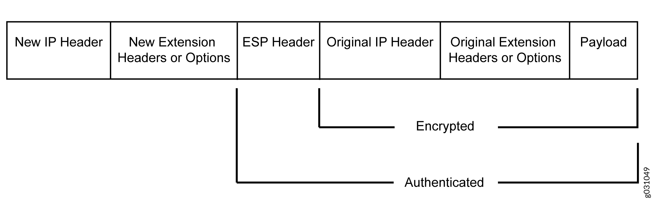
ESP Protocol in IPv6
ESP protocol provides both encryption and authentication for IPv6 packets. Because IPv6 IPsec uses extension headers (for example, hop-by-hop and routing options) in the IPv6 datagram, the most important difference between IPv6 ESP tunnel mode and IPv4 ESP tunnel mode is the placement of extension headers in the packet layout. In ESP tunnel mode, the ESP header immediately follows the new outer IPv6 header similar to that in IPv4 ESP tunnel mode. Therefore, in ESP tunnel mode, the entire packet is encapsulated by adding a new outer IPv6 header, followed by an ESP header, an inner header, extension headers, and the rest of the original datagram as shown in Figure 2.
IPv4 Options and IPv6 Extension Headers with AH and ESP
IPsec packets with IPv4 options or IPv6 extension headers can be received for decapsulation on firewalls.
See the Additional Platform Information section for more information.
The table shows the IPv4 options or IPv6 extension headers that are supported with the ESP or AH protocol on firewalls. If an unsupported IPsec packet is received, ICV calculation fails and the packet is dropped.
Integrity Check Value Calculation in IPv6
The AH protocol verifies the integrity of the IPv6 packet by computing an Integrity Check Value (ICV) on the packet contents. ICV is usually built over an authentication algorithm such as MD5 or SHA-1. The IPv6 ICV calculations differ from that in IPv4 in terms of two header fields—mutable header and optional extension header.
You can calculate the AH ICV over the IPv6 header fields that are either immutable in transit or predictable in value upon arrival at the tunnel endpoints. You can also calculate the AH ICV over the AH header and the upper level protocol data (considered to be immutable in transit). You can calculate the ESP ICV over the entire IPv6 packet, excluding the new outer IPv6 header and the optional extension headers.
Unlike IPv4, IPv6 has a method for tagging options as mutable in transit. IPv6 optional extension headers contain a flag that indicates mutability. This flag determines the appropriate processing.
IPv4 mutable options and IPv6 extension headers are not supported with the AH protocol.
Header Construction in Tunnel Modes
In tunnel mode, the source and destination addresses of the outer IPv4 or IPv6 header represent the tunnel endpoints, while the source and destination addresses of the inner IPv4 or IPv6 header represent the final source and destination addresses. Table 3 summarizes how the outer IPv6 header relates to the inner IPv6 or IPv4 header for IPv6-in-IPv6 or IPv4-in-IPv6 tunnel modes. In outer header fields, “Constructed” means that the value of the outer header field is constructed independently of the value in the inner header field.
|
Header Fields |
Outer Header at Encapsulator |
Inner Header at Decapsulator |
|---|---|---|
|
version |
6. |
No change. |
|
DS field |
Copied from the inner header. |
No change. |
|
ECN field |
Copied from the inner header. |
Constructed. |
|
flow label |
0. |
No change. |
|
payload length |
Constructed. |
No change. |
|
next header |
AH, ESP, and routing header. |
No change. |
|
hop limit |
64. |
Decrement. |
|
src address |
Constructed. |
No change. |
|
dest address |
Constructed. |
No change. |
|
Extension headers |
Never copied. |
No change. |
Table 4 summarizes how the outer IPv4 header relates to the inner IPv6 or IPv4 header for IPv6-in-IPv4 or IPv4-in-IPv4 tunnel modes. In outer header fields, “Constructed” means that the value of the outer header field is constructed independently of the value in the inner header field.
|
Header Fields |
Outer Header |
Inner Header |
|---|---|---|
|
version |
4. |
No change. |
|
header length |
Constructed. |
No change. |
|
DS field |
Copied from the inner header. |
No change. |
|
ECN field |
Copied from the inner header. |
Constructed. |
|
total length |
Constructed. |
No change. |
|
ID |
Constructed. |
No change. |
|
flags (DF, MF) |
Constructed. |
No change. |
|
fragment offset |
Constructed. |
No change. |
|
TTL |
64. |
Decrement. |
|
protocol |
AH, ESP |
No change. |
|
checksum |
Constructed. |
Constructed. |
|
src address |
Constructed. |
No change. |
|
dest address |
Constructed. |
No change. |
|
options |
Never copied. |
No change. |
For IPv6-in-IPv4 tunnel mode, the Don’t Fragment (DF)
bit is cleared by default. If the df-bit set or df-bit
copy options are configured at the [edit security ipsec
vpn vpn-name
] hierarchy level for the corresponding
IPv4 VPN, the DF bit is set in the outer IPv4 header.
For IPv4-in-IPv4 tunnel mode, the DF bit in the outer IPv4 header
is based on the df-bit option configured for the inner
IPv4 header. If df-bit is not configured for the inner
IPv4 header, the DF bit is cleared in the outer IPv4 header.
See Also
IPv6 IPsec Configuration Overview
Juniper Networks supports manual and autokey IKE with preshared keys configurations for IPv6 IPsec VPN.
AutoKey IKE VPN—In an autoKey IKE VPN configuration, the secret keys and SAs are automatically created using the autoKey IKE mechanism. To set up an IPv6 autoKey IKE VPN, two phases of negotiations are required—Phase 1 and Phase 2.
Phase 1—In this phase, the participants establish a secure channel for negotiating the IPsec SAs.
Phase 2—In this phase, the participants negotiate the IPsec SAs for authenticating and encrypting the IPv6 data packets.
For more information on Phase 1 and Phase 2 negotiations, see Internet Key Exchange
See Also
Example: Configuring an IPv6 IPsec Manual VPN
This example shows how to configure an IPv6 IPsec manual VPN.
Requirements
Before you begin:
Understand how VPNs work. See IPsec Overview.
Understand IPv6 IPsec packet processing. See Understanding IPv6 IKE and IPsec Packet Processing.
Overview
In a Manual VPN configuration, the secret keys are manually configured on the two IPsec endpoints.
In this example, you:
Configure the authentication parameters for a VPN named vpn-sunnyvale.
Configure the encryption parameters for vpn-sunnyvale.
Specify the outgoing interface for the SA.
Specify the IPv6 address of the peer.
Define the IPsec protocol. Select the ESP protocol because the configuration includes both authentication and encryption.
Configure a security parameter index (SPI).
Configuration
Procedure
CLI Quick Configuration
To quickly configure this example, copy the
following commands, paste them into a text file, remove any line breaks,
change any details necessary to match your network configuration,
copy and paste the commands into the CLI at the [edit] hierarchy
level, and then enter commit from configuration mode.
set security ipsec vpn vpn-sunnyvale manual authentication algorithm hmac-md5–96 key ascii-text “$ABC123”
set security ipsec vpn vpn-sunnyvale manual encryption algorithm 3des-cbc key ascii-text “$ABC123”
set security ipsec vpn vpn-sunnyvale manual external-interface ge-0/0/14.0
set security ipsec vpn vpn-sunnyvale manual gateway 2001:db8:1212::1112
set security ipsec vpn vpn-sunnyvale manual protocol esp
set security ipsec vpn vpn-sunnyvale manual spi 12435
Step-by-Step Procedure
The following example requires you to navigate various levels in the configuration hierarchy. For instructions on how to do that, see Using the CLI Editor in Configuration Mode in the CLI User Guide.
To configure security algorithms:
Configure the authentication parameters.
[edit security ipsec vpn vpn-sunnyvale manual]
user@host# set authentication algorithm hmac-md5–96 key ascii-text “$ABC123”
Configure the encryption parameters.
[edit security ipsec vpn vpn-sunnyvale manual]
user@host# set encryption algorithm 3des-cbc key ascii-text “$ABC123”
Specify the outgoing interface for the SA.
[edit security ipsec vpn vpn-sunnyvale manual]
user@host# set external-interface ge-0/0/14.0
Specify the IPv6 address of the peer.
[edit security ipsec vpn vpn-sunnyvale manual]
user@host# set gateway 2001:db8:1212::1112
Define the IPsec protocol.
[edit security ipsec vpn vpn-sunnyvale manual]
user@host# set protocol esp
Configure an SPI.
[edit security ipsec vpn vpn-sunnyvale manual]
user@host# set spi 12435
Results
From configuration mode, confirm your configuration
by entering the show security ipsec vpn vpn-sunnyvale command.
If the output does not display the intended configuration, repeat
the configuration instructions in this example to correct it.
[edit]
[user@host]show security ipsec vpn vpn-sunnyvale
manual {
gateway 2001:db8:1212::1112 ;
external-interface ge-0/0/14.0 ;
protocol esp ;
spi 12435 ;
authentication {
    algorithm hmac-md5-96 ;
    key ascii-text $ABC123” ;## SECRET DATA
}
    encryption {
        algorithm 3des-cbc ;
        key ascii-text $ABC123”; ## SECRET DATA
        }
    }
Platform-Specific IPv6 Tunnels Behavior
Use Feature Explorer to confirm platform and release support for specific features.
Use the following table to review platform-specific behavior for your platform.
| Platform | Difference |
|---|---|
| SRX Series |
|
Additional Platform Information
Use Feature Explorer to confirm platform and release support for specific features. Additional Platforms may be supported.
|
Options or Extension Headers |
SRX300SRX320SRX340SRX345 |
SRX400SRX440SRX440-2AC |
SRX5400SRX5600SRX5800 |
|---|---|---|---|
|
ESP with IPv4 options |
Supported |
Supported |
Supported |
|
ESP with IPv6 extension headers |
Supported |
Not supported |
Supported |
|
AH with IPv4 immutable options |
Supported |
Supported |
Supported |
|
AH with IPv6 immutable extension headers |
Supported |
Not supported |
Supported |
|
AH with IPv4 mutable options |
Not supported |
Not supported |
Not supported |
|
AH with IPv6 mutable extension headers |
Not supported |
Not supported |
Not supported |
Change History Table
Feature support is determined by the platform and release you are using. Use Feature Explorer to determine if a feature is supported on your platform.