AutoVPN on Hub-And-Spoke Devices
Learn about AutoVPN and how to configure the feature on the firewall.
AutoVPN supports an IPsec VPN aggregator (known as a hub) that serves as a single termination point for multiple tunnels to remote sites (known as spokes). AutoVPN allows network administrators to configure a hub for current and future spokes.
Use Feature Explorer to confirm platform and release support for specific features.
Review the Platform-Specific AutoVPN Behavior section for notes related to your platform.
See the Additional Platform Information section for more information.
Understanding AutoVPN
AutoVPN supports an IPsec VPN aggregator (known as a hub) that serves as a single termination point for multiple tunnels to remote sites (known as spokes). AutoVPN allows network administrators to configure a hub for current and future spokes. No configuration changes are required on the hub when spoke devices are added or deleted, thus allowing administrators flexibility in managing large-scale network deployments.
- Secure Tunnel Modes
- Authentication
- Configuration and Management
- Multicast Support Using PIM
- Understanding AutoVPN Limitations
- Understanding AutoVPN with Traffic Selectors
Secure Tunnel Modes
AutoVPN is supported on route-based IPsec VPNs. For route-based VPNs, you configure a secure tunnel (st0) interface and bind it to an IPsec VPN tunnel. st0 interfaces in AutoVPN networks can be configured in one of two modes:
-
Point-to-point mode—By default, a st0 interface configured at the [
edit
                     interfaces st0 unit x
] hierarchy level is in point-to-point mode. -
Point-to-multipoint mode—In this mode, the
multipointoption is configured at the [edit interfaces st0 unit x] hierarchy level on both AutoVPN hub and spokes. st0 interfaces on the hub and spokes must be numbered and the IP address configured on a spoke must exist in the hub's st0 interface subnetwork.
Table 1 compares AutoVPN point-to-point and point-to-multipoint secure tunnel interface modes.
|
Point-to-Point Mode |
Point-to-Multipoint Mode |
|---|---|
|
Supports IKEv1 or IKEv2. |
Supports IKEv1 or IKEv2. |
|
Supports IPv4 and IPv6 traffic. |
Supports IPv4 or IPv6. |
|
Traffic selectors |
Dynamic routing protocols (OSPF, OSPFv3 and iBGP) |
|
Dead peer detection |
Dead peer detection |
|
Allows spoke devices to be Juniper Networks firewall or third-party devices. |
This mode is only supported with Juniper Networks firewalls. |
Authentication
AutoVPNs support both certificate and preshared key based authentication methods.
For certificate based authentication in AutoVPN hubs and spokes, you can use X.509 public key infrastructure (PKI) certificates. The group IKE user type configured on the hub allows strings to be specified to match the alternate subject field in spoke certificates. Partial matches for the subject fields in spoke certificates can also be specified.
We support AutoVPN with the following two options:
- AutoVPN seeded PSK: Multiple peers connecting to same gateway having different pre-shared key.
- AutoVPN shared PSK: Multiple peers connecting to same gateway having same pre-shared key.
Seeded PSK is different from non-seeded PSK (that is, same shared PSK). Seeded PSK uses
master key to generate the shared PSK for the peer. So each peer will have different PSK
connecting to the same gateway. For example: Consider a scenario where peer 1 with the
IKE ID user1@juniper.net and peer 2 with IKE ID
user2@juniper.net attempts to connect to gateway. In this scenario
the gateway that is configured as HUB_GW containing the master key
configured as ThisIsMySecretPreSharedkey will have the different PSK as
follows:
Peer 1 : 79e4ea39f5c06834a3c4c031e37c6de24d46798a
Peer 2: 3db8385746f3d1e639435a882579a9f28464e5c7
This means, for different users with different user id and same master key will generate a different or unique preshared key.
You can use either seeded-pre-shared-key or
pre-shared-key for Auto-VPN PSK:
-
Different preshared key: If the
seeded-pre-shared-keyis set, different IKE preshared key is used by the VPN gateway to authenticate each remote peer. The peer preshared keys are generated using themaster-keyset in the IKE gateway and shared across the peers.To enable the VPN gateway to use a different IKE preshared key (PSK) for authenticating each remote peer, use the new CLI commands
seeded-pre-shared-key ascii-textorseeded-pre-shared-key hexadecimalunder the[edit security ike policy policy_name]hierarchy level.This command is mutually exclusive with
pre-shared-keycommand under the same hierarchy. -
Shared/Same preshared key: If
pre-shared-key-typeis not configured, then the PSK is considered to be shared. Same IKE preshared key is used by the VPN gateway to authenticate all remote peers.To enable the VPN gateway to use the same IKE PSK for authenticating all remote peers, use the existing CLI commands
pre-sharedkey ascii-textorpre-shared-key hexadecimal.
At the VPN gateway, you can bypass the IKE ID validation using the
general-ikeid configuration statement under the [edit
security ike gateway gateway_name dynamic] hierarchy
level. If this option is configured, then during authentication of remote peer, the VPN
gateway allows any remote IKE ID connection.
See Additional Platform Information to know about AutoVPN PSK support with different IKE modes in firewalls running the
iked process with the junos-ike package.
Configuration and Management
AutoVPN is configured and managed on firewalls using the CLI. Multiple AutoVPN hubs can be configured on a single firewall. The maximum number of spokes supported by a configured hub is specific to the model of the firewall.
Multicast Support Using PIM
IP multicast delivers traffic to more than one intended receivers by replicating the data packets. You can use multicast data for applications such as video streaming. Your firewall supports Protocol Independent Multicast (PIM) in point-to-multipoint (P2MP) mode. You can enable PIM on the firewall's secure tunnel, st0, interface with P2MP mode. The protocol detects the P2MP interface from the interface configuration and supports multicast traffic. To understand PIM, see PIM Overview.
Figure 1 illustrates multicast topology in P2MP infrastructure.
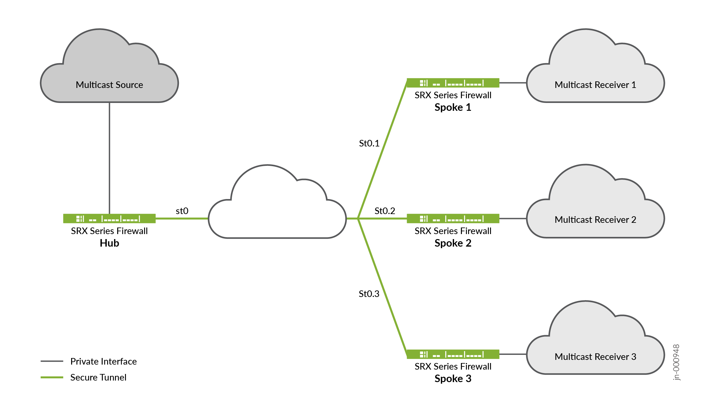
The topology shows that one of the firewalls acting as a hub and the rest of the three acting as spokes. You can also have two spokes in your topology. Typically, the multicast sender resides behind the hub, while the multicast receivers are behind the spokes. For multicast support, notice that the secure tunnel st0 logical interface on the hub-and-spoke devices are configured with PIM P2MP mode. On each of these devices, the st0 P2MP interface tracks all PIM joins per neighbor to ensure that the multicast forwarding or replication happens only to those neighbors that are in joined state.
The firewalls support IP multicast traffic in PIM sparse mode over the st0 P2MP interfaces. The hub acts as the first-hop router (FHR) or the rendezvous point (RP). The spokes can act as the last-hop routers (LHR) in the P2MP network. The devices in the network replicate the multicast data packets to neighbors that join the multicast group.
Note the following considerations when you configure multicast traffic support:
-
You cannot configure IPv6 multicast on P2MP interfaces.
-
For IP multicast configuration to work, you must disable PowerMode IPsec (PMI).
-
You cannot perform multicast ping from or to P2MP interfaces.
-
Note that IGMP is enable by default when you enable PIM, but it doesn't work on P2MP interface.
For details on how to configure multicast support on P2MP infrastructure, see Configure Multicast Support on P2MP Infrastructure.
Understanding AutoVPN Limitations
The following features are not supported for AutoVPN:
-
Policy-based VPNs are not supported.
-
The RIP dynamic routing protocol is not supported with AutoVPN tunnels.
-
Manual keys and Autokey IKE with preshared keys are not supported.
-
Configuring static next-hop tunnel binding (NHTB) on the hub for spokes is not supported.
-
IPv6 multicast is not supported.
-
The group IKE ID user type is not supported with an IP address as the IKE ID.
-
When the group IKE ID user type is used, the IKE ID should not overlap with other IKE gateways configured on the same external interface.
Understanding AutoVPN with Traffic Selectors
AutoVPN hubs can be configured with multiple traffic selectors to protect traffic to spokes. This feature provides the following benefits:
-
A single VPN configuration can support many different peers.
-
VPN peers can be third-party devices.
-
A single peer can establish multiple tunnels with the same VPN.
-
A larger number of tunnels can be supported than with AutoVPN with dynamic routing protocols.
AutoVPN networks that use secure tunnel interfaces in point-to-point mode support IPv6 addresses for traffic selectors and for IKE peers.
When the hub-to-spoke tunnel is established, the hub uses auto route insertion (ARI), known in previous releases as reverse route insertion (RRI), to insert the route to the spoke prefix in its routing table. The ARI route can then be imported to routing protocols and distributed to the core network.
AutoVPN with traffic selectors can be configured with the secure tunnel (st0) interface in point-to-point mode for both IKEv1 and IKEv2.
Dynamic routing protocols are not supported on st0 interfaces when traffic selectors are configured.
Note the following caveats when configuring AutoVPN with traffic selectors:
-
Dynamic routing protocols are not supported with traffic selectors with st0 interfaces in point-to-point mode.
-
Auto Discovery VPN and IKEv2 configuration payload cannot be configured with AutoVPN with traffic selectors.
-
Spokes can be third-party devices; however, note the following differences:
-
In IKEv2, a third-party spoke can propose multiple traffic selectors in a single SA negotiation. This is not supported on Juniper Networks firewalls and the negotiation is rejected.
-
A third-party spoke can identify specific ports or protocols for traffic selector use. Ports and protocols are not supported with traffic selectors on Juniper Networks firewalls and the negotiation is rejected.
-
See Also
Understanding Spoke Authentication in AutoVPN Deployments
In AutoVPN deployments, the hub and spoke devices must have valid X.509 PKI certificates loaded.
You can use the show security pki local-certificate detail command to
display information about the certificates loaded in a device.
This topic covers the configuration on the hub that allows spokes to authenticate and connect to the hub using certificates:
Group IKE ID Configuration on the Hub
The group IKE ID feature allows a number of spoke devices to share an IKE configuration on the hub. The certificate holder’s identification, in the subject or alternate subject fields in each spoke’s X.509 certificate, must contain a part that is common to all spokes; the common part of the certificate identification is specified for the IKE configuration on the hub.
For example, the IKE ID example.net can be configured
on the hub to identify spokes with the hostnames device1.example.net, device2.example.net, and device3.example.net. The certificate on each spoke must contain a hostname identity
in the alternate subject field with example.net in the
right-most part of the field; for example, device1.example.net. In this example, all spokes use this hostname identity in their
IKE ID payload. During IKE negotiation, the IKE ID from a spoke is
used to match the common part of the peer IKE identity configured
on the hub. A valid certificate authenticates the spoke.
The common part of the certificate identification can be one of the following:
A partial hostname in the right-most part of the alternate subject field of the certificate, for example
example.net.A partial e-mail address in the right-most part of the alternate subject field of the certificate, for example
@example.net.A container string, a set of wildcards, or both to match the subject fields of the certificate. The subject fields contain details of the digital certificate holder in Abstract Syntax Notation One (ASN.1) distinguished name (DN) format. Fields can include organization, organizational unit, country, locality, or common name.
To configure a group IKE ID to match subject fields in certificates, you can specify the following types of identity matches:
Container—The hub authenticates the spoke’s IKE ID if the subject fields of the spoke’s certificate exactly match the values configured on the hub. Multiple entries can be specified for each subject field (for example,
ou=eng,ou=sw). The order of values in the fields must match.Wildcard—The hub authenticates the spoke’s IKE ID if the subject fields of the spoke’s certificate match the values configured on the hub. Wildcard matching supports only one value per DN field in the configuration. For example, you can specify either
ou=engorou=sw. The CLI doesn't support multiple values such asou=eng, ou=sw. The order of DN fields does not affect the matching behavior.
The following example configures a group IKE ID with the partial
hostname example.net in the alternate subject field of
the certificate.
[edit]
security {
    ike {
        policy common-cert-policy {
            proposals common-ike-proposal;
            certificate {
                local-certificate hub-local-certificate;
            }
        }
        gateway common-gateway-to-all-spoke-peer {
            ike-policy common-cert-policy;
            dynamic {
                hostname example.net;
                ike-user-type group-ike-id;
            }
            external-interface fe-0/0/2;
        }
    }
}
In this example, example.net is the common part
of the hostname identification used for all spokes. All X.509 certificates
on the spokes must contain a hostname identity in the alternate subject
field with example.net in the right-most part. All spokes
must use the hostname identity in their IKE ID payload.
The following example configures a group IKE ID with wildcards
to match the values sales in the organizational unit and example in the organization subject fields of the certificate.
[edit]
security {
    ike {
        policy common-cert-policy {
            proposals common-ike-proposal;
            certificate {
                local-certificate hub-local-certificate;
            }
        }
        gateway common-gateway-to-all-spoke-peer {
            ike-policy common-cert-policy;
            dynamic {
                distinguished-name {
                    wildcard ou=sales,o=example;
                }
                ike-user-type group-ike-id;
            }
            external-interface fe-0/0/2;
        }
    }
}
In this example, the fields ou=sales,o=example are
the common part of the subject field in the certificates expected
from the spokes. During IKE negotiation, if a spoke presents a certificate
with the subject fields cn=alice,ou=sales,o=example in
its certificate, authentication succeeds and the tunnel is established.
If a spoke presents a certificate with the subject fields cn=thomas,ou=engineer,o=example in its certificate, the certificate is rejected by the hub as the
organization unit should be sales.
Excluding a Spoke Connection
To exclude a particular spoke from connecting to the hub, the certificate for that spoke must be revoked. The hub needs to retrieve the latest certificate revocation list (CRL) from the CA that contains the serial number of the revoked certificate. The hub will then refuse a VPN connection from the revoked spoke. Until the latest CRL is available in the hub, the hub might continue to establish a tunnel from the revoked spoke. For more information, see Enroll Certificate and Certificate Authority Profiles.
See Also
AutoVPN Configuration Overview
The following steps describe the basic tasks for configuring AutoVPN on hub and spoke devices. The AutoVPN hub is configured once for all current and new spokes.
To configure the AutoVPN hub:
To configure a Juniper Networks firewall AutoVPN spoke device:
Enroll a CA certificate and the local certificate in the device.
Use the preshared key based authentication method, if you configure preshared key authentication on the hub.
Create an st0 interface and configure it in point-to-multipoint mode.
Configure an IKE policy to match the IKE policy configured on the hub.
Configure an IKE gateway with an ID to match the group IKE ID configured on the hub.
Configure an IPsec policy to match the IPsec policy configured on the hub.
Configure a dynamic routing protocol.
The examples listed in this topic use firewalls running Junos OS for the hub and spoke configurations. If your spoke devices are not running Junos OS, you need to configure Next-Hop Tunnel Binding.
See Also
Example: Configuring Basic AutoVPN with iBGP
This example shows how to configure an AutoVPN hub to act as a single termination point, and then configure two spokes to act as tunnels to remote sites. This example configures iBGP to forward packets through the VPN tunnels and uses certificate based authentication.
For authentication with preshared key, see ‘Configure Phase 1 options’ step at Step-by-Step Procedure hub to configure the hub, Step-by-Step Procedure spoke1 to configure the spoke1, and the Step-by-Step Procedure spoke2 to configure the spoke2.
Requirements
This example uses the following hardware and software components:
-
Three supported Juniper Networks firewalls as AutoVPN hub and spokes
-
Junos OS Release that supports AutoVPN
Before you begin:
-
Obtain the address of the certificate authority (CA) and the information they require (such as the challenge password) when you submit requests for local certificates.
You should be familiar with the dynamic routing protocol that is used to forward packets through the VPN tunnels. For more information about specific requirements for a dynamic routing protocol, see the Routing Protocols Overview.
Overview
This example shows the configuration of an AutoVPN hub and the subsequent configurations of two spokes.
In this example, the first step is to enroll digital certificates in each device using the Simple Certificate Enrollment Protocol (SCEP). The certificates for the spokes contain the organizational unit (OU) value “SLT” in the subject field; the hub is configured with a group IKE ID to match the value “SLT” in the OU field.
The spokes establish IPsec VPN connections to the hub, which allows them to communicate with each other as well as access resources on the hub. Phase 1 and Phase 2 IKE tunnel options configured on the AutoVPN hub and all spokes must have the same values. Table 2 shows the options used in this example.
|
Option |
Value |
|---|---|
|
IKE proposal: |
|
|
Authentication method |
RSA digital certificates |
|
Diffie-Hellman (DH) group |
2 |
|
Authentication algorithm |
SHA-1 |
|
Encryption algorithm |
AES 128 CBC |
|
IKE policy: |
|
|
Mode |
Main |
|
IPsec proposal: |
|
|
Protocol |
ESP |
|
Authentication algorithm |
HMAC MD5 96 |
|
Encryption algorithm |
DES CBC |
|
IPsec policy: |
|
|
Perfect Forward Secrecy (PFS) group |
14 |
The same certificate authority (CA) is configured on all devices.
Junos OS only supports a single level of certificate hierarchy.
Table 3 shows the options configured on the hub and on all spokes.
|
Option |
Hub |
All Spokes |
|---|---|---|
|
IKE gateway: |
||
|
Remote IP address |
Dynamic |
10.1.1.1 |
|
Remote IKE ID |
Distinguished name (DN) on the spoke’s certificate with the
string |
DN on the hub’s certificate |
|
Local IKE ID |
DN on the hub’s certificate |
DN on the spoke’s certificate |
|
External interface |
ge-0/0/1.0 |
Spoke 1: fe-0/0/1.0 Spoke 2: ge-0/0/1.0 |
|
VPN: |
||
|
Bind interface |
st0.0 |
st0.0 |
|
Establish tunnels |
(not configured) |
Immediately on configuration commit |
Table 4 shows the configuration options that are different on each spoke.
|
Option |
Spoke 1 |
Spoke 2 |
|---|---|---|
|
st0.0 interface |
10.10.10.2/24 |
10.10.10.3/24 |
|
Interface to internal network |
(fe-0.0/4.0) 10.60.60.1/24 |
(fe-0.0/4.0) 10.70.70.1/24 |
|
Interface to Internet |
(fe-0/0/1.0) 10.2.2.1/30 |
(ge-0/0/1.0) 10.3.3.1/30 |
Routing information for all devices is exchanged through the VPN tunnels.
In this example, the default security policy that permits all traffic is used for all devices. More restrictive security policies should be configured for production environments.
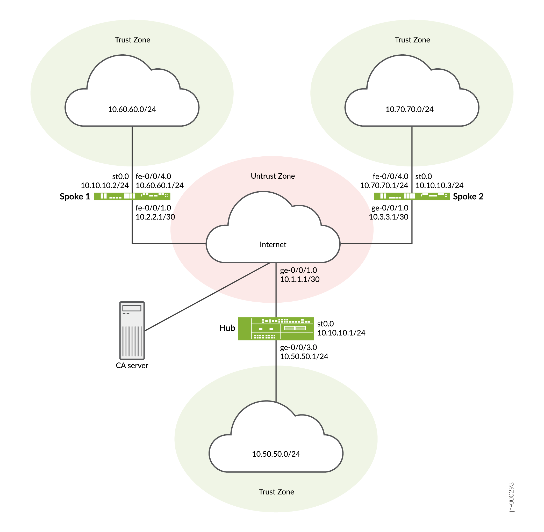
Topology
Figure 2 shows the firewalls to be configured for AutoVPN in this example.
Configuration
To configure AutoVPN, perform these tasks:
The first section describes how to obtain CA and local certificates online using the Simple Certificate Enrollment Protocol (SCEP) on the hub and spoke devices. Ignore this step, if you are using PSK.
Enroll Device Certificates with SCEP
Step-by-Step Procedure
To enroll digital certificates with SCEP on the hub:
-
Configure the CA.
[edit]
user@host# set security pki ca-profile ca-profile1 ca-identity ca-profile1
user@host# set security pki ca-profile ca-profile1 enrollment url http://pc4/certsrv/mscep/mscep.dll
user@host# set security pki ca-profile ca-profile1 revocation-check disable
user@host# commit
-
Enroll the CA certificate.
user@host> request security pki ca-certificate enroll ca-profile ca-profile1
Type yes at the prompt to load the CA certificate.
-
Generate a key pair.
user@host> request security pki generate-key-pair certificate-id Local1
-
Enroll the local certificate.
user@host> request security pki local-certificate enroll ca-profile ca-profile1 certificate-id Local1 domain-name example.net email hub@example.net ip-address 10.1.1.1 subject DC=example.net,CN=hub,OU=SLT,O=example,L=Bengaluru,ST=KA,C=IN challenge-password <password>
-
Verify the local certificate.
user@host> show security pki local-certificate detail

Certificate identifier: Local1
  Certificate version: 3
  Serial number: 40a6d5f300000000258d
  Issuer:
    Common name: CASERVER1, Domain component: net, Domain component: internal
  Subject:
    Organization: example, Organizational unit: SLT, Country: IN, State: KA,
    Locality: Bengaluru, Common name: hub, Domain component: example.net
  Subject string:
    C=IN, DC=example.net, ST=KA, L=Bengaluru, O=example, OU=SLT, CN=hub
  Alternate subject: "hub@example.net", example.net, 10.1.1.1
  Validity:
    Not before: 11- 6-2012 09:39
    Not after: 11- 6-2013 09:49
  Public key algorithm: rsaEncryption(1024 bits)
    30:81:89:02:81:81:00:c9:c9:cc:30:b6:7a:86:12:89:b5:18:b3:76
    01:2d:cc:65:a8:a8:42:78:cd:d0:9a:a2:c0:aa:c4:bd:da:af:88:f3
    2a:78:1f:0a:58:e6:11:2c:81:8f:0e:7c:de:86:fc:48:4c:28:5b:8b
    34:91:ff:2e:91:e7:b5:bd:79:12:de:39:46:d9:fb:5c:91:41:d1:da
    90:f5:09:00:9b:90:07:9d:50:92:7d:ff:fb:3f:3c:bc:34:e7:e3:c8
    ea:cb:99:18:b4:b6:1d:a8:99:d3:36:b9:1b:36:ef:3e:a1:fd:48:82
    6a:da:22:07:da:e0:d2:55:ef:57:be:09:7a:0e:17:02:03:01:00:01
  Signature algorithm: sha1WithRSAEncryption
  Distribution CRL:
    http://ca-server1/CertEnroll/CASERVER1.crl
    file://\\ca-server1\CertEnroll\CASERVER1.crl
  Fingerprint:
    e1:f7:a1:a6:1e:c3:97:69:a5:07:9b:09:14:1a:c7:ae:09:f1:f6:35 (sha1)
    a0:02:fa:8d:5c:63:e5:6d:f7:f4:78:56:ac:4e:b2:c4 (md5)
  Auto-re-enrollment:
    Status: Disabled
    Next trigger time: Timer not started
Step-by-Step Procedure
To enroll digital certificates with SCEP on spoke 1:
-
Configure the CA.
[edit]
user@host# set security pki ca-profile ca-profile1 ca-identity ca-profile1
user@host# set security pki ca-profile ca-profile1 enrollment url http://pc4/certsrv/mscep/mscep.dll
user@host# set security pki ca-profile ca-profile1 revocation-check disable
user@host# commit
-
Enroll the CA certificate.
user@host> request security pki ca-certificate enroll ca-profile ca-profile1
Type yes at the prompt to load the CA certificate.
-
Generate a key pair.
user@host> request security pki generate-key-pair certificate-id Local1
-
Enroll the local certificate.
user@host> request security pki local-certificate enroll ca-profile ca-profile1 certificate-id Local1 domain-name example.net email spoke1@example.net ip-address 10.2.2.1 subject DC=example.net,CN=spoke1,OU=SLT,O=example,L=Mysore,ST=KA,C=IN challenge-password <password>
-
Verify the local certificate.
user@host> show security pki local-certificate detail

Certificate identifier: Local1
  Certificate version: 3
  Serial number: 40a7975f00000000258e
  Issuer:
    Common name: CASERVER1, Domain component: net, Domain component: internal
  Subject:
    Organization: example, Organizational unit: SLT, Country: IN, State: KA,
    Locality: Mysore, Common name: spoke1, Domain component: example.net
  Subject string:
    C=IN, DC=example.net, ST=KA, L=Mysore, O=example, OU=SLT, CN=spoke1
  Alternate subject: "spoke1@example.net", example.net, 10.2.2.1
  Validity:
    Not before: 11- 6-2012 09:40
    Not after: 11- 6-2013 09:50
  Public key algorithm: rsaEncryption(1024 bits)
    30:81:89:02:81:81:00:d8:45:09:77:cd:36:9a:6f:58:44:18:91:db
    b0:c7:8a:ee:c8:d7:a6:d2:e2:e7:20:46:2b:26:1a:92:e2:4e:8a:ce
    c9:25:d9:74:a2:81:ad:ea:e0:38:a0:2f:2d:ab:a6:58:ac:88:35:f4
    90:01:08:33:33:75:2c:44:26:f8:25:18:97:96:e4:28:de:3b:35:f2
    4a:f5:92:b7:57:ae:73:4f:8e:56:71:ab:81:54:1d:75:88:77:13:64
    1b:6b:01:96:15:0a:1c:54:e3:db:f8:ec:ec:27:5b:86:39:c1:09:a1
    e4:24:1a:19:0d:14:2c:4b:94:a4:04:91:3f:cb:ef:02:03:01:00:01
  Signature algorithm: sha1WithRSAEncryption
  Distribution CRL:
    http://ca-server1/CertEnroll/CASERVER1.crl
    file://\\ca-server1\CertEnroll\CASERVER1.crl
  Fingerprint:
    b6:24:2a:0e:96:5d:8c:4a:11:f3:5a:24:89:7c:df:ea:d5:c0:80:56 (sha1)
    31:58:7f:15:bb:d4:66:b8:76:1a:42:4a:8a:16:b3:a9 (md5)
  Auto-re-enrollment:
    Status: Disabled
    Next trigger time: Timer not started
The organizational unit (OU) shown in the subject field is
SLT. The IKE configuration on the hub includesou=SLTto identify the spoke.
Step-by-Step Procedure
To enroll digital certificates with SCEP on spoke 2:
-
Configure the CA.
[edit]
user@host# set security pki ca-profile ca-profile1 ca-identity ca-profile1
user@host# set security pki ca-profile ca-profile1 enrollment url http://pc4/certsrv/mscep/mscep.dll
user@host# set security pki ca-profile ca-profile1 revocation-check disable
user@host# commit
-
Enroll the CA certificate.
user@host> request security pki ca-certificate enroll ca-profile ca-profile1
Type yes at the prompt to load the CA certificate.
-
Generate a key pair.
user@host> request security pki generate-key-pair certificate-id Local1
-
Enroll the local certificate.
user@host> request security pki local-certificate enroll ca-profile ca-profile1 certificate-id Local1 domain-name example.net email spoke2@example.net ip-address 10.3.3.1 subject DC=example.net,CN=spoke2,OU=SLT,O=example,L=Tumkur,ST=KA,C=IN challenge-password <password>
-
Verify the local certificate.
user@host> show security pki local-certificate detail

Certificate identifier: Local1
  Certificate version: 3
  Serial number: 40bb71d400000000258f
  Issuer:
    Common name: CASERVER1, Domain component: net, Domain component: internal
  Subject:
    Organization: example, Organizational unit: SLT, Country: IN, State: KA,
    Locality: Tumkur, Common name: spoke2, Domain component: example.net
  Subject string:
    C=IN, DC=example.net, ST=KA, L=Tumkur, O=example, OU=SLT, CN=spoke2
  Alternate subject: "spoke2@example.net", example.net, 10.3.3.1
  Validity:
    Not before: 11- 6-2012 10:02
    Not after: 11- 6-2013 10:12
  Public key algorithm: rsaEncryption(1024 bits)
    30:81:89:02:81:81:00:b6:2e:e2:da:e6:ac:57:e4:5d:ff:de:f6:89
    27:d6:3e:1b:4a:3f:b2:2d:b3:d3:61:ed:ed:6a:07:d9:8a:d2:24:03
    77:1a:fe:84:e1:12:8a:2d:63:6e:bf:02:6b:15:96:5a:4f:37:a0:46
    44:09:96:c0:fd:bb:ab:79:2c:5d:92:bd:31:f0:3b:29:51:ce:89:8e
    7c:2b:02:d0:14:5b:0a:a9:02:93:21:ea:f9:fc:4a:e7:08:bc:b1:6d
    7c:f8:3e:53:58:8e:f1:86:13:fe:78:b5:df:0b:8e:53:00:4a:46:11
    58:4a:38:e9:82:43:d8:25:47:7d:ef:18:f0:ef:a7:02:03:01:00:01
  Signature algorithm: sha1WithRSAEncryption
  Distribution CRL:
    http://ca-server1/CertEnroll/CASERVER1.crl
    file://\\ca-server1\CertEnroll\CASERVER1.crl
  Fingerprint:
    1a:6d:77:ac:fd:94:68:ce:cf:8a:85:f0:39:fc:e0:6b:fd:fe:b8:66 (sha1)
    00:b1:32:5f:7b:24:9c:e5:02:e6:72:75:9e:a5:f4:77 (md5)
  Auto-re-enrollment:
    Status: Disabled
    Next trigger time: Timer not started
The organizational unit (OU) shown in the subject field is
SLT. The IKE configuration on the hub includesou=SLTto identify the spoke.
Configuring the Hub
CLI Quick Configuration
To quickly configure this example, copy the following commands, paste them
into a text file, remove any line breaks, change any details necessary to
match your network configuration, copy and paste the commands into the CLI
at the [edit] hierarchy level, and then enter
commit from configuration mode.
set interfaces ge-0/0/1 unit 0 family inet address 10.1.1.1/30
set interfaces ge-0/0/3 unit 0 family inet address 10.50.50.1/24
set interfaces st0 unit 0 multipoint
set interfaces st0 unit 0 family inet address 10.10.10.1/24
set policy-options policy-statement lan_nw from interface ge-0/0/3.0
set policy-options policy-statement lan_nw then accept
set protocols bgp group ibgp type internal
set protocols bgp group ibgp local-address 10.10.10.1
set protocols bgp group ibgp export lan_nw
set protocols bgp group ibgp cluster 10.2.3.4
set protocols bgp group ibgp peer-as 65010
set policy-options policy-statement lan_nw from interface ge-0/0/3.0
set policy-options policy-statement lan_nw then accept
set policy-options policy-statement bgp_nh_self term 1 from protocol bgp
set policy-options policy-statement bgp_nh_self term 1 then next-hop self
set policy-options policy-statement bgp_nh_self term 1 then accept
set protocols bgp group ibgp export bgp_nh_self
set protocols bgp group ibgp allow 10.10.10.0/24
set routing-options static route 10.2.2.0/30 next-hop 10.1.1.2
set routing-options static route 10.3.3.0/30 next-hop 10.1.1.2
set routing-options autonomous-system 65010
set security ike proposal ike-proposal authentication-method rsa-signatures
set security ike proposal ike-proposal dh-group group2
set security ike proposal ike-proposal authentication-algorithm sha1
set security ike proposal ike-proposal encryption-algorithm aes-128-cbc
set security ike policy ike-policy1 mode main
set security ike policy ike-policy1 proposals ike-proposal
set security ike policy ike-policy1 certificate local-certificate Local1
set security ike gateway hub-to-spoke-gw ike-policy ike-policy1
set security ike gateway hub-to-spoke-gw dynamic distinguished-name wildcard OU=SLT
set security ike gateway hub-to-spoke-gw dynamic ike-user-type group-ike-id
set security ike gateway hub-to-spoke-gw local-identity distinguished-name
set security ike gateway hub-to-spoke-gw external-interface ge-0/0/1.0
set security ipsec proposal ipsec-proposal protocol esp
set security ipsec proposal ipsec-proposal authentication-algorithm hmac-md5-96
set security ipsec proposal ipsec-proposal encryption-algorithm des-cbc
set security ipsec policy vpn-policy1 perfect-forward-secrecy keys group14
set security ipsec policy vpn-policy1 proposals ipsec-proposal
set security ipsec vpn hub-to-spoke-vpn bind-interface st0.0
set security ipsec vpn hub-to-spoke-vpn ike gateway hub-to-spoke-gw
set security ipsec vpn hub-to-spoke-vpn ike ipsec-policy vpn-policy1
set security zones security-zone untrust host-inbound-traffic system-services all
set security zones security-zone untrust host-inbound-traffic protocols all
set security zones security-zone untrust interfaces st0.0
set security zones security-zone untrust interfaces ge-0/0/1.0
set security zones security-zone trust host-inbound-traffic system-services all
set security zones security-zone trust host-inbound-traffic protocols all
set security zones security-zone trust interfaces ge-0/0/3.0
set security policies default-policy permit-all
set security pki ca-profile ca-profile1 ca-identity ca-profile1
set security pki ca-profile ca-profile1 enrollment url http://pc4/certsrv/mscep/mscep.dll
set security pki ca-profile ca-profile1 revocation-check disable
Step-by-Step Procedure
The following example requires you to navigate various levels in the configuration hierarchy.
To configure the hub:
-
Configure the interfaces.
[edit interfaces]
user@host# set ge-0/0/1 unit 0 family inet address 10.1.1.1/30
user@host# set ge-0/0/3 unit 0 family inet address 10.50.50.1/24
user@host# set st0 unit 0 multipoint
user@host# set st0 unit 0 family inet address 10.10.10.1/24
-
Configure routing protocol.
[edit policy-options]
user@host# set policy-statement lan_nw from interface ge-0/0/3.0
user@host# set policy-statement lan_nw then accept
user@host# set policy-statement bgp_nh_self term 1 from protocol bgp
user@host# set policy-statement bgp_nh_self term 1 then next-hop self
user@host# set policy-statement bgp_nh_self term 1 then accept
[edit protocols bgp]
user@host# set group ibgp type internal
user@host# set group ibgp local-address 10.10.10.1
user@host# set group ibgp export lan_nw
user@host# set group ibgp cluster 10.2.3.4
user@host# set group ibgp peer-as 65010
user@host# set group ibgp allow 10.10.10.0/24
user@host# set group ibgp export bgp_nh_self
[edit routing-options]
user@host# set static route 10.2.2.0/30 next-hop 10.1.1.2
user@host# set static route 10.3.3.0/30 next-hop 10.1.1.2
user@host# set autonomous-system 65010
-
Configure Phase 1 options.
If you intend to use preshared keys instead of certificates for the authentication, make the following changes in your configuration:
In the ike proposal, at the [
edit security ike
                                            proposal ike-proposal
] hierarchy level, replaceauthentication-method rsa-signatureswith theauthentication-method pre-shared-keys.For details about the options, see proposal (Security IKE).
In the ike policy, at the [
edit security ike policy policy-name] hierarchy level, replacecertificate local-certificate Local1with thepre-shared-key ascii-text key.For example,
set pre-shared-key ascii-text juniper123
For details about the options, see policy (Security IKE).
In the ike gateway, at the [
edit security ike gateway hub-to-spoke-gw] hierarchy level,Replace
dynamic distinguished-name wildcard OU=SLTwith thedynamic hostname domain-name.For example,
set dynamic hostname juniper.netEnsure your device is able to resolve the hostname. Alternatively, you can use
set dynamic general-ikeidandset dynamic ike-user-type group-ike-idfor the spoke dynamic identity.
Replace
local-identity distinguished-namewith thelocal-identity hostname hub-hostname.For example,
set local-identity hostname hub.juniper.net.Ensure your device is able to resolve the hostname. Alternatively, you can use
inet ip-addressas inset local-identity inet 192.168.1.100.
For details about the options, see gateway (Security IKE).
[edit security ike proposal ike-proposal] user@host# set authentication-method rsa-signatures user@host# set dh-group group2 user@host# set authentication-algorithm sha1 user@host# set encryption-algorithm aes-128-cbc [edit security ike policy ike-policy1] user@host# set mode main user@host# set proposals ike-proposal user@host# set certificate local-certificate Local1 [edit security ike gateway hub-to-spoke-gw] user@host# set ike-policy ike-policy1 user@host# set dynamic distinguished-name wildcard OU=SLT user@host# set dynamic ike-user-type group-ike-id user@host# set local-identity distinguished-name user@host# set external-interface ge-0/0/1.0
-
Configure Phase 2 options.
[edit security ipsec proposal ipsec-proposal] user@host# set protocol esp user@host# set authentication-algorithm hmac-md5-96 user@host# set encryption-algorithm des-cbc [edit security ipsec policy vpn-policy1] user@host# set perfect-forward-secrecy keys group14 user@host# set proposals ipsec-proposal [edit security ipsec vpn hub-to-spoke-vpn] user@host# set bind-interface st0.0 user@host# set ike gateway hub-to-spoke-gw user@host# set ike ipsec-policy vpn-policy1
-
Configure zones.
[edit security zones security-zone untrust] user@host# set host-inbound-traffic system-services all user@host# set host-inbound-traffic protocols all user@host# set interfaces ge-0/0/1.0 user@host# set interfaces st0.0 [edit security zones security-zone trust] user@host# set host-inbound-traffic system-services all user@host# set host-inbound-traffic protocols all user@host# set interfaces ge-0/0/3.0
-
Configure the default security policy.
[edit security policies] user@host# set default-policy permit-all
-
Configure the CA profile. Ignore this step, if you are using PSK.
[edit security pki] user@host# set ca-profile ca-profile1 ca-identity ca-profile1 user@host# set ca-profile ca-profile1 enrollment url http://pc4/certsrv/mscep/mscep.dll user@host# set ca-profile ca-profile1 revocation-check disable
Results
From configuration mode, confirm your configuration by entering the
show interfaces, show policy-options,
show protocols, show routing-options,
show security ike, show security
ipsec, show security zones, show security
policies, and show security pki commands. If
the output does not display the intended configuration, repeat the
configuration instructions in this example to correct it.
[edit]
user@host# show interfaces
ge-0/0/1 {
unit 0 {
family inet {
address 10.1.1.1/30;
}
}
}
ge-0/0/3 {
unit 0 {
family inet {
address 10.50.50.1/24;
}
}
}
st0 {
unit 0 {
multipoint;
family inet {
address 10.10.10.1/24;
}
}
}
[edit]
user@host# show policy-options
policy-statement bgp_nh_self {
term 1 {
from protocol bgp;
then {
next-hop self;
accept;
}
}
}
policy-statement lan_nw {
from interface ge-0/0/3.0;
then accept;
}
[edit]
user@host# show protocols
bgp {
group ibgp {
type internal;
local-address 10.10.10.1;
export lan_nw;
cluster 10.2.3.4;
peer-as 65010;
allow 10.10.10.0/24;
export bgp_nh_self;
}
}
[edit]
user@host# show routing-options
static {
route 10.2.2.0/30 next-hop 10.1.1.2;
route 10.3.3.0/30 next-hop 10.1.1.2;
}
autonomous-system 65010;
[edit]
user@host# show security ike
proposal ike-proposal {
authentication-method rsa-signatures;
dh-group group2;
authentication-algorithm sha1;
encryption-algorithm aes-128-cbc;
}
policy ike-policy1 {
mode main;
proposals ike-proposal;
certificate {
local-certificate Local1;
}
}
gateway hub-to-spoke-gw {
ike-policy ike-policy1;
dynamic {
distinguished-name {
wildcard OU=SLT;
}
ike-user-type group-ike-id;
}
local-identity distinguished-name;
external-interface ge-0/0/1.0;
}
[edit]
user@host# show security ipsec
proposal ipsec-proposal {
protocol esp;
authentication-algorithm hmac-md5-96;
encryption-algorithm des-cbc;
}
policy vpn-policy1 {
perfect-forward-secrecy {
keys group14;
}
proposals ipsec-proposal;
}
vpn hub-to-spoke-vpn {
bind-interface st0.0;
ike {
gateway hub-to-spoke-gw;
ipsec-policy vpn-policy1;
}
}
[edit]
user@host# show security zones
security-zone untrust {
host-inbound-traffic {
system-services {
all;
}
protocols {
all;
}
}
interfaces {
st0.0;
ge-0/0/1.0;
}
}
security-zone trust {
host-inbound-traffic {
system-services {
all;
}
protocols {
all;
}
}
interfaces {
ge-0/0/3.0;
}
}
[edit]
user@host# show security policies
default-policy {
permit-all;
}
[edit]
user@host# show security pki
ca-profile ca-profile1 {
ca-identity ca-profile1;
enrollment {
url http://pc4/certsrv/mscep/mscep.dll;
}
revocation-check {
disable;
}
}
If you are done configuring the device, enter commit from
configuration mode.
Configuring Spoke 1
CLI Quick Configuration
To quickly configure this example, copy the following commands, paste them
into a text file, remove any line breaks, change any details necessary to
match your network configuration, copy and paste the commands into the CLI
at the [edit] hierarchy level, and then enter
commit from configuration mode.
set interfaces fe-0/0/1 unit 0 family inet address 10.2.2.1/30 set interfaces fe-0/0/4 unit 0 family inet address 10.60.60.1/24 set interfaces st0 unit 0 multipoint set interfaces st0 unit 0 family inet address 10.10.10.2/24 set policy-options policy-statement lan_nw from interface fe-0/0/4.0 set policy-options policy-statement lan_nw then accept set protocols bgp group ibgp type internal set protocols bgp group ibgp local-address 10.10.10.2 set protocols bgp group ibgp export lan_nw set protocols bgp group ibgp neighbor 10.10.10.1 set routing-options static route 10.1.1.0/30 next-hop 10.2.2.2 set routing-options autonomous-system 65010 set security ike proposal ike-proposal authentication-method rsa-signatures set security ike proposal ike-proposal dh-group group2 set security ike proposal ike-proposal authentication-algorithm sha1 set security ike proposal ike-proposal encryption-algorithm aes-128-cbc set security ike policy ike-policy1 mode main set security ike policy ike-policy1 proposals ike-proposal set security ike policy ike-policy1 certificate local-certificate Local1 set security ike gateway spoke-to-hub-gw ike-policy ike-policy1 set security ike gateway spoke-to-hub-gw address 10.1.1.1 set security ike gateway spoke-to-hub-gw local-identity distinguished-name set security ike gateway spoke-to-hub-gw remote-identity distinguished-name set security ike gateway spoke-to-hub-gw external-interface fe-0/0/1.0 set security ipsec proposal ipsec-proposal protocol esp set security ipsec proposal ipsec-proposal authentication-algorithm hmac-md5-96 set security ipsec proposal ipsec-proposal encryption-algorithm des-cbc set security ipsec policy vpn-policy1 perfect-forward-secrecy keys group14 set security ipsec policy vpn-policy1 proposals ipsec-proposal set security ipsec vpn spoke-to-hub bind-interface st0.0 set security ipsec vpn spoke-to-hub ike gateway spoke-to-hub-gw set security ipsec vpn spoke-to-hub ike ipsec-policy vpn-policy1 set security ipsec vpn spoke-to-hub establish-tunnels immediately set security zones security-zone untrust host-inbound-traffic system-services all set security zones security-zone untrust host-inbound-traffic protocols all set security zones security-zone untrust interfaces fe-0/0/1.0 set security zones security-zone untrust interfaces st0.0 set security zones security-zone trust host-inbound-traffic system-services all set security zones security-zone trust host-inbound-traffic protocols all set security zones security-zone trust interfaces fe-0/0/4.0 set security policies default-policy permit-all set security pki ca-profile ca-profile1 ca-identity ca-profile1 set security pki ca-profile ca-profile1 enrollment url http://pc4/certsrv/mscep/mscep.dll set security pki ca-profile ca-profile1 revocation-check disable
Step-by-Step Procedure
The following example requires you to navigate various levels in the configuration hierarchy.
To configure spoke 1:
-
Configure interfaces.
[edit interfaces] user@host# set fe-0/0/1 unit 0 family inet address 10.2.2.1/30 user@host# set fe-0/0/4 unit 0 family inet address 10.60.60.1/24 user@host# set st0 unit 0 multipoint user@host# set st0 unit 0 family inet address 10.10.10.2/24
-
Configure routing protocol.
[edit policy-options] user@host# set policy-statement lan_nw from interface fe-0/0/4.0 user@host# set policy-statement lan_nw then accept [edit protocols bgp] user@host# set group ibgp type internal user@host# set group ibgp local-address 10.10.10.2 user@host# set group ibgp export lan_nw user@host# set group ibgp neighbor 10.10.10.1 [edit routing-options] user@host# set static route 10.1.1.0/30 next-hop 10.2.2.2 user@host# set autonomous-system 65010
-
Configure Phase 1 options.
If you intend to use preshared keys instead of certificates for the authentication, make the following changes in your configuration.
In the ike proposal, at the [
edit security ike proposal ike-proposal] hierarchy level, replaceauthentication-method rsa-signatureswith theauthentication-method pre-shared-keys.In the ike policy, at the [
edit security ike policy policy-name] hierarchy level, replacecertificate local-certificate Local1with thepre-shared-key ascii-text key.In the ike gateway, at the [
edit security ike gateway hub-to-spoke-gw] hierarchy level,Replace
local-identity distinguished-namewith thelocal-identity hostname spoke1-hostname.For example,
set local-identity hostname spoke1.juniper.net.
Replace
remote-identity distinguished-namewith theremote-identity hostname hub-hostname.For example,
set remote-identity hostname hub.juniper.net
Ensure your device is able to resolve the hostname. Alternatively, you can use
inet ip-addressas inset local-identity inet 172.16.1.100andset remote-identity inet 192.168.1.100.
[edit security ike proposal ike-proposal] user@host# set authentication-method rsa-signatures user@host# set dh-group group2 user@host# set authentication-algorithm sha1 user@host# set encryption-algorithm aes-128-cbc [edit security ike policy ike-policy1] user@host# set mode main user@host# set proposals ike-proposal user@host# set certificate local-certificate Local1 [edit security ike gateway spoke-to-hub-gw] user@host# set ike-policy ike-policy1 user@host# set address 10.1.1.1 user@host# set local-identity distinguished-name user@host# set remote-identity distinguished-name user@host# set external-interface fe-0/0/1.0
-
Configure Phase 2 options.
[edit security ipsec proposal ipsec-proposal] user@host# set protocol esp user@host# set authentication-algorithm hmac-md5-96 user@host# set encryption-algorithm des-cbc [edit security ipsec policy vpn-policy1] user@host# set perfect-forward-secrecy keys group14 user@host# set proposals ipsec-proposal [edit security ipsec vpn spoke-to-hub] user@host# set bind-interface st0.0 user@host# set ike gateway spoke-to-hub-gw user@host# set ike ipsec-policy vpn-policy1 user@host# set establish-tunnels immediately
-
Configure zones.
[edit security zones security-zone untrust] user@host# set host-inbound-traffic system-services all user@host# set host-inbound-traffic protocols all user@host# set interfaces fe-0/0/1.0 user@host# set interfaces st0.0 [edit security zones security-zone trust] user@host# set host-inbound-traffic system-services all user@host# set host-inbound-traffic protocols all user@host# set interfaces fe-0/0/4.0
-
Configure the default security policy.
[edit security policies] user@host# set default-policy permit-all
-
Configure the CA profile. Ignore this step, if you are using PSK.
[edit security pki] user@host# set ca-profile ca-profile1 ca-identity ca-profile1 user@host# set ca-profile ca-profile1 enrollment url http://pc4/certsrv/mscep/mscep.dll user@host# set ca-profile ca-profile1 revocation-check disable
Results
From configuration mode, confirm your configuration by entering the
show interfaces, show policy-options,
show protocols, show routing-options,
show security ike, show security
ipsec, show security zones, show security
policies, and show security pki commands. If
the output does not display the intended configuration, repeat the
configuration instructions in this example to correct it.
[edit]
user@host# show interfaces
fe-0/0/1 {
unit 0 {
family inet {
address 10.2.2.1/30;
}
}
}
fe-0/0/4 {
unit 0 {
family inet {
address 10.60.60.1/24;
}
}
}
st0 {
unit 0 {
multipoint;
family inet {
address 10.10.10.2/24;
}
}
}
[edit]
user@host# show policy-options
policy-statement lan_nw {
from interface fe-0/0/4.0;
then accept;
}
[edit]
user@host# show protocols
bgp {
group ibgp {
type internal;
local-address 10.10.10.2;
export lan_nw;
neighbor 10.10.10.1;
}
}
[edit]
user@host# show routing-options
static {
route 10.1.1.0/30 next-hop 10.2.2.2;
}
autonomous-system 65010;
[edit]
user@host# show security ike
proposal ike-proposal {
authentication-method rsa-signatures;
dh-group group2;
authentication-algorithm sha1;
encryption-algorithm aes-128-cbc;
}
policy ike-policy1 {
mode main;
proposals ike-proposal;
certificate {
local-certificate Local1;
}
}
gateway spoke-to-hub-gw {
ike-policy ike-policy1;
address 10.1.1.1;
local-identity distinguished-name;
remote-identity distinguished-name;
external-interface fe-0/0/1.0;
}
[edit]
user@host# show security ipsec
proposal ipsec-proposal {
protocol esp;
authentication-algorithm hmac-md5-96;
encryption-algorithm des-cbc;
}
policy vpn-policy1 {
perfect-forward-secrecy {
keys group14;
}
proposals ipsec-proposal;
}
vpn spoke-to-hub {
bind-interface st0.0;
ike {
gateway spoke-to-hub-gw;
ipsec-policy vpn-policy1;
}
establish-tunnels immediately;
}
[edit]
user@host# show security zones
security-zone untrust {
host-inbound-traffic {
system-services {
all;
}
protocols {
all;
}
}
interfaces {
fe-0/0/1.0;
st0.0;
}
}
security-zone trust {
host-inbound-traffic {
system-services {
all;
}
protocols {
all;
}
}
interfaces {
fe-0/0/4.0;
}
}
[edit]
user@host# show security policies
default-policy {
permit-all;
}
[edit]
user@host# show security pki
ca-profile ca-profile1 {
ca-identity ca-profile1;
enrollment {
url http://pc4/certsrv/mscep/mscep.dll;
}
revocation-check {
disable;
}
}
If you are done configuring the device, enter commit from
configuration mode.
Configuring Spoke 2
CLI Quick Configuration
To quickly configure this example, copy the following commands, paste them
into a text file, remove any line breaks, change any details necessary to
match your network configuration, copy and paste the commands into the CLI
at the [edit] hierarchy level, and then enter
commit from configuration mode.
set interfaces ge-0/0/1 unit 0 family inet address 10.3.3.1/30 set interfaces fe-0/0/4 unit 0 family inet address 10.70.70.1/24 set interfaces st0 unit 0 multipoint set interfaces st0 unit 0 family inet address 10.10.10.3/24 set policy-options policy-statement lan_nw from interface fe-0/0/4.0 set policy-options policy-statement lan_nw then accept set protocols bgp group ibgp type internal set protocols bgp group ibgp local-address 10.10.10.3 set protocols bgp group ibgp export lan_nw set protocols bgp group ibgp neighbor 10.10.10.1 set routing-options static route 10.1.1.0/30 next-hop 10.3.3.2 set routing-options autonomous-system 65010 set security ike proposal ike-proposal authentication-method rsa-signatures set security ike proposal ike-proposal dh-group group2 set security ike proposal ike-proposal authentication-algorithm sha1 set security ike proposal ike-proposal encryption-algorithm aes-128-cbc set security ike policy ike-policy1 mode main set security ike policy ike-policy1 proposals ike-proposal set security ike policy ike-policy1 certificate local-certificate Local1 set security ike gateway spoke-to-hub-gw ike-policy ike-policy1 set security ike gateway spoke-to-hub-gw address 10.1.1.1 set security ike gateway spoke-to-hub-gw local-identity distinguished-name set security ike gateway spoke-to-hub-gw remote-identity distinguished-name set security ike gateway spoke-to-hub-gw external-interface ge-0/0/1.0 set security ipsec proposal ipsec-proposal protocol esp set security ipsec proposal ipsec-proposal authentication-algorithm hmac-md5-96 set security ipsec proposal ipsec-proposal encryption-algorithm des-cbc set security ipsec policy vpn-policy1 perfect-forward-secrecy keys group14 set security ipsec policy vpn-policy1 proposals ipsec-proposal set security ipsec vpn spoke-to-hub bind-interface st0.0 set security ipsec vpn spoke-to-hub ike gateway spoke-to-hub-gw set security ipsec vpn spoke-to-hub ike ipsec-policy vpn-policy1 set security ipsec vpn spoke-to-hub establish-tunnels immediately set security zones security-zone untrust host-inbound-traffic system-services all set security zones security-zone untrust host-inbound-traffic protocols all set security zones security-zone untrust interfaces ge-0/0/1.0 set security zones security-zone untrust interfaces st0.0 set security zones security-zone trust host-inbound-traffic system-services all set security zones security-zone trust host-inbound-traffic protocols all set security zones security-zone trust interfaces fe-0/0/4.0 set security policies default-policy permit-all set security pki ca-profile ca-profile1 ca-identity ca-profile1 set security pki ca-profile ca-profile1 enrollment url http://pc4/certsrv/mscep/mscep.dll set security pki ca-profile ca-profile1 revocation-check disable
Step-by-Step Procedure
The following example requires you to navigate various levels in the configuration hierarchy.
To configure spoke 2:
-
Configure interfaces.
[edit interfaces] user@host# set ge-0/0/1 unit 0 family inet address 10.3.3.1/30 user@host# set fe-0/0/4 unit 0 family inet address 10.70.70.1/24 user@host# set st0 unit 0 multipoint user@host# set st0 unit 0 family inet address 10.10.10.3/24
-
Configure routing protocol.
[edit policy-options] user@host# set policy-statement lan_nw from interface fe-0/0/4.0 user@host# set policy-statement lan_nw then accept [edit protocols bgp] user@host# set group ibgp type internal user@host# set group ibgp local-address 10.10.10.3 user@host# set group ibgp export lan_nw user@host# set group ibgp neighbor 10.10.10.1 [edit routing-options] user@host# set static route 10.1.1.0/30 next-hop 10.3.3.2 user@host# set autonomous-system 65010
-
Configure Phase 1 options.
If you intend to use preshared keys instead of certificates for the authentication, make the following changes in your configuration.
In the ike proposal, at the [
edit security ike proposal ike-proposal] hierarchy level, replaceauthentication-method rsa-signatureswith theauthentication-method pre-shared-keys.In the ike policy, at the [
edit security ike policy policy-name] hierarchy level, replacecertificate local-certificate Local1with thepre-shared-key ascii-text key.In the ike gateway, at the [
edit security ike gateway hub-to-spoke-gw] hierarchy level,Replace
local-identity distinguished-namewith thelocal-identity hostname spoke2-hostname.For example,
set local-identity hostname spoke2.juniper.net
Replace
remote-identity distinguished-namewith theremote-identity hostname hub-hostname.For example,
set remote-identity hostname hub.juniper.net
Ensure your device is able to resolve the hostname. Alternatively, you can use
inet ip-addressas inset local-identity inet 10.0.1.100andset remote-identity inet 192.168.1.100.
[edit security ike proposal ike-proposal] user@host# set authentication-method rsa-signatures user@host# set dh-group group2 user@host# set authentication-algorithm sha1 user@host# set encryption-algorithm aes-128-cbc [edit security ike policy ike-policy1] user@host# set mode main user@host# set proposals ike-proposal user@host# set certificate local-certificate Local1 [edit security ike gateway spoke-to-hub-gw] user@host# set ike-policy ike-policy1 user@host# set address 10.1.1.1 user@host# set local-identity distinguished-name user@host# set remote-identity distinguished-name user@host# set external-interface ge-0/0/1.0
-
Configure Phase 2 options.
[edit security ipsec proposal ipsec-proposal] user@host# set protocol esp user@host# set authentication-algorithm hmac-md5-96 user@host# set encryption-algorithm des-cbc [edit security ipsec policy vpn-policy1] user@host# set perfect-forward-secrecy keys group14 user@host# set proposals ipsec-proposal [edit security ipsec vpn spoke-to-hub] user@host# set bind-interface st0.0 user@host# set ike gateway spoke-to-hub-gw user@host# set ike ipsec-policy vpn-policy1 user@host# set establish-tunnels immediately
-
Configure zones.
[edit security zones security-zone untrust] user@host# set host-inbound-traffic system-services all user@host# set host-inbound-traffic protocols all user@host# set interfaces ge-0/0/1.0 user@host# set interfaces st0.0 [edit security zones security-zone trust] user@host# set host-inbound-traffic system-services all user@host# set host-inbound-traffic protocols all user@host# set interfaces fe-0/0/4.0
-
Configure the default security policy.
[edit security policies] user@host# set default-policy permit-all
-
Configure the CA profile. Ignore this step, if you are using PSK.
[edit security pki] user@host# set ca-profile ca-profile1 ca-identity ca-profile1 user@host# set ca-profile ca-profile1 enrollment url http://pc4/certsrv/mscep/mscep.dll user@host# set ca-profile ca-profile1 revocation-check disable
Results
From configuration mode, confirm your configuration by entering the
show interfaces, show policy-options,
show protocols, show routing-options,
show security ike, show security
ipsec, show security zones, show security
policies, and show security pki commands. If
the output does not display the intended configuration, repeat the
configuration instructions in this example to correct it.
[edit]
user@host# show interfaces
ge-0/0/1 {
unit 0 {
family inet {
address 10.3.3.1/30;
}
}
}
fe-0/0/4 {
unit 0 {
family inet {
address 10.70.70.1/24;
}
}
}
st0 {
unit 0 {
multipoint;
family inet {
address 10.10.10.3/24;
}
}
}
[edit]
user@host# show policy-options
policy-statement lan_nw {
from interface fe-0/0/4.0;
then accept;
}
[edit]
user@host# show protocols
bgp {
group ibgp {
type internal;
local-address 10.10.10.3;
export lan_nw;
neighbor 10.10.10.1;
}
}
[edit]
user@host# show routing-options
static {
route 10.1.1.0/30 next-hop 10.3.3.2;
}
autonomous-system 65010;
[edit]
user@host# show security ike
proposal ike-proposal {
authentication-method rsa-signatures;
dh-group group2;
authentication-algorithm sha1;
encryption-algorithm aes-128-cbc;
}
policy ike-policy1 {
mode main;
proposals ike-proposal;
certificate {
local-certificate Local1;
}
}
gateway spoke-to-hub-gw {
ike-policy ike-policy1;
address 10.1.1.1;
local-identity distinguished-name;
remote-identity distinguished-name;
external-interface ge-0/0/1.0;
}
[edit]
user@host# show security ipsec
proposal ipsec-proposal {
protocol esp;
authentication-algorithm hmac-md5-96;
encryption-algorithm des-cbc;
}
policy vpn-policy1 {
perfect-forward-secrecy {
keys group14;
}
proposals ipsec-proposal;
}
vpn spoke-to-hub {
bind-interface st0.0;
ike {
gateway spoke-to-hub-gw;
ipsec-policy vpn-policy1;
}
establish-tunnels immediately;
}
[edit]
user@host# show security zones
security-zone untrust {
host-inbound-traffic {
system-services {
all;
}
protocols {
all;
}
}
interfaces {
ge-0/0/1.0;
st0.0;
}
}
security-zone trust {
host-inbound-traffic {
system-services {
all;
}
protocols {
all;
}
}
interfaces {
fe-0/0/4.0;
}
}
[edit]
user@host# show security policies
default-policy {
permit-all;
}
[edit]
user@host# show security pki
ca-profile ca-profile1 {
ca-identity ca-profile1;
enrollment {
url http://pc4/certsrv/mscep/mscep.dll;
}
revocation-check {
disable;
}
}
If you are done configuring the device, enter commit from
configuration mode.
Verification
Confirm that the configuration is working properly.
- Verifying IKE Phase 1 Status
- Verifying IPsec Phase 2 Status
- Verifying IPsec Next-Hop Tunnels
- Verifying BGP
- Verifying Learned Routes
Verifying IKE Phase 1 Status
Purpose
Verify the IKE Phase 1 status.
Action
From operational mode, enter the show security ike security-associations command.
user@host> show security ike security-associations Index State Initiator cookie Responder cookie Mode Remote Address 5480163 UP a558717f387074ab 6d0135c5ecaed61d Main 10.3.3.1 5480162 UP 7a63d16a5a723df1 c471f7ae166d3a34 Main 10.2.2.1
Meaning
The show security ike security-associations command lists
all active IKE Phase 1 SAs. If no SAs are listed, there was a problem with
Phase 1 establishment. Check the IKE policy parameters and external
interface settings in your configuration. Phase 1 proposal parameters must
match on the hub and spokes.
Verifying IPsec Phase 2 Status
Purpose
Verify the IPsec Phase 2 status.
Action
From operational mode, enter the security ipsec security-associations command.
user@host> security ipsec security-associations Total active tunnels: 2 ID Algorithm SPI Life:sec/kb Mon vsys Port Gateway <268173400 ESP:des/ md5 9bf33bc7 3567/ unlim - root 500 10.2.2.1 >268173400 ESP:des/ md5 aae5196b 3567/ unlim - root 500 10.2.2.1 <268173401 ESP:des/ md5 69c24d81 622/ unlim - root 500 10.3.3.1 >268173401 ESP:des/ md5 e3fe0231 622/ unlim - root 500 10.3.3.1
Meaning
The show security ipsec security-associations command lists
all active IKE Phase 2 SAs. If no SAs are listed, there was a problem with
Phase 2 establishment. Check the IKE policy parameters and external
interface settings in your configuration. Phase 2 proposal parameters must
match on the hub and spokes.
Verifying IPsec Next-Hop Tunnels
Purpose
Verify the IPsec next-hop tunnels.
Action
From operational mode, enter the show security ipsec next-hop-tunnels command.
user@host> show security ipsec next-hop-tunnels Next-hop gateway interface IPSec VPN name Flag IKE-ID XAUTH username 10.10.10.2 st0.0 hub-to-spoke-vpn Auto C=IN, DC=example.net, ST=KA, L=Mysore, O=example, OU=SLT, CN=spoke1 10.10.10.3 st0.0 hub-to-spoke-vpn Auto C=IN, DC=example.net, ST=KA, L=Tumkur, O=example, OU=SLT, CN=spoke2
Meaning
The next-hop gateways are the IP addresses for the st0
interfaces of the spokes. The next hop should be associated with the correct
IPsec VPN name.
Verifying BGP
Purpose
Verify that BGP references the IP addresses for the st0
interfaces of the spokes.
Action
From operational mode, enter the show bgp summary command.
user@host> show bgp summary Groups: 1 Peers: 2 Down peers: 0 Unconfigured peers: 2 Table Tot Paths Act Paths Suppressed History Damp State Pending inet.0 2 2 0 0 0 0 Peer AS InPkt OutPkt OutQ Flaps Last Up/Dwn State|#Active/Received/Accepted/Damped... 10.10.10.2 10 116 119 0 0 50:25 1/1/1/0 0/0/0/0 10.10.10.3 10 114 114 0 0 50:04 1/1/1/0 0/0/0/0
Verifying Learned Routes
Purpose
Verify that routes to the spokes have been learned.
Action
From operational mode, enter the show route 10.60.60.0 command.
user@host> show route 10.60.60.0
inet.0: 45 destinations, 45 routes (44 active, 0 holddown, 1 hidden)
+ = Active Route, - = Last Active, * = Both
10.60.60.0/24 *[BGP/170] 00:50:57, localpref 100
AS path: I
> to 10.10.10.2 via st0.0
From operational mode, enter the show route 10.70.70.0 command.
user@host> show route 10.70.70.0
inet.0: 45 destinations, 45 routes (44 active, 0 holddown, 1 hidden)
+ = Active Route, - = Last Active, * = Both
10.70.70.0/24 *[BGP/170] 00:50:42, localpref 100
AS path: I
> to 10.10.10.3 via st0.0
Example: Configuring Basic AutoVPN with iBGP for IPv6 Traffic
This example shows how to configure an AutoVPN hub to act as a single termination point, and then configure two spokes to act as tunnels to remote sites. This example configures AutoVPN for IPv6 environment using iBGP to forward packets through the VPN tunnels using the certificate based authentication. For authentication with preshared key, set up a similar configuration shown at Example: Configuring Basic AutoVPN with iBGP.
Requirements
This example uses the following hardware and software components:
-
Three supported firewalls as AutoVPN hub and spokes.
-
Supported Junos OS Release.
Before you begin:
-
Obtain the address of the certificate authority (CA) and the information they require (such as the challenge password) when you submit requests for local certificates.
You should be familiar with the dynamic routing protocol that is used to forward packets through the VPN tunnels. For more information about specific requirements for a dynamic routing protocol, see the Routing Protocols Overview.
Overview
This example shows the configuration of an AutoVPN hub and the subsequent configurations of two spokes .
In this example, the first step is to enroll digital certificates in each device using the Simple Certificate Enrollment Protocol (SCEP). The certificates for the spokes contain the organizational unit (OU) value “SLT” in the subject field; the hub is configured with a group IKE ID to match the value “SLT” in the OU field.
The spokes establish IPsec VPN connections to the hub, which allows them to communicate with each other as well as access resources on the hub. Phase 1 and Phase 2 IKE tunnel options configured on the AutoVPN hub and all spokes must have the same values. Table 5 shows the options used in this example.
|
Option |
Value |
|---|---|
|
IKE proposal: |
|
|
Authentication method |
RSA digital certificates |
|
Diffie-Hellman (DH) group |
19 |
|
Authentication algorithm |
SHA-384 |
|
Encryption algorithm |
AES 256 CBC |
|
IKE policy: |
|
|
Mode |
Main |
|
IPsec proposal: |
|
|
Protocol |
ESP |
|
Lifetime Seconds |
3000 |
|
Encryption algorithm |
AES 256 GCM |
|
IPsec policy: |
|
|
Perfect Forward Secrecy (PFS) group |
19 |
The same certificate authority (CA) is configured on all devices.
Junos OS only supports a single level of certificate hierarchy.
Table 6 shows the options configured on the hub and on all spokes.
|
Option |
Hub |
All Spokes |
|---|---|---|
|
IKE gateway: |
||
|
Remote IP address |
Dynamic |
2001:db8:2000::1 |
|
Remote IKE ID |
Distinguished name (DN) on the spoke’s certificate with the
string |
DN on the hub’s certificate |
|
Local IKE ID |
DN on the hub’s certificate |
DN on the spoke’s certificate |
|
External interface |
ge-0/0/0 |
Spoke 1: ge-0/0/0.0 Spoke 2: ge-0/0/0.0 |
|
VPN: |
||
|
Bind interface |
st0.1 |
st0.1 |
|
Establish tunnels |
(not configured) |
establish-tunnels on-traffic |
Table 7 shows the configuration options that are different on each spoke.
|
Option |
Spoke 1 |
Spoke 2 |
|---|---|---|
|
st0.0 interface |
2001:db8:7000::2/64 |
2001:db8:7000::3/64 |
|
Interface to internal network |
(ge-0/0/1.0) 2001:db8:4000::1/64 |
(ge-0/0/1.0) 2001:db8:6000::1/64 |
|
Interface to Internet |
(ge-0/0/0.0) 2001:db8:3000::2/64 |
(ge-0/0/0.0) 2001:db8:5000::2/64 |
Routing information for all devices is exchanged through the VPN tunnels.
In this example, the default security policy that permits all traffic is used for all devices. More restrictive security policies should be configured for production environments.
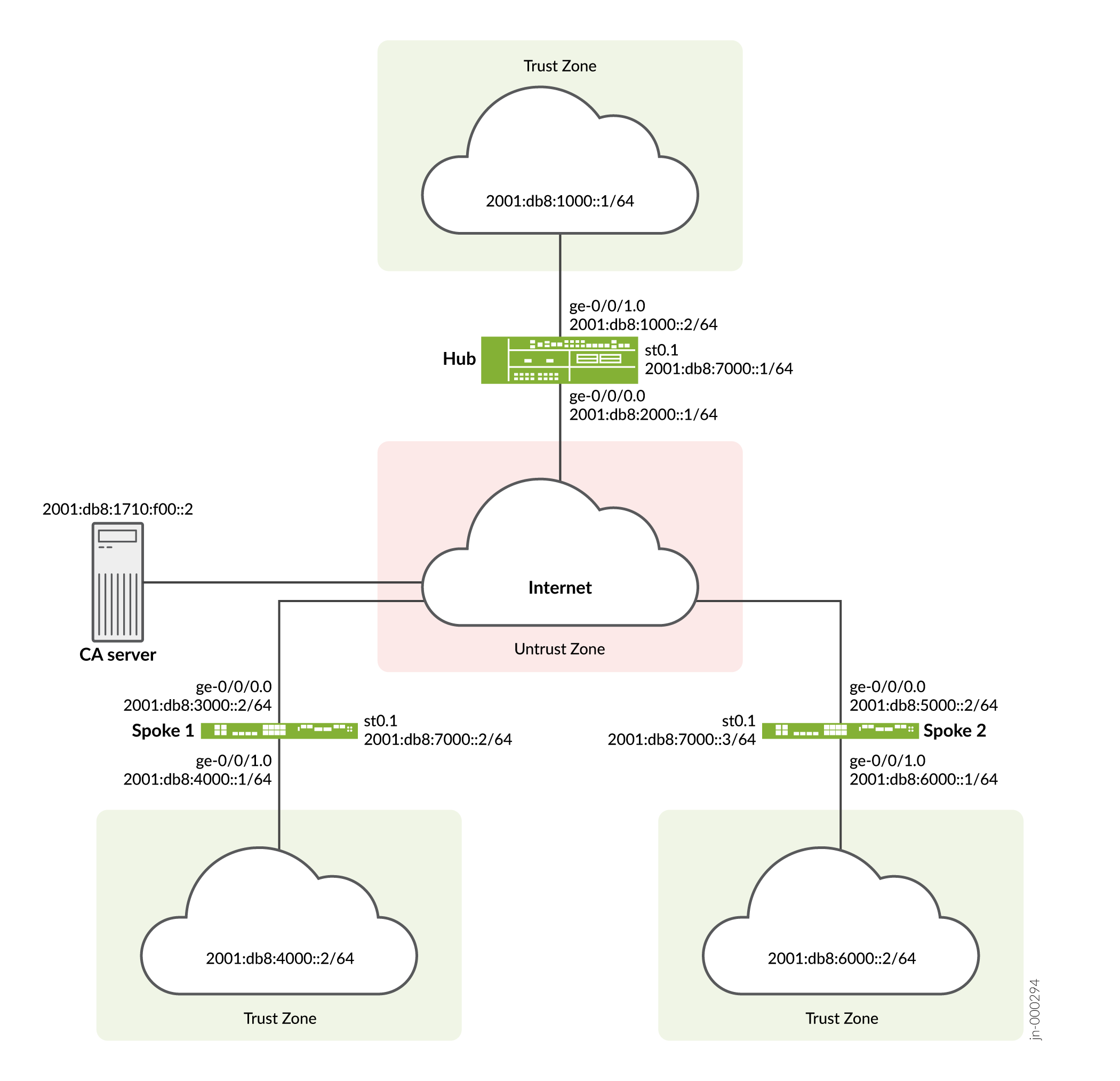
Topology
Figure 3 shows the firewalls to be configured for AutoVPN in this example.
Configuration
To configure AutoVPN, perform these tasks:
The first section describes how to obtain CA and local certificates online using the Simple Certificate Enrollment Protocol (SCEP) on the hub and spoke devices.
Enroll Device Certificates with SCEP
Step-by-Step Procedure
To enroll digital certificates with SCEP on the hub:
-
Configure the CA.
[edit] user@host# set security pki ca-profile ca-profile1 ca-identity ca-profile1 user@host# set security pki ca-profile ca-profile1 enrollment url http://2001:db8:1710:f00::2/certsrv/mscep/mscep.dll user@host# set security pki ca-profile ca-profile1 revocation-check disable user@host# commit
-
Enroll the CA certificate.
user@host> request security pki ca-certificate enroll ca-profile ca-profile1
Type yes at the prompt to load the CA certificate.
-
Generate a key pair.
user@host> request security pki generate-key-pair certificate-id Local1
-
Enroll the local certificate.
user@host> request security pki local-certificate enroll ca-profile ca-profile1 certificate-id Local1 domain-name example.net email hub@example.net ip-address 10.1.1.1 subject DC=example.net,CN=hub,OU=SLT,O=example,L=Bengaluru,ST=KA,C=IN challenge-password <password>
-
Verify the local certificate.
user@host> show security pki local-certificate detail Certificate identifier: Local1 Certificate version: 3 Serial number: 40a6d5f300000000258d Issuer: Common name: CASERVER1, Domain component: net, Domain component: internal Subject: Organization: example, Organizational unit: SLT, Country: IN, State: KA, Locality: Bengaluru, Common name: hub, Domain component: example.net Subject string: C=IN, DC=example.net, ST=KA, L=Bengaluru, O=example, OU=SLT, CN=hub Alternate subject: "hub@example.net", example.net, 10.1.1.1 Validity: Not before: 11- 6-2012 09:39 Not after: 11- 6-2013 09:49 Public key algorithm: rsaEncryption(1024 bits) 30:81:89:02:81:81:00:c9:c9:cc:30:b6:7a:86:12:89:b5:18:b3:76 01:2d:cc:65:a8:a8:42:78:cd:d0:9a:a2:c0:aa:c4:bd:da:af:88:f3 2a:78:1f:0a:58:e6:11:2c:81:8f:0e:7c:de:86:fc:48:4c:28:5b:8b 34:91:ff:2e:91:e7:b5:bd:79:12:de:39:46:d9:fb:5c:91:41:d1:da 90:f5:09:00:9b:90:07:9d:50:92:7d:ff:fb:3f:3c:bc:34:e7:e3:c8 ea:cb:99:18:b4:b6:1d:a8:99:d3:36:b9:1b:36:ef:3e:a1:fd:48:82 6a:da:22:07:da:e0:d2:55:ef:57:be:09:7a:0e:17:02:03:01:00:01 Signature algorithm: sha1WithRSAEncryption Distribution CRL: http://ca-server1/CertEnroll/CASERVER1.crl file://\\ca-server1\CertEnroll\CASERVER1.crl Fingerprint: e1:f7:a1:a6:1e:c3:97:69:a5:07:9b:09:14:1a:c7:ae:09:f1:f6:35 (sha1) a0:02:fa:8d:5c:63:e5:6d:f7:f4:78:56:ac:4e:b2:c4 (md5) Auto-re-enrollment: Status: Disabled Next trigger time: Timer not started
Step-by-Step Procedure
To enroll digital certificates with SCEP on spoke 1:
-
Configure the CA.
[edit] user@host# set security pki ca-profile ca-profile1 ca-identity ca-profile1 user@host# set security pki ca-profile ca-profile1 enrollment url http://2001:db8:1710:f00::2/certsrv/mscep/mscep.dll user@host# set security pki ca-profile ca-profile1 revocation-check disable user@host# commit
-
Enroll the CA certificate.
user@host> request security pki ca-certificate enroll ca-profile ca-profile1
Type yes at the prompt to load the CA certificate.
-
Generate a key pair.
user@host> request security pki generate-key-pair certificate-id Local1
-
Enroll the local certificate.
user@host> request security pki local-certificate enroll ca-profile ca-profile1 certificate-id Local1 domain-name example.net email spoke1@example.net ip-address 10.2.2.1 subject DC=example.net,CN=spoke1,OU=SLT,O=example,L=Mysore,ST=KA,C=IN challenge-password <password>
-
Verify the local certificate.
user@host> show security pki local-certificate detail Certificate identifier: Local1 Certificate version: 3 Serial number: 40a7975f00000000258e Issuer: Common name: CASERVER1, Domain component: net, Domain component: internal Subject: Organization: example, Organizational unit: SLT, Country: IN, State: KA, Locality: Mysore, Common name: spoke1, Domain component: example.net Subject string: C=IN, DC=example.net, ST=KA, L=Mysore, O=example, OU=SLT, CN=spoke1 Alternate subject: "spoke1@example.net", example.net, 10.2.2.1 Validity: Not before: 11- 6-2012 09:40 Not after: 11- 6-2013 09:50 Public key algorithm: rsaEncryption(1024 bits) 30:81:89:02:81:81:00:d8:45:09:77:cd:36:9a:6f:58:44:18:91:db b0:c7:8a:ee:c8:d7:a6:d2:e2:e7:20:46:2b:26:1a:92:e2:4e:8a:ce c9:25:d9:74:a2:81:ad:ea:e0:38:a0:2f:2d:ab:a6:58:ac:88:35:f4 90:01:08:33:33:75:2c:44:26:f8:25:18:97:96:e4:28:de:3b:35:f2 4a:f5:92:b7:57:ae:73:4f:8e:56:71:ab:81:54:1d:75:88:77:13:64 1b:6b:01:96:15:0a:1c:54:e3:db:f8:ec:ec:27:5b:86:39:c1:09:a1 e4:24:1a:19:0d:14:2c:4b:94:a4:04:91:3f:cb:ef:02:03:01:00:01 Signature algorithm: sha1WithRSAEncryption Distribution CRL: http://ca-server1/CertEnroll/CASERVER1.crl file://\\ca-server1\CertEnroll\CASERVER1.crl Fingerprint: b6:24:2a:0e:96:5d:8c:4a:11:f3:5a:24:89:7c:df:ea:d5:c0:80:56 (sha1) 31:58:7f:15:bb:d4:66:b8:76:1a:42:4a:8a:16:b3:a9 (md5) Auto-re-enrollment: Status: Disabled Next trigger time: Timer not startedThe organizational unit (OU) shown in the subject field is
SLT. The IKE configuration on the hub includesou=SLTto identify the spoke.
Step-by-Step Procedure
To enroll digital certificates with SCEP on spoke 2:
-
Configure the CA.
[edit] user@host# set security pki ca-profile ca-profile1 ca-identity ca-profile1 user@host# set security pki ca-profile ca-profile1 enrollment url http://2001:db8:1710:f00::2/certsrv/mscep/mscep.dll user@host# set security pki ca-profile ca-profile1 revocation-check disable user@host# commit
-
Enroll the CA certificate.
user@host> request security pki ca-certificate enroll ca-profile ca-profile1
Type yes at the prompt to load the CA certificate.
-
Generate a key pair.
user@host> request security pki generate-key-pair certificate-id Local1
-
Enroll the local certificate.
user@host> request security pki local-certificate enroll ca-profile ca-profile1 certificate-id Local1 domain-name example.net email spoke2@example.net ip-address 10.3.3.1 subject DC=example.net,CN=spoke2,OU=SLT,O=example,L=Tumkur,ST=KA,C=IN challenge-password <password>
-
Verify the local certificate.
user@host> show security pki local-certificate detail Certificate identifier: Local1 Certificate version: 3 Serial number: 40bb71d400000000258f Issuer: Common name: CASERVER1, Domain component: net, Domain component: internal Subject: Organization: example, Organizational unit: SLT, Country: IN, State: KA, Locality: Tumkur, Common name: spoke2, Domain component: example.net Subject string: C=IN, DC=example.net, ST=KA, L=Tumkur, O=example, OU=SLT, CN=spoke2 Alternate subject: "spoke2@example.net", example.net, 10.3.3.1 Validity: Not before: 11- 6-2012 10:02 Not after: 11- 6-2013 10:12 Public key algorithm: rsaEncryption(1024 bits) 30:81:89:02:81:81:00:b6:2e:e2:da:e6:ac:57:e4:5d:ff:de:f6:89 27:d6:3e:1b:4a:3f:b2:2d:b3:d3:61:ed:ed:6a:07:d9:8a:d2:24:03 77:1a:fe:84:e1:12:8a:2d:63:6e:bf:02:6b:15:96:5a:4f:37:a0:46 44:09:96:c0:fd:bb:ab:79:2c:5d:92:bd:31:f0:3b:29:51:ce:89:8e 7c:2b:02:d0:14:5b:0a:a9:02:93:21:ea:f9:fc:4a:e7:08:bc:b1:6d 7c:f8:3e:53:58:8e:f1:86:13:fe:78:b5:df:0b:8e:53:00:4a:46:11 58:4a:38:e9:82:43:d8:25:47:7d:ef:18:f0:ef:a7:02:03:01:00:01 Signature algorithm: sha1WithRSAEncryption Distribution CRL: http://ca-server1/CertEnroll/CASERVER1.crl file://\\ca-server1\CertEnroll\CASERVER1.crl Fingerprint: 1a:6d:77:ac:fd:94:68:ce:cf:8a:85:f0:39:fc:e0:6b:fd:fe:b8:66 (sha1) 00:b1:32:5f:7b:24:9c:e5:02:e6:72:75:9e:a5:f4:77 (md5) Auto-re-enrollment: Status: Disabled Next trigger time: Timer not startedThe organizational unit (OU) shown in the subject field is
SLT. The IKE configuration on the hub includesou=SLTto identify the spoke.
Configuring the Hub
CLI Quick Configuration
To quickly configure this example, copy the following commands, paste them
into a text file, remove any line breaks, change any details necessary to
match your network configuration, copy and paste the commands into the CLI
at the [edit] hierarchy level, and then enter
commit from configuration mode.
set security pki ca-profile ROOT-CA ca-identity ROOT-CA set security pki ca-profile ROOT-CA enrollment url http://2001:db8:1710:f00::2/certsrv/mscep/mscep.dll set security pki ca-profile ROOT-CA enrollment retry 5 set security pki ca-profile ROOT-CA enrollment retry-interval 0 set security pki ca-profile ROOT-CA revocation-check disable set security ike traceoptions file ik set security ike traceoptions flag all set security ike proposal IKE_PROP authentication-method rsa-signatures set security ike proposal IKE_PROP dh-group group19 set security ike proposal IKE_PROP authentication-algorithm sha-384 set security ike proposal IKE_PROP encryption-algorithm aes-256-cbc set security ike proposal IKE_PROP lifetime-seconds 6000 set security ike policy IKE_POL mode main set security ike policy IKE_POL proposals IKE_PROP set security ike policy IKE_POL certificate local-certificate HUB set security ike gateway IKE_GWA_1 ike-policy IKE_POL set security ike gateway IKE_GWA_1 dynamic distinguished-name wildcard OU=SLT set security ike gateway IKE_GWA_1 dead-peer-detection always-send set security ike gateway IKE_GWA_1 dead-peer-detection interval 10 set security ike gateway IKE_GWA_1 dead-peer-detection threshold 3 set security ike gateway IKE_GWA_1 local-identity distinguished-name set security ike gateway IKE_GWA_1 external-interface ge-0/0/0 set security ike gateway IKE_GWA_1 version v1-only set security ipsec proposal IPSEC_PROP protocol esp set security ipsec proposal IPSEC_PROP encryption-algorithm aes-256-gcm set security ipsec proposal IPSEC_PROP lifetime-seconds 3000 set security ipsec policy IPSEC_POL perfect-forward-secrecy keys group19 set security ipsec policy IPSEC_POL proposals IPSEC_PROP set security ipsec vpn IPSEC_VPNA_1 bind-interface st0.1 set security ipsec vpn IPSEC_VPNA_1 ike gateway IKE_GWA_1 set security ipsec vpn IPSEC_VPNA_1 ike ipsec-policy IPSEC_POL set security policies default-policy permit-all set security zones security-zone untrust host-inbound-traffic system-services all set security zones security-zone untrust host-inbound-traffic protocols ospf3 set security zones security-zone untrust interfaces ge-0/0/1.0 set security zones security-zone untrust interfaces st0.1 set security zones security-zone trust host-inbound-traffic system-services all set security zones security-zone trust host-inbound-traffic protocols ospf3 set security zones security-zone trust interfaces ge-0/0/0.0 set interfaces ge-0/0/0 unit 0 family inet6 address 2001:db8:2000::1/64 set interfaces ge-0/0/1 unit 0 family inet6 address 2001:db8:1000::2/64 set interfaces st0 unit 1 multipoint set interfaces st0 unit 1 family inet6 address 2001:db8:7000::1/64 set routing-options rib inet6.0 static route 2001:db8:3000::/64 next-hop 2001:db8:2000::2 set routing-options rib inet6.0 static route 2001:db8:5000::/64 next-hop 2001:db8:2000::2 set routing-options autonomous-system 100 set routing-options forwarding-table export load_balance set protocols bgp traceoptions file bgp set protocols bgp traceoptions flag all set protocols bgp group ibgp type internal set protocols bgp group ibgp local-address 2001:db8:9000::1 set protocols bgp group ibgp export ibgp set protocols bgp group ibgp cluster 10.1.3.4 set protocols bgp group ibgp peer-as 100 set protocols bgp group ibgp multipath set protocols bgp group ibgp allow 2001:db8:9000::/64 set policy-options policy-statement ibgp from interface ge-0/0/1.0 set policy-options policy-statement ibgp then accept set policy-options policy-statement load_balance then load-balance per-packet
Step-by-Step Procedure
The following example requires you to navigate various levels in the configuration hierarchy.
To configure the hub:
-
Configure the interfaces.
[edit interfaces] user@host# set ge-0/0/0 unit 0 family inet6 address 2001:db8:2000::1/64 user@host# set ge-0/0/1 unit 0 family inet6 address 2001:db8:1000::2/64 user@host# set st0 unit 1 multipoint user@host# set st0 unit 1 family inet6 address 2001:db8:7000::1/64
-
Configure routing protocol.
[edit policy-options] user@host# set policy-statement ibgp from interface ge-0/0/1.0 user@host# set policy-statement ibgp then accept user@host# set policy-statement load_balance then load-balance per-packet [edit protocols bgp] user@host# set traceoptions file bgp user@host# set traceoptions flag all user@host# set group ibgp type internal user@host# set group ibgp local-address 2001:db8:9000::1 user@host# set group ibgp export ibgp user@host# set group ibgp cluster 10.1.3.4 user@host# set group ibgp peer-as 100 user@host# set group ibgp multipath user@host# set group ibgp allow 2001:db8:9000::/64 [edit routing-options] user@host# set rib inet6.0 static route 2001:db8:3000::/64 next-hop 2001:db8:2000::2 user@host# set rib inet6.0 static route 2001:db8:5000::/64 next-hop 2001:db8:2000::2 user@host# set autonomous-system 100 user@host# set forwarding-table export load_balance
-
Configure Phase 1 options.
[edit security ike traceoptions] user@host# set file ik user@host# set flag all [edit security ike proposal ike-proposal IKE_PROP] user@host# set authentication-method rsa-signatures user@host# set dh-group group19 user@host# set authentication-algorithm sha-384 user@host# set encryption-algorithm aes-256-cbc user@host# set lifetime-seconds 6000 [edit security ike policy IKE_POL] user@host# set mode main user@host# set proposals IKE_PROP user@host# set certificate local-certificate HUB [edit security ike gateway IKE_GWA_1] user@host# set ike-policy IKE_POL user@host# set dynamic distinguished-name wildcard OU=SLT user@host# set dead-peer-detection always-send user@host# set dead-peer-detection interval 10 user@host# set dead-peer-detection threshold 3 user@host# set local-identity distinguished-name user@host# set external-interface ge-0/0/0 user@host# set version v1-only
-
Configure Phase 2 options.
[edit security ipsec proposal IPSEC_PROP] user@host# set protocol esp user@host# set encryption-algorithm aes-256-gcm user@host# set lifetime-seconds 3000 [edit security ipsec policy IPSEC_POL] user@host# set perfect-forward-secrecy keys group19 user@host# set proposals IPSEC_PROP [edit security ipsec vpn IPSEC_VPNA_1] user@host# set bind-interface st0.1 user@host# set ike gateway IKE_GWA_1 user@host# set ike ipsec-policy IPSEC_POL
-
Configure zones.
[edit security zones security-zone untrust] user@host# set host-inbound-traffic system-services all user@host# set host-inbound-traffic protocols ospf3 user@host# set interfaces ge-0/0/1.0 user@host# set interfaces st0.1 [edit security zones security-zone trust] user@host# set host-inbound-traffic system-services all user@host# set host-inbound-traffic protocols ospf3 user@host# set interfaces ge-0/0/0.0
-
Configure the default security policy.
[edit security policies] user@host# set default-policy permit-all
-
Configure the CA profile.
[edit security pki] user@host# set ca-profile ROOT-CA ca-identity ROOT-CA user@host# set ca-profile ROOT-CA enrollment url http://2001:db8:1710:f00::2/certsrv/mscep/mscep.dll user@host# set ca-profile ROOT-CA enrollment retry 5 user@host# set ca-profile ROOT-CA enrollment retry-interval 0 user@host# set ca-profile ROOT-CA revocation-check disable
Results
From configuration mode, confirm your configuration by entering the
show interfaces, show policy-options,
show protocols, show routing-options,
show security ike, show security
ipsec, show security zones, show security
policies, and show security pki commands. If
the output does not display the intended configuration, repeat the
configuration instructions in this example to correct it.
[edit]
user@host# show interfaces
ge-0/0/0 {
unit 0 {
family inet6 {
address 2001:db8:2000::1/64;
}
}
}
ge-0/0/1 {
unit 0 {
family inet6 {
address 2001:db8:1000::2/64;
}
}
}
st0 {
unit 1{
multipoint;
family inet6 {
address 2001:db8:7000::1/64;
}
}
}
[edit]
user@host# show policy-options
policy-statement ibgp {
from interface ge-0/0/1.0;
then accept;
}
policy-statement load_balance {
then {
load-balance per-packet;
}
}
[edit]
user@host# show protocols
bgp {
traceoptions {
file bgp;
flag all;
}
group ibgp {
type internal;
local-address 2001:db8:9000::1;
export ibgp;
cluster 10.1.3.4;
peer-as 100;
multipath;
allow 2001:db8:9000::/64;
}
}
[edit]
user@host# show routing-options
rib inet6.0 {
static {
route route 2001:db8:3000::/64 next-hop 2001:db8:2000::2;
route 2001:db8:5000::/64 next-hop 2001:db8:2000::2;
}
}
[edit]
user@host# show security ike
traceoptions {
file ik;
flag all;
}
proposal IKE_PROP {
authentication-method rsa-signatures;
dh-group group19;
authentication-algorithm sha-384;
encryption-algorithm aes-256-cbc;
lifetime-seconds 6000;
}
policy IKE_POL {
mode main;
proposals IKE_PROP;
certificate {
local-certificate HUB;
}
}
gateway IKE_GWA_1 {
ike-policy IKE_POL;
dynamic {
distinguished-name {
wildcard OU=SLT;
}
}
dead-peer-detection {
always-send;
interval 10;
threshold 3;
}
local-identity distinguished-name;
external-interface ge-0/0/0;
version v1-only;
}
[edit]
user@host# show security ipsec
proposal IPSEC_PROP {
protocol esp;
encryption-algorithm aes-256-gcm;
lifetime-seconds 3000;
}
policy IPSEC_POL {
perfect-forward-secrecy {
keys group19;
}
proposals IPSEC_PROP;
}
vpn IPSEC_VPNA_1 {
bind-interface st0.1;
ike {
gateway IKE_GWA_1;
ipsec-policy IPSEC_POL;
}
}
[edit]
user@host# show security zones
security-zone untrust {
host-inbound-traffic {
system-services {
all;
}
protocols {
ospf3;
}
}
interfaces {
ge-0/0/1.0;
st0.1;
}
}
security-zone trust {
host-inbound-traffic {
system-services {
all;
}
protocols {
ospf3;
}
}
interfaces {
ge-0/0/0.0;
}
}
[edit]
user@host# show security policies
default-policy {
permit-all;
}
[edit]
user@host# show security pki
ca-profile ROOT-CA {
ca-identity ROOT-CA;
enrollment {
url http://2001:db8:1710:f00::2/certsrv/mscep/mscep.dll;
retry 5;
retry-interval 0;
}
revocation-check {
disable;
}
}
If you are done configuring the device, enter commit from
configuration mode.
Configuring Spoke 1
CLI Quick Configuration
To quickly configure this example, copy the following commands, paste them
into a text file, remove any line breaks, change any details necessary to
match your network configuration, copy and paste the commands into the CLI
at the [edit] hierarchy level, and then enter
commit from configuration mode.
set security pki ca-profile ROOT-CA ca-identity ROOT-CA set security pki ca-profile ROOT-CA enrollment url http://2001:db8:1710:f00::2/certsrv/mscep/mscep.dll set security pki ca-profile ROOT-CA enrollment retry 5 set security pki ca-profile ROOT-CA enrollment retry-interval 0 set security pki ca-profile ROOT-CA revocation-check disable set security ike traceoptions file ik set security ike traceoptions flag all set security ike proposal IKE_PROP authentication-method rsa-signatures set security ike proposal IKE_PROP dh-group group19 set security ike proposal IKE_PROP authentication-algorithm sha-384 set security ike proposal IKE_PROP encryption-algorithm aes-256-cbc set security ike proposal IKE_PROP lifetime-seconds 6000 set security ike policy IKE_POL mode main set security ike policy IKE_POL proposals IKE_PROP set security ike policy IKE_POL certificate local-certificate SPOKE1 set security ike gateway IKE_GW_SPOKE_1 ike-policy IKE_POL set security ike gateway IKE_GW_SPOKE_1 address 2001:db8:2000::1 set security ike gateway IKE_GW_SPOKE_1 dead-peer-detection always-send set security ike gateway IKE_GW_SPOKE_1 dead-peer-detection interval 10 set security ike gateway IKE_GW_SPOKE_1 dead-peer-detection threshold 3 set security ike gateway IKE_GW_SPOKE_1 local-identity distinguished-name set security ike gateway IKE_GW_SPOKE_1 remote-identity distinguished-name container OU=SLT set security ike gateway IKE_GW_SPOKE_1 external-interface ge-0/0/0.0 set security ike gateway IKE_GW_SPOKE_1 version v1-only set security ipsec proposal IPSEC_PROP protocol esp set security ipsec proposal IPSEC_PROP encryption-algorithm aes-256-gcm set security ipsec proposal IPSEC_PROP lifetime-seconds 3000 set security ipsec policy IPSEC_POL perfect-forward-secrecy keys group19 set security ipsec policy IPSEC_POL proposals IPSEC_PROP set security ipsec vpn IPSEC_VPN_SPOKE_1 bind-interface st0.1 set security ipsec vpn IPSEC_VPN_SPOKE_1 ike gateway IKE_GW_SPOKE_1 set security ipsec vpn IPSEC_VPN_SPOKE_1 ike ipsec-policy IPSEC_POL set security ipsec vpn IPSEC_VPN_SPOKE_1 establish-tunnels on-traffic set security policies default-policy permit-all set security zones security-zone trust host-inbound-traffic system-services all set security zones security-zone trust host-inbound-traffic protocols ospf3 set security zones security-zone trust interfaces ge-0/0/0.0 set security zones security-zone untrust host-inbound-traffic system-services all set security zones security-zone untrust host-inbound-traffic protocols ospf3 set security zones security-zone untrust interfaces st0.1 set security zones security-zone untrust interfaces ge-0/0/1.0 set interfaces ge-0/0/0 unit 0 family inet6 address 2001:db8:3000::2/64 set interfaces ge-0/0/1 unit 0 family inet6 address 2001:db8:4000::1/64 set interfaces st0 unit 1 family inet6 address 2001:db8:7000::2/64 set routing-options rib inet6.0 static route 2001:db8:2000::/64 next-hop 2001:db8:3000::1 set routing-options autonomous-system 100 set protocols bgp traceoptions file bgp set protocols bgp traceoptions flag all set protocols bgp group ibgp type internal set protocols bgp group ibgp local-address 2001:db8:9000::2 set protocols bgp group ibgp export ibgp set protocols bgp group ibgp peer-as 100 set protocols bgp group ibgp neighbor 2001:db8:9000::1 set policy-options policy-statement ibgp from interface ge-0/0/1.0 set policy-options policy-statement ibgp then accept
Step-by-Step Procedure
The following example requires you to navigate various levels in the configuration hierarchy.
To configure spoke 1:
-
Configure interfaces.
[edit interfaces] user@host# set ge-0/0/0 unit 0 family inet6 address 2001:db8:3000::2/64 user@host# set ge-0/0/1 unit 0 family inet6 address 2001:db8:4000::1/64 user@host# set st0 unit 1 family inet6 address 2001:db8:7000::2/64
-
Configure routing protocol.
[edit policy-options] user@host# set policy-statement ibgp from interface ge-0/0/1.0 user@host# set policy-statement ibgp then accept [edit protocols bgp] user@host# set traceoptions file bgp user@host# set traceoptions flag all user@host# set group ibgp type internal user@host# set group ibgp local-address 2001:db8:9000::2 user@host# set group ibgp export ibgp user@host# set group ibgp peer-as 100 user@host# set group ibgp neighbor 2001:db8:9000::1 [edit routing-options] user@host# set rib inet6.0 static route 2001:db8:2000::/64 next-hop 2001:db8:3000::1 user@host# set autonomous-system 100
-
Configure Phase 1 options.
[edit security ike traceoptions] user@host# set file ik user@host# set flag all [edit security ike proposal ike-proposal IKE_PROP] user@host# set authentication-method rsa-signatures user@host# set dh-group group19 user@host# set authentication-algorithm sha-384 user@host# set encryption-algorithm aes-256-cbc user@host# set lifetime-seconds 6000 [edit security ike policy IKE_POL] user@host# set mode main user@host# set proposals IKE_PROP user@host# set certificate local-certificate SPOKE1 [edit security ike gateway IKE_GW_SPOKE_1] user@host# set ike-policy IKE_POL user@host# set address 2001:db8:2000::1 user@host# set dead-peer-detection always-send user@host# set dead-peer-detection interval 10 user@host# set dead-peer-detection threshold 3 user@host# set local-identity distinguished-name user@host# set remote-identity distinguished-name container OU=SLT user@host# set external-interface ge-0/0/0 user@host# set version v1-only
-
Configure Phase 2 options.
[edit security ipsec proposal IPSEC_PROP] user@host# set protocol esp user@host# set encryption-algorithm aes-256-gcm user@host# set lifetime-seconds 3000 [edit security ipsec policy IPSEC_POL] user@host# set perfect-forward-secrecy keys group19 user@host# set proposals IPSEC_PROP [edit security ipsec vpn IPSEC_VPNA_SPOKE_1] user@host# set bind-interface st0.1 user@host# set ike gateway IKE_GWA_SPOKE_1 user@host# set ike ipsec-policy IPSEC_POL user@host# set establish-tunnels on-traffic
-
Configure zones.
[edit security zones security-zone untrust] user@host# set host-inbound-traffic system-services all user@host# set host-inbound-traffic protocols ospf3 user@host# set interfaces ge-0/0/1.0 user@host# set interfaces st0.1 [edit security zones security-zone trust] user@host# set host-inbound-traffic system-services all user@host# set host-inbound-traffic protocols ospf3 user@host# set interfaces ge-0/0/0.0
-
Configure the default security policy.
[edit security policies] user@host# set default-policy permit-all
-
Configure the CA profile.
[edit security pki] user@host# set ca-profile ROOT-CA ca-identity ROOT-CA user@host# set ca-profile ROOT-CA enrollment url http://2001:db8:1710:f00::2/certsrv/mscep/mscep.dll user@host# set ca-profile ROOT-CA enrollment retry 5 user@host# set ca-profile ROOT-CA enrollment retry-interval 0 user@host# set ca-profile ROOT-CA revocation-check disable
Results
From configuration mode, confirm your configuration by entering the
show interfaces, show policy-options,
show protocols, show routing-options,
show security ike, show security
ipsec, show security zones, show security
policies, and show security pki commands. If
the output does not display the intended configuration, repeat the
configuration instructions in this example to correct it.
[edit]
user@host# show interfaces
ge-0/0/0 {
unit 0 {
family inet6 {
address 2001:db8:3000::2/64;
}
}
}
ge-0/0/1 {
unit 0 {
family inet6 {
address 2001:db8:4000::1/64;
}
}
}
st0 {
unit 1{
family inet6 {
address 2001:db8:7000::2/64;
}
}
}
[edit]
user@host# show policy-options
policy-statement ibgp {
from interface ge-0/0/1.0;
then accept;
}
[edit]
user@host# show protocols
bgp {
traceoptions {
file bgp;
flag all;
}
group ibgp {
type internal;
local-address 2001:db8:9000::2;
export ibgp;
peer-as 100;
neighbor 2001:db8:9000::1;
}
}
[edit]
user@host# show routing-options
rib inet6.0 {
static {
route route 2001:db8:2000::/64 next-hop 2001:db8:3000::1;
}
}
[edit]
user@host# show security ike
traceoptions {
file ik;
flag all;
}
proposal IKE_PROP {
authentication-method rsa-signatures;
dh-group group19;
authentication-algorithm sha-384;
encryption-algorithm aes-256-cbc;
lifetime-seconds 6000;
}
policy IKE_POL {
mode main;
proposals IKE_PROP;
certificate {
local-certificate SPOKE1;
}
}
gateway IKE_GWA_SPOKE1 {
ike-policy IKE_POL;
dynamic {
distinguished-name {
wildcard OU=SLT;
}
}
dead-peer-detection {
always-send;
interval 10;
threshold 3;
}
local-identity distinguished-name;
external-interface ge-0/0/0;
version v1-only;
}
[edit]
user@host# show security ipsec
proposal IPSEC_PROP {
protocol esp;
encryption-algorithm aes-256-gcm;
lifetime-seconds 3000;
}
policy IPSEC_POL {
perfect-forward-secrecy {
keys group19;
}
proposals IPSEC_PROP;
}
vpn IPSEC_VPNA_SPOKE_1 {
bind-interface st0.1;
ike {
gateway IKE_GWA_SPOKE_1;
ipsec-policy IPSEC_POL;
}
}
[edit]
user@host# show security zones
security-zone untrust {
host-inbound-traffic {
system-services {
all;
}
protocols {
ospf3;
}
}
interfaces {
ge-0/0/1.0;
st0.1;
}
}
security-zone trust {
host-inbound-traffic {
system-services {
all;
}
protocols {
ospf3;
}
}
interfaces {
ge-0/0/0.0;
}
}
[edit]
user@host# show security policies
default-policy {
permit-all;
}
[edit]
user@host# show security pki
ca-profile ROOT-CA {
ca-identity ROOT-CA;
enrollment {
url http://2001:db8:1710:f00::2/certsrv/mscep/mscep.dll;
retry 5;
retry-interval 0;
}
revocation-check {
disable;
}
}
If you are done configuring the device, enter commit from
configuration mode.
Configuring Spoke 2
CLI Quick Configuration
To quickly configure this example, copy the following commands, paste them
into a text file, remove any line breaks, change any details necessary to
match your network configuration, copy and paste the commands into the CLI
at the [edit] hierarchy level, and then enter
commit from configuration mode.
set security pki ca-profile ROOT-CA ca-identity ROOT-CA set security pki ca-profile ROOT-CA enrollment url http://2001:db8:1710:f00::2/certsrv/mscep/mscep.dll set security pki ca-profile ROOT-CA enrollment retry 5 set security pki ca-profile ROOT-CA enrollment retry-interval 0 set security pki ca-profile ROOT-CA revocation-check disable set security ike traceoptions file ik set security ike traceoptions flag all set security ike proposal IKE_PROP authentication-method rsa-signatures set security ike proposal IKE_PROP dh-group group19 set security ike proposal IKE_PROP authentication-algorithm sha-384 set security ike proposal IKE_PROP encryption-algorithm aes-256-cbc set security ike proposal IKE_PROP lifetime-seconds 6000 set security ike policy IKE_POL mode main set security ike policy IKE_POL proposals IKE_PROP set security ike policy IKE_POL certificate local-certificate SPOKE2 set security ike gateway IKE_GW_SPOKE_2 ike-policy IKE_POL set security ike gateway IKE_GW_SPOKE_2 address 2001:db8:2000::1 set security ike gateway IKE_GW_SPOKE_2 dead-peer-detection always-send set security ike gateway IKE_GW_SPOKE_2 dead-peer-detection interval 10 set security ike gateway IKE_GW_SPOKE_2 dead-peer-detection threshold 3 set security ike gateway IKE_GW_SPOKE_2 local-identity distinguished-name set security ike gateway IKE_GW_SPOKE_2 remote-identity distinguished-name container OU=SLT set security ike gateway IKE_GW_SPOKE_2 external-interface ge-0/0/0.0 set security ike gateway IKE_GW_SPOKE_2 version v1-only set security ipsec proposal IPSEC_PROP protocol esp set security ipsec proposal IPSEC_PROP encryption-algorithm aes-256-gcm set security ipsec proposal IPSEC_PROP lifetime-seconds 3000 set security ipsec policy IPSEC_POL perfect-forward-secrecy keys group19 set security ipsec policy IPSEC_POL proposals IPSEC_PROP set security ipsec vpn IPSEC_VPN_SPOKE_2 bind-interface st0.1 set security ipsec vpn IPSEC_VPN_SPOKE_2 ike gateway IKE_GW_SPOKE_2 set security ipsec vpn IPSEC_VPN_SPOKE_2 ike ipsec-policy IPSEC_POL set security ipsec vpn IPSEC_VPN_SPOKE_2 establish-tunnels on-traffic set security policies default-policy permit-all set security zones security-zone trust host-inbound-traffic system-services all set security zones security-zone trust host-inbound-traffic protocols ospf3 set security zones security-zone trust interfaces ge-0/0/0.0 set security zones security-zone untrust host-inbound-traffic system-services all set security zones security-zone untrust host-inbound-traffic protocols ospf3 set security zones security-zone untrust interfaces st0.1 set security zones security-zone untrust interfaces ge-0/0/1.0 set interfaces ge-0/0/0 unit 0 family inet6 address 2001:db8:5000::2/64 set interfaces ge-0/0/1 unit 0 family inet6 address 2001:db8:6000::1/64 set interfaces st0 unit 1 family inet6 address 2001:db8:7000::3/64 set routing-options rib inet6.0 static route 2001:db8:2000::/64 next-hop 2001:db8:5000::1 set routing-options autonomous-system 100 set protocols bgp traceoptions file bgp set protocols bgp traceoptions flag all set protocols bgp group ibgp type internal set protocols bgp group ibgp local-address 2001:db8:9000::3 set protocols bgp group ibgp export ibgp set protocols bgp group ibgp peer-as 100 set protocols bgp group ibgp neighbor 2001:db8:9000::1 set policy-options policy-statement ibgp from interface ge-0/0/1.0 set policy-options policy-statement ibgp then accept
Step-by-Step Procedure
The following example requires you to navigate various levels in the configuration hierarchy.
To configure spoke 2:
-
Configure interfaces.
[edit interfaces] user@host# set ge-0/0/0 unit 0 family inet6 address 2001:db8:5000::2/64 user@host# set ge-0/0/1 unit 0 family inet6 address 2001:db8:6000::1/64 user@host# set st0 unit 1 family inet6 address 2001:db8:7000::3/64
-
Configure routing protocol.
[edit policy-options] user@host# set policy-statement ibgp from interface ge-0/0/1.0 user@host# set policy-statement ibgp then accept [edit protocols bgp] user@host# set traceoptions file bgp user@host# set traceoptions flag all user@host# set group ibgp type internal user@host# set group ibgp local-address 2001:db8:9000::3 user@host# set group ibgp export ibgp user@host# set group ibgp peer-as 100 user@host# set group ibgp neighbor 2001:db8:9000::1 [edit routing-options] user@host# set rib inet6.0 static route 2001:db8:2000::/64 next-hop 2001:db8:5000::1 user@host# set autonomous-system 100
-
Configure Phase 1 options.
[edit security ike traceoptions] user@host# set file ik user@host# set flag all [edit security ike proposal ike-proposal IKE_PROP] user@host# set authentication-method rsa-signatures user@host# set dh-group group19 user@host# set authentication-algorithm sha-384 user@host# set encryption-algorithm aes-256-cbc user@host# set lifetime-seconds 6000 [edit security ike policy IKE_POL] user@host# set mode main user@host# set proposals IKE_PROP user@host# set certificate local-certificate SPOKE2 [edit security ike gateway IKE_GW_SPOKE_2] user@host# set ike-policy IKE_POL user@host# set address 2001:db8:2000::1 user@host# set dead-peer-detection always-send user@host# set dead-peer-detection interval 10 user@host# set dead-peer-detection threshold 3 user@host# set local-identity distinguished-name user@host# set remote-identity distinguished-name container OU=SLT user@host# set external-interface ge-0/0/0 user@host# set version v1-only
-
Configure Phase 2 options.
[edit security ipsec proposal IPSEC_PROP] user@host# set protocol esp user@host# set encryption-algorithm aes-256-gcm user@host# set lifetime-seconds 3000 [edit security ipsec policy IPSEC_POL] user@host# set perfect-forward-secrecy keys group19 user@host# set proposals IPSEC_PROP [edit security ipsec vpn IPSEC_VPNA_SPOKE_2] user@host# set bind-interface st0.1 user@host# set ike gateway IKE_GWA_SPOKE_2 user@host# set ike ipsec-policy IPSEC_POL user@host# set establish-tunnels on-traffic
-
Configure zones.
[edit security zones security-zone untrust] user@host# set host-inbound-traffic system-services all user@host# set host-inbound-traffic protocols ospf3 user@host# set interfaces ge-0/0/1.0 user@host# set interfaces st0.1 [edit security zones security-zone trust] user@host# set host-inbound-traffic system-services all user@host# set host-inbound-traffic protocols ospf3 user@host# set interfaces ge-0/0/0.0
-
Configure the default security policy.
[edit security policies] user@host# set default-policy permit-all
-
Configure the CA profile.
[edit security pki] user@host# set ca-profile ROOT-CA ca-identity ROOT-CA user@host# set ca-profile ROOT-CA enrollment url http://2001:db8:1710:f00::2/certsrv/mscep/mscep.dll user@host# set ca-profile ROOT-CA enrollment retry 5 user@host# set ca-profile ROOT-CA enrollment retry-interval 0 user@host# set ca-profile ROOT-CA revocation-check disable
Results
From configuration mode, confirm your configuration by entering the
show interfaces, show policy-options,
show protocols, show routing-options,
show security ike, show security
ipsec, show security zones, show security
policies, and show security pki commands. If
the output does not display the intended configuration, repeat the
configuration instructions in this example to correct it.
[edit]
user@host# show interfaces
ge-0/0/0 {
unit 0 {
family inet6 {
address 2001:db8:5000::2/64;
}
}
}
ge-0/0/1 {
unit 0 {
family inet6 {
address 2001:db8:6000::1/64;
}
}
}
st0 {
unit 1{
family inet6 {
address 2001:db8:7000::3/64;
}
}
}
[edit]
user@host# show policy-options
policy-statement ibgp {
from interface ge-0/0/1.0;
then accept;
}
[edit]
user@host# show protocols
bgp {
traceoptions {
file bgp;
flag all;
}
group ibgp {
type internal;
local-address 2001:db8:9000::3;
export ibgp;
peer-as 100;
neighbor 2001:db8:9000::1;
}
}
[edit]
user@host# show routing-options
rib inet6.0 {
static {
route route 2001:db8:2000::/64 next-hop 2001:db8:5000::1;
}
}
[edit]
user@host# show security ike
traceoptions {
file ik;
flag all;
}
proposal IKE_PROP {
authentication-method rsa-signatures;
dh-group group19;
authentication-algorithm sha-384;
encryption-algorithm aes-256-cbc;
lifetime-seconds 6000;
}
policy IKE_POL {
mode main;
proposals IKE_PROP;
certificate {
local-certificate SPOKE2;
}
}
gateway IKE_GWA_SPOKE2 {
ike-policy IKE_POL;
dynamic {
distinguished-name {
wildcard OU=SLT;
}
}
dead-peer-detection {
always-send;
interval 10;
threshold 3;
}
local-identity distinguished-name;
external-interface ge-0/0/0;
version v1-only;
}
[edit]
user@host# show security ipsec
proposal IPSEC_PROP {
protocol esp;
encryption-algorithm aes-256-gcm;
lifetime-seconds 3000;
}
policy IPSEC_POL {
perfect-forward-secrecy {
keys group19;
}
proposals IPSEC_PROP;
}
vpn IPSEC_VPNA_SPOKE_2 {
bind-interface st0.1;
ike {
gateway IKE_GWA_SPOKE_2;
ipsec-policy IPSEC_POL;
}
}
[edit]
user@host# show security zones
security-zone untrust {
host-inbound-traffic {
system-services {
all;
}
protocols {
ospf3;
}
}
interfaces {
ge-0/0/1.0;
st0.1;
}
}
security-zone trust {
host-inbound-traffic {
system-services {
all;
}
protocols {
ospf3;
}
}
interfaces {
ge-0/0/0.0;
}
}
[edit]
user@host# show security policies
default-policy {
permit-all;
}
[edit]
user@host# show security pki
ca-profile ROOT-CA {
ca-identity ROOT-CA;
enrollment {
url http://2001:db8:1710:f00::2/certsrv/mscep/mscep.dll;
retry 5;
retry-interval 0;
}
revocation-check {
disable;
}
}
If you are done configuring the device, enter commit from
configuration mode.
Verification
Confirm that the configuration is working properly.
Verifying IKE Status
Purpose
Verify the IKE status.
Action
From operational mode, enter the show security ike sa command.
user@host> show security ike sa Index State Initiator cookie Responder cookie Mode Remote Address 493333 UP 2001:db8:88b49d915e684c93 2001:db8:fe890b1cac8522b5 Main 2001:db8:3000::2 493334 UP 2001:db8:26e40244ad3d722d 2001:db8:68b4d9f94097d32e Main 2001:db8:5000::2
Meaning
The show security ike sa command lists all active IKE Phase
1 SAs. If no SAs are listed, there was a problem with Phase 1 establishment.
Check the IKE policy parameters and external interface settings in your
configuration. Phase 1 proposal parameters must match on the hub and
spokes.
Verifying IPsec Status
Purpose
Verify the IPsec status.
Action
From operational mode, enter the show security ipsec sa command.
user@host> show security ipsec sa Total active tunnels: 2 ID Algorithm SPI Life:sec/kb Mon lsys Port Gateway >67108885 ESP:aes-gcm-256/None fdef4dab 2918/ unlim - root 500 2001:db8:3000::2 >67108885 ESP:aes-gcm-256/None e785dadc 2918/ unlim - root 500 2001:db8:3000::2 >67108887 ESP:aes-gcm-256/None 34a787af 2971/ unlim - root 500 2001:db8:5000::2 >67108887 ESP:aes-gcm-256/None cf57007f 2971/ unlim - root 500 2001:db8:5000::2
Meaning
The show security ipsec sa command lists all active IKE
Phase 2 SAs. If no SAs are listed, there was a problem with Phase 2
establishment. Check the IKE policy parameters and external interface
settings in your configuration. Phase 2 proposal parameters must match on
the hub and spokes.
Verifying IPsec Next-Hop Tunnels
Purpose
Verify the IPsec next-hop tunnels.
Action
From operational mode, enter the show security ipsec next-hop-tunnels command.
user@host> show security ipsec next-hop-tunnels Next-hop gateway interface IPSec VPN name Flag IKE-ID XAUTH username 2001:db8:9000::2 st0.1 IPSEC_VPNA_1 Auto C=US, DC=example.net, ST=CA, L=Sunnyvale, O=example, OU=SLT, CN=SPOKE1 Not-Available 2001:db8:9000::3 st0.1 IPSEC_VPNA_1 Auto C=US, DC=example.net, ST=CA, L=Sunnyvale, O=example, OU=SLT, CN=SPOKE2 Not-Available 2001:db8::5668:ad10:fcd8:163c st0.1 IPSEC_VPNA_1 Auto C=US, DC=example.net, ST=CA, L=Sunnyvale, O=example, OU=SLT, CN=SPOKE1 Not-Available 2001:db8::5668:ad10:fcd8:18a1 st0.1 IPSEC_VPNA_1 Auto C=US, DC=example.net, ST=CA, L=Sunnyvale, O=example, OU=SLT, CN=SPOKE2 Not-Available
Meaning
The next-hop gateways are the IP addresses for the st0
interfaces of the spokes. The next hop should be associated with the correct
IPsec VPN name.
Verifying BGP
Purpose
Verify that BGP references the IP addresses for the st0
interfaces of the spokes.
Action
From operational mode, enter the show bgp summary command.
user@host> show bgp summary
Groups: 1 Peers: 2 Down peers: 0
Unconfigured peers: 2
Table Tot Paths Act Paths Suppressed History Damp State Pending
inet6.0
2 2 0 0 0 0
Peer AS InPkt OutPkt OutQ Flaps Last Up/Dwn State
2001:db8:9000::2 100 4 4 0 0 32 Establ
inet6.0: 1/1/1/0
2001:db8:9000::3 100 4 4 0 0 8 Establ
inet6.0: 1/1/1/0Example: Configuring AutoVPN with iBGP and ECMP
This example shows how to configure two IPsec VPN tunnels between an AutoVPN hub and spoke. This example configures iBGP with equal-cost multipath (ECMP) to forward packets through the VPN tunnels using the certificate based authentication. For authentication with preshared key, set up a similar configuration shown at Example: Configuring Basic AutoVPN with iBGP.
Requirements
This example uses the following hardware and software components:
-
Two supported firewalls as AutoVPN hub and spoke
-
Supported Junos OS Release
Before you begin:
-
Obtain the address of the certificate authority (CA) and the information they require (such as the challenge password) when you submit requests for local certificates.
You should be familiar with the dynamic routing protocol that is used to forward packets through the VPN tunnels.
Overview
This example shows the configuration of an AutoVPN hub and a spoke with two IPsec VPN tunnels.
In this example, the first step is to enroll digital certificates in each device using the Simple Certificate Enrollment Protocol (SCEP). Certificates are enrolled in the hub and in the spoke for each IPsec VPN tunnel. One of the certificates for the spoke contains the organizational unit (OU) value “SLT” in the distinguished name (DN); the hub is configured with a group IKE ID to match the value “SLT” in the OU field. The other certificate for the spoke contains the OU value “SBU” in the DN; the hub is configured with a group IKE ID to match the value “SBU” in the OU field.
The spoke establishes IPsec VPN connections to the hub, which allows it to access resources on the hub. Phase 1 and Phase 2 IKE tunnel options configured on the AutoVPN hub and the spoke must have the same values. Table 8 shows the options used in this example.
|
Option |
Value |
|---|---|
|
IKE proposal: |
|
|
Authentication method |
RSA digital certificates |
|
Diffie-Hellman (DH) group |
2 |
|
Authentication algorithm |
SHA-1 |
|
Encryption algorithm |
AES 128 CBC |
|
IKE policy: |
|
|
Mode |
Main |
|
IPsec proposal: |
|
|
Protocol |
ESP |
|
Authentication algorithm |
HMAC MD5 96 |
|
Encryption algorithm |
DES CBC |
|
IPsec policy: |
|
|
Perfect Forward Secrecy (PFS) group |
14 |
The same certificate authority (CA) is configured on all devices.
Junos OS only supports a single level of certificate hierarchy.
Table 9 shows the options configured on the hub and on the spoke.
|
Option |
Hub |
Spoke 1 |
|---|---|---|
|
IKE gateway: |
||
|
Remote IP address |
hub-to-spoke-gw-1: Dynamic hub-to-spoke-gw-2: Dynamic |
spoke-to-hub-gw-1: 10.1.1.1 spoke-to-hub-gw-2: 10.1.2.1 |
|
Remote IKE ID |
hub-to-spoke-gw-1: DN on the spoke’s certificate with the string
hub-to-spoke-gw-2: DN on the spoke’s certificate with the string
|
spoke-to-hub-gw-1: DN on the hub’s certificate spoke-to-hub-gw-2: DN on the hub’s certificate |
|
Local IKE ID |
DN on the hub’s certificate |
DN on the spoke’s certificate |
|
External interface |
hub-to-spoke-gw-1: ge-0/0/1.0 hub-to-spoke-gw-2: ge-0/0/2.0 |
spoke-to-hub-gw-1: fe-0/0/1.0 spoke-to-hub-gw-2: fe-0/0/2.0 |
|
VPN: |
||
|
Bind interface |
hub-to-spoke-vpn-1: st0.0 hub-to-spoke-vpn-2: st0.1 |
spoke-to-hub-1: st0.0 spoke-to-hub-2: st0.1 |
|
Establish tunnels |
(not configured) |
Immediately on configuration commit |
Routing information for all devices is exchanged through the VPN tunnels.
In this example, the default security policy that permits all traffic is used for all devices. More restrictive security policies should be configured for production environments.
Topology
Figure 4 shows the firewalls to be configured for AutoVPN in this example.
Configuration
To configure AutoVPN, perform these tasks:
The first section describes how to obtain CA and local certificates online using the Simple Certificate Enrollment Protocol (SCEP) on the hub and spoke devices.
Enroll Device Certificates with SCEP
Step-by-Step Procedure
To enroll digital certificates with SCEP on the hub:
-
Configure the CA.
[edit] user@host# set security pki ca-profile ca-profile1 ca-identity ca-profile1 user@host# set security pki ca-profile ca-profile1 enrollment url http://pc4/certsrv/mscep/mscep.dll user@host# set security pki ca-profile ca-profile1 revocation-check disable user@host# commit
-
Enroll the CA certificate.
user@host> request security pki ca-certificate enroll ca-profile ca-profile1
Type yes at the prompt to load the CA certificate.
-
Generate a key pair for each certificate.
user@host> request security pki generate-key-pair certificate-id Local1 user@host> request security pki generate-key-pair certificate-id Local2
-
Enroll the local certificates.
user@host> request security pki local-certificate enroll ca-profile ca-profile1 certificate-id Local1 domain-name example.net email hub@example.net ip-address 10.1.1.1 subject DC=example.net,CN=hub,OU=SLT,O=example,L=Bengaluru,ST=KA,C=IN challenge-password <password> user@host> request security pki local-certificate enroll ca-profile ca-profile1 certificate-id Local2 domain-name example.net email hub_backup@example.net ip-address 10.1.2.1 subject DC=example.net,CN=hub_backup,OU=SBU,O=example,L=Bengaluru,ST=KA,C=IN challenge-password <password>
-
Verify the local certificates.
user@host> show security pki local-certificate certificate-id Local1 detail Certificate identifier: Local1 Certificate version: 3 Serial number: 40a6d5f300000000258d Issuer: Common name: CASERVER1, Domain component: net, Domain component: internal Subject: Organization: example, Organizational unit: SLT, Country: IN, State: KA, Locality: Bengaluru, Common name: hub, Domain component: example.net Subject string: C=IN, DC=example.net, ST=KA, L=Bengaluru, O=example, OU=SLT, CN=hub Alternate subject: "hub@example.net", example.net, 10.1.1.1 Validity: Not before: 11- 6-2012 09:39 Not after: 11- 6-2013 09:49 Public key algorithm: rsaEncryption(1024 bits) 30:81:89:02:81:81:00:c9:c9:cc:30:b6:7a:86:12:89:b5:18:b3:76 01:2d:cc:65:a8:a8:42:78:cd:d0:9a:a2:c0:aa:c4:bd:da:af:88:f3 2a:78:1f:0a:58:e6:11:2c:81:8f:0e:7c:de:86:fc:48:4c:28:5b:8b 34:91:ff:2e:91:e7:b5:bd:79:12:de:39:46:d9:fb:5c:91:41:d1:da 90:f5:09:00:9b:90:07:9d:50:92:7d:ff:fb:3f:3c:bc:34:e7:e3:c8 ea:cb:99:18:b4:b6:1d:a8:99:d3:36:b9:1b:36:ef:3e:a1:fd:48:82 6a:da:22:07:da:e0:d2:55:ef:57:be:09:7a:0e:17:02:03:01:00:01 Signature algorithm: sha1WithRSAEncryption Distribution CRL: http://ca-server1/CertEnroll/CASERVER1.crl file://\\ca-server1\CertEnroll\CASERVER1.crl Fingerprint: e1:f7:a1:a6:1e:c3:97:69:a5:07:9b:09:14:1a:c7:ae:09:f1:f6:35 (sha1) a0:02:fa:8d:5c:63:e5:6d:f7:f4:78:56:ac:4e:b2:c4 (md5) Auto-re-enrollment: Status: Disabled Next trigger time: Timer not starteduser@host> show security pki local-certificate certificate-id Local2 detail Certificate identifier: Local2 Certificate version: 3 Serial number: 505efdf900000000259a Issuer: Common name: CASERVER1, Domain component: net, Domain component: internal Subject: Organization: example, Organizational unit: SBU, Country: IN, State: KA, Locality: Bengaluru, Common name: hub_backup, Domain component: example.net Subject string: C=IN, DC=example.net, ST=KA, L=Bengaluru, O=example, OU=SBU, CN=hub_backup Alternate subject: "hub_backup@example.net", example.net, 10.1.2.1 Validity: Not before: 11- 9-2012 10:55 Not after: 11- 9-2013 11:05 Public key algorithm: rsaEncryption(1024 bits) 30:81:89:02:81:81:00:d5:44:08:96:f6:77:05:e6:91:50:8a:8a:2a 4e:95:43:1e:88:ea:43:7c:c5:ac:88:d7:a0:8d:b5:d9:3f:41:db:db 44:34:1f:56:a5:38:4b:b2:c5:85:f9:f1:bf:b2:7b:d4:b2:af:98:a0 95:50:02:ad:f5:dd:4d:dc:67:85:dd:84:09:df:9c:68:a5:58:65:e7 2c:72:cc:47:4b:d0:cc:4a:28:ca:09:db:ad:6e:5a:13:6c:e6:cc:f0 29:ed:2b:2d:d1:38:38:bc:68:84:de:ae:86:39:c9:dd:06:d5:36:f0 e6:2a:7b:46:4c:cd:a5:24:1c:e0:92:8d:ad:35:29:02:03:01:00:01 Signature algorithm: sha1WithRSAEncryption Distribution CRL: http://ca-server1/CertEnroll/CASERVER1.crl file://\\ca-server1\CertEnroll\CASERVER1.crl Fingerprint: 98:96:2f:ff:ca:af:33:ee:d7:4c:c8:4f:f7:71:53:c0:5d:5f:c5:59 (sha1) c9:87:e3:a4:5c:47:b5:aa:90:22:e3:06:b2:0b:e1:ea (md5) Auto-re-enrollment: Status: Disabled Next trigger time: Timer not started
Step-by-Step Procedure
To enroll digital certificates with SCEP on spoke 1:
-
Configure the CA.
[edit] user@host# set security pki ca-profile ca-profile1 ca-identity ca-profile1 user@host# set security pki ca-profile ca-profile1 enrollment url http://pc4/certsrv/mscep/mscep.dll user@host# set security pki ca-profile ca-profile1 revocation-check disable user@host# commit
-
Enroll the CA certificate.
user@host> request security pki ca-certificate enroll ca-profile ca-profile1
Type yes at the prompt to load the CA certificate.
-
Generate a key pair for each certificate.
user@host> request security pki generate-key-pair certificate-id Local1 user@host> request security pki generate-key-pair certificate-id Local2
-
Enroll the local certificates.
user@host> request security pki local-certificate enroll ca-profile ca-profile1 certificate-id Local1 domain-name example.net email spoke1@example.net ip-address 10.2.2.1 subject DC=example.net,CN=spoke1,OU=SLT,O=example,L=Mysore,ST=KA,C=IN challenge-password <password> user@host> request security pki local-certificate enroll ca-profile ca-profile1 certificate-id Local2 domain-name example.net email spoke1_backup@example.net ip-address 10.3.3.1 subject DC=example.net,CN=spoke1_backup,OU=SBU,O=example,L=Mysore,ST=KA,C=IN challenge-password <password>
-
Verify the local certificates.
user@host> show security pki local-certificate certificate-id Local1 detail Certificate identifier: Local1 Certificate version: 3 Serial number: 40a7975f00000000258e Issuer: Common name: CASERVER1, Domain component: net, Domain component: internal Subject: Organization: example, Organizational unit: SLT, Country: IN, State: KA, Locality: Mysore, Common name: spoke1, Domain component: example.net Subject string: C=IN, DC=example.net, ST=KA, L=Mysore, O=example, OU=SLT, CN=spoke1 Alternate subject: "spoke1@example.net", example.net, 10.2.2.1 Validity: Not before: 11- 6-2012 09:40 Not after: 11- 6-2013 09:50 Public key algorithm: rsaEncryption(1024 bits) 30:81:89:02:81:81:00:d8:45:09:77:cd:36:9a:6f:58:44:18:91:db b0:c7:8a:ee:c8:d7:a6:d2:e2:e7:20:46:2b:26:1a:92:e2:4e:8a:ce c9:25:d9:74:a2:81:ad:ea:e0:38:a0:2f:2d:ab:a6:58:ac:88:35:f4 90:01:08:33:33:75:2c:44:26:f8:25:18:97:96:e4:28:de:3b:35:f2 4a:f5:92:b7:57:ae:73:4f:8e:56:71:ab:81:54:1d:75:88:77:13:64 1b:6b:01:96:15:0a:1c:54:e3:db:f8:ec:ec:27:5b:86:39:c1:09:a1 e4:24:1a:19:0d:14:2c:4b:94:a4:04:91:3f:cb:ef:02:03:01:00:01 Signature algorithm: sha1WithRSAEncryption Distribution CRL: http://ca-server1/CertEnroll/CASERVER1.crl file://\\ca-server1\CertEnroll\CASERVER1.crl Fingerprint: b6:24:2a:0e:96:5d:8c:4a:11:f3:5a:24:89:7c:df:ea:d5:c0:80:56 (sha1) 31:58:7f:15:bb:d4:66:b8:76:1a:42:4a:8a:16:b3:a9 (md5) Auto-re-enrollment: Status: Disabled Next trigger time: Timer not started user@host> show security pki local-certificate certificate-id Local2 detail Certificate identifier: Local2 Certificate version: 3 Serial number: 506c3d0600000000259b Issuer: Common name: CASERVER1, Domain component: net, Domain component: internal Subject: Organization: example, Organizational unit: SBU, Country: IN, State: KA, Locality: Mysore, Common name: spoke1_backup, Domain component: example.net Subject string: C=IN, DC=example.net, ST=KA, L=Mysore, O=example, OU=SBU, CN=spoke1_backup Alternate subject: "spoke1_backup@example.net", example.net, 10.3.3.1 Validity: Not before: 11- 9-2012 11:09 Not after: 11- 9-2013 11:19 Public key algorithm: rsaEncryption(1024 bits) 30:81:89:02:81:81:00:a7:02:b5:e2:cd:79:24:f8:97:a3:8d:4d:27 8c:2b:dd:f1:57:72:4d:2b:6d:d5:95:0d:9c:1b:5c:e2:a4:b0:84:2e 31:82:3c:91:08:a2:58:b9:30:4c:5f:a3:6b:e6:2b:9c:b1:42:dd:1c cd:a2:7a:84:ea:7b:a6:b7:9a:13:33:c6:27:2b:79:2a:b1:0c:fe:08 4c:a7:35:fc:da:4f:df:1f:cf:f4:ba:bc:5a:05:06:63:92:41:b4:f2 54:00:3f:ef:ff:41:e6:ca:74:10:56:f7:2b:5f:d3:1a:33:7e:49:74 1c:42:cf:c2:23:ea:4b:8f:50:2c:eb:1c:a6:37:89:02:03:01:00:01 Signature algorithm: sha1WithRSAEncryption Distribution CRL: http://ca-server1/CertEnroll/CASERVER1.crl file://\\ca-server1\CertEnroll\CASERVER1.crl Fingerprint: d6:7f:52:a3:b6:f8:ae:cb:70:3f:a9:79:ea:8a:da:9e:ba:83:e4:5f (sha1) 76:0b:72:73:cf:51:ee:58:81:2d:f7:b4:e2:5c:f4:5c (md5) Auto-re-enrollment: Status: Disabled Next trigger time: Timer not startedThe organizational unit (OU) shown in the subject field is
SLTfor Local1 andSBUfor Local2. The IKE configurations on the hub includeOU=SLTandOU=SBUto identify the spoke.
Configuring the Hub
CLI Quick Configuration
To quickly configure this example, copy the following commands, paste them
into a text file, remove any line breaks, change any details necessary to
match your network configuration, copy and paste the commands into the CLI
at the [edit] hierarchy level, and then enter
commit from configuration mode.
set interfaces ge-0/0/1 unit 0 family inet address 10.1.1.1/30 set interfaces ge-0/0/2 unit 0 family inet address 10.1.2.1/30 set interfaces ge-0/0/3 unit 0 family inet address 10.50.50.1/24 set interfaces st0 unit 0 multipoint set interfaces st0 unit 0 family inet address 10.10.10.1/24 set interfaces st0 unit 1 multipoint set interfaces st0 unit 1 family inet address 10.20.20.1/24 set policy-options policy-statement lan_nw from interface ge-0/0/3.0 set policy-options policy-statement lan_nw then accept set policy-options policy-statement load_balance then load-balance per-packet set protocols bgp group ibgp-1 type internal set protocols bgp group ibgp-1 local-address 10.10.10.1 set protocols bgp group ibgp-1 export lan_nw set protocols bgp group ibgp-1 cluster 10.2.3.4 set protocols bgp group ibgp-1 multipath set protocols bgp group ibgp-1 allow 10.10.10.0/24 set protocols bgp group ibgp-2 type internal set protocols bgp group ibgp-2 local-address 10.20.20.1 set protocols bgp group ibgp-2 export lan_nw set protocols bgp group ibgp-2 cluster 10.2.3.5 set protocols bgp group ibgp-2 multipath set protocols bgp group ibgp-2 allow 10.20.20.0/24 set routing-options static route 10.2.2.0/30 next-hop 10.1.1.2 set routing-options static route 10.3.3.0/30 next-hop 10.1.2.2 set routing-options autonomous-system 65010 set routing-options forwarding-table export load_balance set security ike proposal ike-proposal authentication-method rsa-signatures set security ike proposal ike-proposal dh-group group2 set security ike proposal ike-proposal authentication-algorithm sha1 set security ike proposal ike-proposal encryption-algorithm aes-128-cbc set security ike policy ike-policy-1 mode main set security ike policy ike-policy-1 proposals ike-proposal set security ike policy ike-policy-1 certificate local-certificate Local1 set security ike policy ike-policy-2 mode main set security ike policy ike-policy-2 proposals ike-proposal set security ike policy ike-policy-2 certificate local-certificate Local2 set security ike gateway hub-to-spoke-gw-1 ike-policy ike-policy-1 set security ike gateway hub-to-spoke-gw-1 dynamic distinguished-name wildcard OU=SLT set security ike gateway hub-to-spoke-gw-1 dynamic ike-user-type group-ike-id set security ike gateway hub-to-spoke-gw-1 local-identity distinguished-name set security ike gateway hub-to-spoke-gw-1 external-interface ge-0/0/1.0 set security ike gateway hub-to-spoke-gw-2 ike-policy ike-policy-2 set security ike gateway hub-to-spoke-gw-2 dynamic distinguished-name wildcard OU=SBU set security ike gateway hub-to-spoke-gw-2 dynamic ike-user-type group-ike-id set security ike gateway hub-to-spoke-gw-2 local-identity distinguished-name set security ike gateway hub-to-spoke-gw-2 external-interface ge-0/0/2.0 set security ipsec proposal ipsec-proposal protocol esp set security ipsec proposal ipsec-proposal authentication-algorithm hmac-md5-96 set security ipsec proposal ipsec-proposal encryption-algorithm des-cbc set security ipsec policy vpn-policy perfect-forward-secrecy keys group14 set security ipsec policy vpn-policy proposals ipsec-proposal set security ipsec vpn hub-to-spoke-vpn-1 bind-interface st0.0 set security ipsec vpn hub-to-spoke-vpn-1 ike gateway hub-to-spoke-gw-1 set security ipsec vpn hub-to-spoke-vpn-1 ike ipsec-policy vpn-policy set security ipsec vpn hub-to-spoke-vpn-2 bind-interface st0.1 set security ipsec vpn hub-to-spoke-vpn-2 ike gateway hub-to-spoke-gw-2 set security ipsec vpn hub-to-spoke-vpn-2 ike ipsec-policy vpn-policy set security zones security-zone untrust host-inbound-traffic system-services all set security zones security-zone untrust host-inbound-traffic protocols all set security zones security-zone untrust interfaces st0.0 set security zones security-zone untrust interfaces ge-0/0/1.0 set security zones security-zone untrust interfaces ge-0/0/2.0 set security zones security-zone untrust interfaces st0.1 set security zones security-zone trust host-inbound-traffic system-services all set security zones security-zone trust host-inbound-traffic protocols all set security zones security-zone trust interfaces ge-0/0/3.0 set security policies default-policy permit-all set security pki ca-profile ca-profile1 ca-identity ca-profile1 set security pki ca-profile ca-profile1 enrollment url http://pc4/certsrv/mscep/mscep.dll set security pki ca-profile ca-profile1 revocation-check disable
Step-by-Step Procedure
The following example requires you to navigate various levels in the configuration hierarchy.
To configure the hub:
-
Configure the interfaces.
[edit interfaces] user@host# set ge-0/0/1 unit 0 family inet address 10.1.1.1/30 user@host# set ge-0/0/2 unit 0 family inet address 10.1.2.1/30 user@host# set ge-0/0/3 unit 0 family inet address 10.50.50.1/24 user@host# set st0 unit 0 multipoint user@host# set st0 unit 0 family inet address 10.10.10.1/24 user@host# set st0 unit 1 multipoint user@host# set st0 unit 1 family inet address 10.20.20.1/24
-
Configure routing protocol.
[edit policy-options] user@host# set policy-statement lan_nw from interface ge-0/0/3.0 user@host# set policy-statement lan_nw then accept user@host# set policy-statement load_balance then load-balance per-packet [edit protocols bgp] user@host# set group ibgp-1 type internal user@host# set group ibgp-1 local-address 10.10.10.1 user@host# set group ibgp-1 export lan_nw user@host# set group ibgp-1 cluster 10.2.3.4 user@host# set group ibgp-1 multipath user@host# set group ibgp-1 allow 10.10.10.0/24 user@host# set group ibgp-2 type internal user@host# set group ibgp-2 local-address 10.20.20.1 user@host# set group ibgp-2 export lan_nw user@host# set group ibgp-2 cluster 10.2.3.5 user@host# set group ibgp-2 multipath user@host# set group ibgp-2 allow 10.20.20.0/24 [edit routing-options] user@host# set static route 10.2.2.0/30 next-hop 10.1.1.2 user@host# set static route 10.3.3.0/30 next-hop 10.1.2.2 user@host# set autonomous-system 65010 user@host# set forwarding-table export load_balance
-
Configure Phase 1 options.
[edit security ike proposal ike-proposal] user@host# set authentication-method rsa-signatures user@host# set dh-group group2 user@host# set authentication-algorithm sha1 user@host# set encryption-algorithm aes-128-cbc [edit security ike policy ike-policy-1] user@host# set mode main user@host# set proposals ike-proposal user@host# set certificate local-certificate Local1 [edit security ike policy ike-policy-2] user@host# set mode main user@host# set proposals ike-proposal user@host# set certificate local-certificate Local2 [edit security ike gateway hub-to-spoke-gw-1] user@host# set ike-policy ike-policy-1 user@host# set dynamic distinguished-name wildcard OU=SLT user@host# set dynamic ike-user-type group-ike-id user@host# set local-identity distinguished-name user@host# set external-interface ge-0/0/1.0 [edit security ike gateway hub-to-spoke-gw-2] user@host# set ike-policy ike-policy-2 user@host# set dynamic distinguished-name wildcard OU=SBU user@host# set dynamic ike-user-type group-ike-id user@host# set local-identity distinguished-name user@host# set external-interface ge-0/0/2.0
-
Configure Phase 2 options.
[edit security ipsec proposal ipsec-proposal] user@host# set protocol esp user@host# set authentication-algorithm hmac-md5-96 user@host# set encryption-algorithm des-cbc [edit security ipsec policy vpn-policy] user@host# set perfect-forward-secrecy keys group14 user@host# set proposals ipsec-proposal [edit security ipsec vpn hub-to-spoke-vpn-1] user@host# set bind-interface st0.0 user@host# set ike gateway hub-to-spoke-gw-1 user@host# set ike ipsec-policy vpn-policy [edit security ipsec vpn hub-to-spoke-vpn-2] user@host# set bind-interface st0.1 user@host# set ike gateway hub-to-spoke-gw-2 user@host# set ike ipsec-policy vpn-policy
-
Configure zones.
[edit security zones security-zone untrust] user@host# set host-inbound-traffic system-services all user@host# set host-inbound-traffic protocols all user@host# set interfaces st0.0 user@host# set interfaces ge-0/0/1.0 user@host# set interfaces ge-0/0/2.0 user@host# set interfaces st0.1 [edit security zones security-zone trust] user@host# set host-inbound-traffic system-services all user@host# set host-inbound-traffic protocols all user@host# set interfaces ge-0/0/3.0
-
Configure the default security policy.
[edit security policies] user@host# set default-policy permit-all
-
Configure the CA profile.
[edit security pki] user@host# set ca-profile ca-profile1 ca-identity ca-profile1 user@host# set ca-profile ca-profile1 enrollment url http://pc4/certsrv/mscep/mscep.dll user@host# set ca-profile ca-profile1 revocation-check disable
Results
From configuration mode, confirm your configuration by entering the
show interfaces, show policy-options,
show protocols, show routing-options,
show security ike, show security
ipsec, show security zones, show security
policies, and show security pki commands. If
the output does not display the intended configuration, repeat the
configuration instructions in this example to correct it.
[edit]
user@host# show interfaces
ge-0/0/1 {
unit 0 {
family inet {
address 10.1.1.1/30;
}
}
}
ge-0/0/2 {
unit 0 {
family inet {
address 10.1.2.1/30;
}
}
}
ge-0/0/3 {
unit 0 {
family inet {
address 10.50.50.1/24;
}
}
}
st0 {
unit 0 {
multipoint;
family inet {
address 10.10.10.1/24;
}
}
unit 1 {
multipoint;
family inet {
address 10.20.20.1/24;
}
}
}
[edit]
user@host# show policy-options
policy-statement lan_nw {
from interface ge-0/0/3.0;
then accept;
}
policy-statement load_balance {
then {
load-balance per-packet;
}
}
[edit]
user@host# show protocols
bgp {
group ibgp-1 {
type internal;
local-address 10.10.10.1;
export lan_nw;
cluster 10.2.3.4;
multipath;
allow 10.10.10.0/24;
}
group ibgp-2 {
type internal;
local-address 10.20.20.1;
export lan_nw;
cluster 10.2.3.5;
multipath;
allow 10.20.20.0/24;
}
}
[edit]
user@host# show routing-options
static {
route 10.2.2.0/30 next-hop 10.1.1.2;
route 10.3.3.0/30 next-hop 10.1.2.2;
}
autonomous-system 65010;
forwarding-table {
export load_balance;
}
[edit]
user@host# show security ike
proposal ike-proposal {
authentication-method rsa-signatures;
dh-group group2;
authentication-algorithm sha1;
encryption-algorithm aes-128-cbc;
}
policy ike-policy-1 {
mode main;
proposals ike-proposal;
certificate {
local-certificate Local1;
}
}
policy ike-policy-2 {
mode main;
proposals ike-proposal;
certificate {
local-certificate Local2;
}
}
gateway hub-to-spoke-gw-1 {
ike-policy ike-policy-1;
dynamic {
distinguished-name {
wildcard OU=SLT;
}
ike-user-type group-ike-id;
}
local-identity distinguished-name;
external-interface ge-0/0/1.0;
}
gateway hub-to-spoke-gw-2 {
ike-policy ike-policy-2;
dynamic {
distinguished-name {
wildcard OU=SBU;
}
ike-user-type group-ike-id;
}
local-identity distinguished-name;
external-interface ge-0/0/2.0;
}
[edit]
user@host# show security ipsec
proposal ipsec-proposal {
protocol esp;
authentication-algorithm hmac-md5-96;
encryption-algorithm des-cbc;
}
policy vpn-policy {
perfect-forward-secrecy {
keys group14;
}
proposals ipsec-proposal;
}
vpn hub-to-spoke-vpn-1 {
bind-interface st0.0;
ike {
gateway hub-to-spoke-gw-1;
ipsec-policy vpn-policy;
}
}
vpn hub-to-spoke-vpn-2 {
bind-interface st0.1;
ike {
gateway hub-to-spoke-gw-2;
ipsec-policy vpn-policy;
}
}
[edit]
user@host# show security zones
security-zone untrust {
host-inbound-traffic {
system-services {
all;
}
protocols {
all;
}
}
interfaces {
st0.0;
ge-0/0/1.0;
ge-0/0/2.0;
st0.1;
}
}
security-zone trust {
host-inbound-traffic {
system-services {
all;
}
protocols {
all;
}
}
interfaces {
ge-0/0/3.0;
}
}
[edit]
user@host# show security policies
default-policy {
permit-all;
}
[edit]
user@host# show security pki
ca-profile ca-profile1 {
ca-identity ca-profile1;
enrollment {
url http://pc4/certsrv/mscep/mscep.dll;
}
revocation-check {
disable;
}
}
If you are done configuring the device, enter commit from
configuration mode.
Configuring Spoke 1
CLI Quick Configuration
To quickly configure this example, copy the following commands, paste them
into a text file, remove any line breaks, change any details necessary to
match your network configuration, copy and paste the commands into the CLI
at the [edit] hierarchy level, and then enter
commit from configuration mode.
set interfaces fe-0/0/1 unit 0 family inet address 10.2.2.1/30 set interfaces fe-0/0/2 unit 0 family inet address 10.3.3.1/30 set interfaces fe-0/0/4 unit 0 family inet address 10.60.60.1/24 set interfaces st0 unit 0 family inet address 10.10.10.2/24 set interfaces st0 unit 1 family inet address 10.20.20.2/24 set policy-options policy-statement lan_nw from interface fe-0/0/4.0 set policy-options policy-statement lan_nw then accept set protocols bgp group ibgp-1 type internal set protocols bgp group ibgp-1 local-address 10.10.10.2 set protocols bgp group ibgp-1 export lan_nw set protocols bgp group ibgp-1 neighbor 10.10.10.1 set protocols bgp group ibgp-2 type internal set protocols bgp group ibgp-2 local-address 10.20.20.2 set protocols bgp group ibgp-2 export lan_nw set protocols bgp group ibgp-2 neighbor 10.20.20.1 set routing-options static route 10.1.1.0/30 next-hop 10.2.2.2 set routing-options static route 10.1.2.0/30 next-hop 10.3.3.2 set routing-options autonomous-system 65010 set security ike proposal ike-proposal authentication-method rsa-signatures set security ike proposal ike-proposal dh-group group2 set security ike proposal ike-proposal authentication-algorithm sha1 set security ike proposal ike-proposal encryption-algorithm aes-128-cbc set security ike policy ike-policy-1 mode main set security ike policy ike-policy-1 proposals ike-proposal set security ike policy ike-policy-1 certificate local-certificate Local1 set security ike policy ike-policy-2 mode main set security ike policy ike-policy-2 proposals ike-proposal set security ike policy ike-policy-2 certificate local-certificate Local2 set security ike gateway spoke-to-hub-gw-1 ike-policy ike-policy-1 set security ike gateway spoke-to-hub-gw-1 address 10.1.1.1 set security ike gateway spoke-to-hub-gw-1 local-identity distinguished-name set security ike gateway spoke-to-hub-gw-1 remote-identity distinguished-name set security ike gateway spoke-to-hub-gw-1 external-interface fe-0/0/1.0 set security ike gateway spoke-to-hub-gw-2 ike-policy ike-policy-2 set security ike gateway spoke-to-hub-gw-2 address 10.1.2.1 set security ike gateway spoke-to-hub-gw-2 local-identity distinguished-name set security ike gateway spoke-to-hub-gw-2 remote-identity distinguished-name set security ike gateway spoke-to-hub-gw-2 external-interface fe-0/0/2.0 set security ipsec proposal ipsec-proposal protocol esp set security ipsec proposal ipsec-proposal authentication-algorithm hmac-md5-96 set security ipsec proposal ipsec-proposal encryption-algorithm des-cbc set security ipsec policy vpn-policy perfect-forward-secrecy keys group14 set security ipsec policy vpn-policy proposals ipsec-proposal set security ipsec vpn spoke-to-hub-1 bind-interface st0.0 set security ipsec vpn spoke-to-hub-1 ike gateway spoke-to-hub-gw-1 set security ipsec vpn spoke-to-hub-1 ike ipsec-policy vpn-policy set security ipsec vpn spoke-to-hub-1 establish-tunnels immediately set security ipsec vpn spoke-to-hub-2 bind-interface st0.1 set security ipsec vpn spoke-to-hub-2 ike gateway spoke-to-hub-gw-2 set security ipsec vpn spoke-to-hub-2 ike ipsec-policy vpn-policy set security ipsec vpn spoke-to-hub-2 establish-tunnels immediately set security zones security-zone untrust host-inbound-traffic system-services all set security zones security-zone untrust host-inbound-traffic protocols all set security zones security-zone untrust interfaces fe-0/0/1.0 set security zones security-zone untrust interfaces st0.0 set security zones security-zone untrust interfaces fe-0/0/2.0 set security zones security-zone untrust interfaces st0.1 set security zones security-zone trust host-inbound-traffic system-services all set security zones security-zone trust host-inbound-traffic protocols all set security zones security-zone trust interfaces fe-0/0/4.0 set security policies default-policy permit-all set security pki ca-profile ca-profile1 ca-identity ca-profile1 set security pki ca-profile ca-profile1 enrollment url http://pc4/certsrv/mscep/mscep.dll set security pki ca-profile ca-profile1 revocation-check disable
Step-by-Step Procedure
The following example requires you to navigate various levels in the configuration hierarchy.
To configure spoke 1:
-
Configure interfaces.
[edit interfaces] user@host# set fe-0/0/1 unit 0 family inet address 10.2.2.1/30 user@host# set fe-0/0/2 unit 0 family inet address 10.3.3.1/30 user@host# set fe-0/0/4 unit 0 family inet address 10.60.60.1/24 user@host# set st0 unit 0 family inet address 10.10.10.2/24 user@host# set st0 unit 1 family inet address 10.20.20.2/24
-
Configure routing protocol.
[edit policy-options] user@host# set policy-statement lan_nw from interface fe-0/0/4.0 user@host# set policy-statement lan_nw then accept [edit protocols bgp] user@host# set group ibgp-1 type internal user@host# set group ibgp-1 local-address 10.10.10.2 user@host# set group ibgp-1 export lan_nw user@host# set group ibgp-1 neighbor 10.10.10.1 user@host# set group ibgp-2 type internal user@host# set group ibgp-2 local-address 10.20.20.2 user@host# set group ibgp-2 export lan_nw user@host# set group ibgp-2 neighbor 10.20.20.1 [edit routing-options] user@host# set static route 10.1.1.0/30 next-hop 10.2.2.2 user@host# set static route 10.1.2.0/30 next-hop 10.3.3.2 user@host# set autonomous-system 65010
-
Configure Phase 1 options.
[edit security ike proposal ike-proposal] user@host# set authentication-method rsa-signatures user@host# set dh-group group2 user@host# set authentication-algorithm sha1 user@host# set encryption-algorithm aes-128-cbc [edit security ike policy ike-policy-1] user@host# set mode main user@host# set proposals ike-proposal user@host# set certificate local-certificate Local1 [edit security ike policy ike-policy-2] user@host# set mode main user@host# set proposals ike-proposal user@host# set certificate local-certificate Local2 [edit security ike gateway spoke-to-hub-gw-1] user@host# set ike-policy ike-policy-1 user@host# set address 10.1.1.1 user@host# set local-identity distinguished-name user@host# set remote-identity distinguished-name user@host# set external-interface fe-0/0/1.0 [edit security ike gateway spoke-to-hub-gw-2] user@host# set ike-policy ike-policy-2 user@host# set address 10.1.2.1 user@host# set local-identity distinguished-name user@host# set remote-identity distinguished-name user@host# set external-interface fe-0/0/2.0
-
Configure Phase 2 options.
[edit security ipsec proposal ipsec-proposal] user@host# set protocol esp user@host# set authentication-algorithm hmac-md5-96 user@host# set encryption-algorithm des-cbc [edit security ipsec policy vpn-policy] user@host# set perfect-forward-secrecy keys group14 user@host# set proposals ipsec-proposal [edit security ipsec vpn spoke-to-hub-1] user@host# set bind-interface st0.0 user@host# set ike gateway spoke-to-hub-gw-1 user@host# set ike ipsec-policy vpn-policy user@host# set establish-tunnels immediately [edit security ipsec vpn spoke-to-hub-2] user@host# set bind-interface st0.1 user@host# set ike gateway spoke-to-hub-gw-2 user@host# set ike ipsec-policy vpn-policy user@host# set establish-tunnels immediately
-
Configure zones.
[edit security zones security-zone untrust] user@host# set host-inbound-traffic system-services all user@host# set host-inbound-traffic protocols all user@host# set interfaces fe-0/0/1.0 user@host# set interfaces st0.0 user@host# set interfaces fe-0/0/2.0 user@host# set interfaces st0.1 [edit security zones security-zone trust] user@host# set host-inbound-traffic system-services all user@host# set host-inbound-traffic protocols all user@host# set interfaces fe-0/0/4.0
-
Configure the default security policy.
[edit security policies] user@host# set default-policy permit-all
-
Configure the CA profile.
[edit security pki] user@host# set ca-profile ca-profile1 ca-identity ca-profile1 user@host# set ca-profile ca-profile1 enrollment url http://pc4/certsrv/mscep/mscep.dll user@host# set ca-profile ca-profile1 revocation-check disable
Results
From configuration mode, confirm your configuration by entering the
show interfaces, show policy-options,
show protocols, show routing-options,
show security ike, show security
ipsec, show security zones, show security
policies, and show security pki commands. If
the output does not display the intended configuration, repeat the
configuration instructions in this example to correct it.
[edit]
user@host# show interfaces
fe-0/0/1 {
unit 0 {
family inet {
address 10.2.2.1/30;
}
}
}
fe-0/0/2 {
unit 0 {
family inet {
address 10.3.3.1/30;
}
}
}
fe-0/0/4 {
unit 0 {
family inet {
address 10.60.60.1/24;
}
}
}
st0 {
unit 0 {
family inet {
address 10.10.10.2/24;
}
}
unit 1 {
family inet {
address 10.20.20.2/24;
}
}
}
[edit]
user@host# show policy-options
policy-statement lan_nw {
from interface fe-0/0/4.0;
then accept;
}
[edit]
user@host# show protocols
bgp {
group ibgp-1 {
type internal;
local-address 10.10.10.2;
export lan_nw;
neighbor 10.10.10.1;
}
group ibgp-2 {
type internal;
local-address 10.20.20.2;
export lan_nw;
neighbor 10.20.20.1;
}
}
[edit]
user@host# show routing-options
static {
route 10.1.1.0/30 next-hop 10.2.2.2;
route 10.1.2.0/30 next-hop 10.3.3.2;
}
autonomous-system 65010;
[edit]
user@host# show security ike
proposal ike-proposal {
authentication-method rsa-signatures;
dh-group group2;
authentication-algorithm sha1;
encryption-algorithm aes-128-cbc;
}
policy ike-policy-1 {
mode main;
proposals ike-proposal;
certificate {
local-certificate Local1;
}
}
policy ike-policy-2 {
mode main;
proposals ike-proposal;
certificate {
local-certificate Local2;
}
}
gateway spoke-to-hub-gw-1 {
ike-policy ike-policy-1;
address 1o.1.1.1;
local-identity distinguished-name;
remote-identity distinguished-name;
external-interface fe-0/0/1.0;
}
gateway spoke-to-hub-gw-2 {
ike-policy ike-policy-2;
address 1o.1.2.1;
local-identity distinguished-name;
remote-identity distinguished-name;
external-interface fe-0/0/2.0;
}
[edit]
user@host# show security ipsec
proposal ipsec-proposal {
protocol esp;
authentication-algorithm hmac-md5-96;
encryption-algorithm des-cbc;
}
policy vpn-policy {
perfect-forward-secrecy {
keys group14;
}
proposals ipsec-proposal;
}
vpn spoke-to-hub-1 {
bind-interface st0.0;
ike {
gateway spoke-to-hub-gw-1;
ipsec-policy vpn-policy;
}
establish-tunnels immediately;
}
vpn spoke-to-hub-2 {
bind-interface st0.1;
ike {
gateway spoke-to-hub-gw-2;
ipsec-policy vpn-policy;
}
establish-tunnels immediately;
}
[edit]
user@host# show security zones
security-zone untrust {
host-inbound-traffic {
system-services {
all;
}
protocols {
all;
}
}
interfaces {
fe-0/0/1.0;
st0.0;
fe-0/0/2.0;
st0.1;
}
}
security-zone trust {
host-inbound-traffic {
system-services {
all;
}
protocols {
all;
}
}
interfaces {
fe-0/0/4.0;
}
}
[edit]
user@host# show security policies
default-policy {
permit-all;
}
[edit]
user@host# show security pki
ca-profile ca-profile1 {
ca-identity ca-profile1;
enrollment {
url http://pc4/certsrv/mscep/mscep.dll;
}
revocation-check {
disable;
}
}
If you are done configuring the device, enter commit from
configuration mode.
Verification
Confirm that the configuration is working properly.
- Verifying IKE Phase 1 Status
- Verifying IPsec Phase 2 Status
- Verifying IPsec Next-Hop Tunnels
- Verifying BGP
- Verifying Learned Routes
- Verifying Route Installation in Forwarding Table
Verifying IKE Phase 1 Status
Purpose
Verify the IKE Phase 1 status.
Action
From operational mode, enter the show security ike security-associations command.
user@host> show security ike security-associations Index State Initiator cookie Responder cookie Mode Remote Address 3733049 UP bc9686796c2e52e9 1fbe46eee168f24e Main 10.2.2.1 3733048 UP a88db7ed23ec5f6b c88b81dff52617a5 Main 10.3.3.1
Meaning
The show security ike security-associations command lists
all active IKE Phase 1 SAs. If no SAs are listed, there was a problem with
Phase 1 establishment. Check the IKE policy parameters and external
interface settings in your configuration. Phase 1 proposal parameters must
match on the hub and spoke.
Verifying IPsec Phase 2 Status
Purpose
Verify the IPsec Phase 2 status.
Action
From operational mode, enter the security ipsec security-associations command.
user@host> security ipsec security-associations Total active tunnels: 2 ID Algorithm SPI Life:sec/kb Mon vsys Port Gateway <268173315 ESP:des/ md5 93cfb417 1152/ unlim - root 500 10.2.2.1 >268173315 ESP:des/ md5 101de6f7 1152/ unlim - root 500 10.2.2.1 <268173313 ESP:des/ md5 272e29c0 1320/ unlim - root 500 10.3.3.1 >268173313 ESP:des/ md5 a3bf8fad 1320/ unlim - root 500 10.3.3.1
Meaning
The show security ipsec security-associations command lists
all active IKE Phase 2 SAs. If no SAs are listed, there was a problem with
Phase 2 establishment. Check the IKE policy parameters and external
interface settings in your configuration. Phase 2 proposal parameters must
match on the hub and spoke.
Verifying IPsec Next-Hop Tunnels
Purpose
Verify the IPsec next-hop tunnels.
Action
From operational mode, enter the show security ipsec next-hop-tunnels command.
user@host> show security ipsec next-hop-tunnels Next-hop gateway interface IPSec VPN name Flag IKE-ID XAUTH username 10.10.10.2 st0.0 hub-to-spoke-vpn-1 Auto C=IN, DC=example.net, ST=KA, L=Mysore, O=example, OU=SLT, CN=spoke1 10.20.20.2 st0.1 hub-to-spoke-vpn-2 Auto C=IN, DC=example.net, ST=KA, L=Mysore, O=example, OU=SBU, CN=spoke1_backup
Meaning
The next-hop gateways are the IP addresses for the st0
interfaces of the spokes. The next hop should be associated with the correct
IPsec VPN name.
Verifying BGP
Purpose
Verify that BGP references the IP addresses for the st0
interfaces of the spoke.
Action
From operational mode, enter the show bgp summary command.
user@host> show bgp summary Groups: 2 Peers: 2 Down peers: 0 Unconfigured peers: 2 Table Tot Paths Act Paths Suppressed History Damp State Pending inet.0 2 2 0 0 0 0 Peer AS InPkt OutPkt OutQ Flaps Last Up/Dwn State|#Active/Received/Accepted/Damped... 10.10.10.2 65010 4819 4820 0 2 1d 12:15:14 1/1/1/0 0/0/0/0 10.20.20.2 65010 4926 4928 0 0 1d 13:03:03 1/1/1/0 0/0/0/0
Verifying Learned Routes
Purpose
Verify that routes to the spoke have been learned.
Action
From operational mode, enter the show route 10.60.60.0 detail command.
user@host> show route 10.60.60.0 detail
inet.0: 47 destinations, 48 routes (46 active, 0 holddown, 1 hidden)
10.60.60.0/24 (2 entries, 1 announced)
*BGP Preference: 170/-101
Next hop type: Indirect
Address: 0x167407c
Next-hop reference count: 3
Source: 10.10.10.2
Next hop type: Router
Next hop: 10.10.10.2 via st0.0
Next hop type: Router
Next hop: 10.20.20.2 via st0.1, selected
Protocol next hop: 10.10.10.2
Indirect next hop: 15c8000 262142
Protocol next hop: 10.20.20.2
Indirect next hop: 15c80e8 262143
State: <Act Int Ext>
Local AS: 65010 Peer AS: 65010
Age: 1d 12:16:25 Metric2: 0
Task: BGP_10.10.10.10.2+53120
Announcement bits (2): 0-KRT 3-Resolve tree 1
AS path: I
Accepted Multipath
Localpref: 100
Router ID: 10.207.36.182
BGP Preference: 170/-101
Next hop type: Indirect
Address: 0x15b8ac0
Next-hop reference count: 1
Source: 10.20.20.2
Next hop type: Router
Next hop: 10.20.20.2 via st0.1, selected
Protocol next hop: 10.20.20.2
Indirect next hop: 15c80e8 262143
State: <NotBest Int Ext>
Inactive reason: Not Best in its group - Update source
Local AS: 65010 Peer AS: 65010
Age: 1d 13:04:14 Metric2: 0
Task: BGP_10.20.20.20.2+50733
AS path: I
Accepted MultipathContrib
Localpref: 100
Router ID: 10.207.36.182
Verifying Route Installation in Forwarding Table
Purpose
Verify that routes to the spoke have been installed in the forwarding table.
Action
From operational mode, enter the show route forwarding-table matching 10.60.60.0 command.
user@host> show route forwarding-table matching 60.60.60.0
Routing table: default.inet
Internet:
Destination Type RtRef Next hop Type Index NhRef Netif
10.60.60.0/24 user 0 ulst 262144 1
indr 262142 2
10.10.10.2 ucst 572 3 st0.0
indr 262143 2
10.20.20.2 ucst 573 3 st0.1
Example: Configuring AutoVPN with iBGP and Active-Backup Tunnels
This example shows how to configure active and backup IPsec VPN tunnels between an AutoVPN hub and spoke. This example configures iBGP to forward traffic through the VPN tunnels using the certificate based authentication. For authentication with preshared key, set up a similar configuration shown at Example: Configuring Basic AutoVPN with iBGP.
Requirements
This example uses the following hardware and software components:
-
Two supported firewalls as AutoVPN hub and spoke
-
Supported Junos OS Release
Before you begin:
-
Obtain the address of the certificate authority (CA) and the information they require (such as the challenge password) when you submit requests for local certificates.
You should be familiar with the dynamic routing protocol that is used to forward packets through the VPN tunnels.
Overview
This example shows the configuration of an AutoVPN hub and a spoke with two IPsec VPN tunnels.
In this example, the first step is to enroll digital certificates in each device using the Simple Certificate Enrollment Protocol (SCEP). Certificates are enrolled in the hub and in the spoke for each IPsec VPN tunnel. One of the certificates for the spoke contains the organizational unit (OU) value “SLT” in the distinguished name (DN); the hub is configured with a group IKE ID to match the value “SLT” in the OU field. The other certificate for the spoke contains the OU value “SBU” in the DN; the hub is configured with a group IKE ID to match the value “SBU” in the OU field.
The spoke establishes IPsec VPN connections to the hub, which allows it to access resources on the hub. Phase 1 and Phase 2 IKE tunnel options configured on the AutoVPN hub and the spoke must have the same values. Table 10 shows the options used in this example.
|
Option |
Value |
|---|---|
|
IKE proposal: |
|
|
Authentication method |
RSA digital certificates |
|
Diffie-Hellman (DH) group |
2 |
|
Authentication algorithm |
SHA-1 |
|
Encryption algorithm |
AES 128 CBC |
|
IKE policy: |
|
|
Mode |
Main |
|
IPsec proposal: |
|
|
Protocol |
ESP |
|
Authentication algorithm |
HMAC MD5 96 |
|
Encryption algorithm |
DES CBC |
|
IPsec policy: |
|
|
Perfect Forward Secrecy (PFS) group |
14 |
The same certificate authority (CA) is configured on all devices.
Junos OS only supports a single level of certificate hierarchy.
Table 11 shows the options configured on the hub and on the spoke.
|
Option |
Hub |
Spoke 1 |
|---|---|---|
|
IKE gateway: |
||
|
Remote IP address |
hub-to-spoke-gw-1: Dynamic hub-to-spoke-gw-2: Dynamic |
spoke-to-hub-gw-1: 10.1.1.1 spoke-to-hub-gw-2: 10.1.2.1 |
|
Remote IKE ID |
hub-to-spoke-gw-1: DN on the spoke’s certificate with the string
hub-to-spoke-gw-2: DN on the spoke’s certificate with the string
|
spoke-to-hub-gw-1: DN on the hub’s certificate spoke-to-hub-gw-2: DN on the hub’s certificate |
|
Local IKE ID |
DN on the hub’s certificate |
DN on the spoke’s certificate |
|
External interface |
hub-to-spoke-gw-1: ge-0/0/1.0 hub-to-spoke-gw-2: ge-0/0/2.0 |
spoke-to-hub-gw-1: fe-0/0/1.0 spoke-to-hub-gw-2: fe-0/0/2.0 |
|
VPN: |
||
|
Bind interface |
hub-to-spoke-vpn-1: st0.0 hub-to-spoke-vpn-2: st0.1 |
spoke-to-hub-1: st0.0 spoke-to-hub-2: st0.1 |
|
VPN monitor |
hub-to-spoke-vpn-1: ge-0/0/1.0 (source interface) hub-to-spoke-vpn-2: ge-0/0/2.0 (source interface) |
spoke-to-hub-1: 10.1.1.1 (destination IP) spoke-to-hub-2: 10.1.2.1 (destination IP) |
|
Establish tunnels |
(not configured) |
Immediately on configuration commit |
Routing information for all devices is exchanged through the VPN tunnels.
In this example, the default security policy that permits all traffic is used for all devices. More restrictive security policies should be configured for production environments.
Topology
Figure 5 shows the firewalls to be configured for AutoVPN in this example.
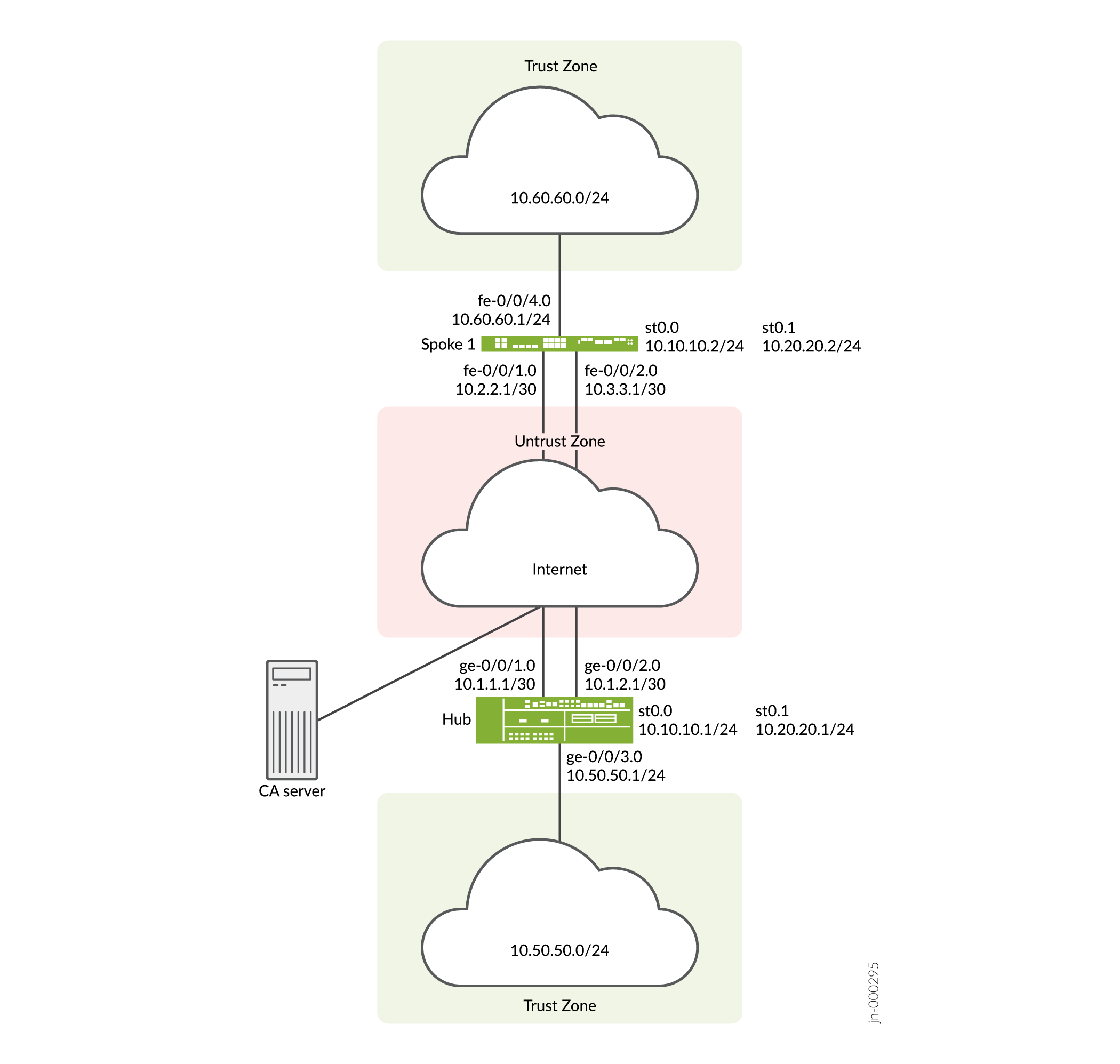
In this example, two IPsec VPN tunnels are established between the hub and spoke 1. Routing information is exchanged through iBGP sessions in each tunnel. The longest prefix match for the route to 10.60.60.0/24 is through the st0.0 interface on the hub. Thus, the primary tunnel for the route is through the st0.0 interfaces on the hub and spoke 1. The default route is through the backup tunnel on the st0.1 interfaces on the hub and spoke 1.
VPN monitoring checks the status of the tunnels. If there is a problem with the primary tunnel (for example, the remote tunnel gateway is not reachable), the tunnel status changes to down and data destined for 10.60.60.0/24 is rerouted through the backup tunnel.
Configuration
To configure AutoVPN, perform these tasks:
The first section describes how to obtain CA and local certificates online using the Simple Certificate Enrollment Protocol (SCEP) on the hub and spoke devices.
Enroll Device Certificates with SCEP
Step-by-Step Procedure
To enroll digital certificates with SCEP on the hub:
-
Configure the CA.
[edit] user@host# set security pki ca-profile ca-profile1 ca-identity ca-profile1 user@host# set security pki ca-profile ca-profile1 enrollment url http://pc4/certsrv/mscep/mscep.dll user@host# set security pki ca-profile ca-profile1 revocation-check disable user@host# commit
-
Enroll the CA certificate.
user@host> request security pki ca-certificate enroll ca-profile ca-profile1
Type yes at the prompt to load the CA certificate.
-
Generate a key pair for each certificate.
user@host> request security pki generate-key-pair certificate-id Local1 user@host> request security pki generate-key-pair certificate-id Local2
-
Enroll the local certificates.
user@host> request security pki local-certificate enroll ca-profile ca-profile1 certificate-id Local1 domain-name example.net email hub@example.net ip-address 10.1.1.1 subject DC=example.net,CN=hub,OU=SLT,O=example,L=Bengaluru,ST=KA,C=IN challenge-password <password> user@host> request security pki local-certificate enroll ca-profile ca-profile1 certificate-id Local2 domain-name example.net email hub_backup@example.net ip-address 10.1.2.1 subject DC=example.net,CN=hub_backup,OU=SBU,O=example,L=Bengaluru,ST=KA,C=IN challenge-password <password>
-
Verify the local certificates.
user@host> show security pki local-certificate certificate-id Local1 detail Certificate identifier: Local1 Certificate version: 3 Serial number: 40a6d5f300000000258d Issuer: Common name: CASERVER1, Domain component: net, Domain component: internal Subject: Organization: example, Organizational unit: SLT, Country: IN, State: KA, Locality: Bengaluru, Common name: hub, Domain component: example.net Subject string: C=IN, DC=example.net, ST=KA, L=Bengaluru, O=example, OU=SLT, CN=hub Alternate subject: "hub@example.net", example.net, 10.1.1.1 Validity: Not before: 11- 6-2012 09:39 Not after: 11- 6-2013 09:49 Public key algorithm: rsaEncryption(1024 bits) 30:81:89:02:81:81:00:c9:c9:cc:30:b6:7a:86:12:89:b5:18:b3:76 01:2d:cc:65:a8:a8:42:78:cd:d0:9a:a2:c0:aa:c4:bd:da:af:88:f3 2a:78:1f:0a:58:e6:11:2c:81:8f:0e:7c:de:86:fc:48:4c:28:5b:8b 34:91:ff:2e:91:e7:b5:bd:79:12:de:39:46:d9:fb:5c:91:41:d1:da 90:f5:09:00:9b:90:07:9d:50:92:7d:ff:fb:3f:3c:bc:34:e7:e3:c8 ea:cb:99:18:b4:b6:1d:a8:99:d3:36:b9:1b:36:ef:3e:a1:fd:48:82 6a:da:22:07:da:e0:d2:55:ef:57:be:09:7a:0e:17:02:03:01:00:01 Signature algorithm: sha1WithRSAEncryption Distribution CRL: http://ca-server1/CertEnroll/CASERVER1.crl file://\\ca-server1\CertEnroll\CASERVER1.crl Fingerprint: e1:f7:a1:a6:1e:c3:97:69:a5:07:9b:09:14:1a:c7:ae:09:f1:f6:35 (sha1) a0:02:fa:8d:5c:63:e5:6d:f7:f4:78:56:ac:4e:b2:c4 (md5) Auto-re-enrollment: Status: Disabled Next trigger time: Timer not starteduser@host> show security pki local-certificate certificate-id Local2 detail Certificate identifier: Local2 Certificate version: 3 Serial number: 505efdf900000000259a Issuer: Common name: CASERVER1, Domain component: net, Domain component: internal Subject: Organization: example, Organizational unit: SBU, Country: IN, State: KA, Locality: Bengaluru, Common name: hub_backup, Domain component: example.net Subject string: C=IN, DC=example.net, ST=KA, L=Bengaluru, O=example, OU=SBU, CN=hub_backup Alternate subject: "hub_backup@example.net", example.net, 10.1.2.1 Validity: Not before: 11- 9-2012 10:55 Not after: 11- 9-2013 11:05 Public key algorithm: rsaEncryption(1024 bits) 30:81:89:02:81:81:00:d5:44:08:96:f6:77:05:e6:91:50:8a:8a:2a 4e:95:43:1e:88:ea:43:7c:c5:ac:88:d7:a0:8d:b5:d9:3f:41:db:db 44:34:1f:56:a5:38:4b:b2:c5:85:f9:f1:bf:b2:7b:d4:b2:af:98:a0 95:50:02:ad:f5:dd:4d:dc:67:85:dd:84:09:df:9c:68:a5:58:65:e7 2c:72:cc:47:4b:d0:cc:4a:28:ca:09:db:ad:6e:5a:13:6c:e6:cc:f0 29:ed:2b:2d:d1:38:38:bc:68:84:de:ae:86:39:c9:dd:06:d5:36:f0 e6:2a:7b:46:4c:cd:a5:24:1c:e0:92:8d:ad:35:29:02:03:01:00:01 Signature algorithm: sha1WithRSAEncryption Distribution CRL: http://ca-server1/CertEnroll/CASERVER1.crl file://\\ca-server1\CertEnroll\CASERVER1.crl Fingerprint: 98:96:2f:ff:ca:af:33:ee:d7:4c:c8:4f:f7:71:53:c0:5d:5f:c5:59 (sha1) c9:87:e3:a4:5c:47:b5:aa:90:22:e3:06:b2:0b:e1:ea (md5) Auto-re-enrollment: Status: Disabled Next trigger time: Timer not started
Step-by-Step Procedure
To enroll digital certificates with SCEP on spoke 1:
-
Configure the CA.
[edit] user@host# set security pki ca-profile ca-profile1 ca-identity ca-profile1 user@host# set security pki ca-profile ca-profile1 enrollment url http://pc4/certsrv/mscep/mscep.dll user@host# set security pki ca-profile ca-profile1 revocation-check disable user@host# commit
-
Enroll the CA certificate.
user@host> request security pki ca-certificate enroll ca-profile ca-profile1
Type yes at the prompt to load the CA certificate.
-
Generate a key pair for each certificate.
user@host> request security pki generate-key-pair certificate-id Local1 user@host> request security pki generate-key-pair certificate-id Local2
-
Enroll the local certificates.
user@host> request security pki local-certificate enroll ca-profile ca-profile1 certificate-id Local1 domain-name example.net email spoke1@example.net ip-address 10.2.2.1 subject DC=example.net,CN=spoke1,OU=SLT,O=example,L=Mysore,ST=KA,C=IN challenge-password <password> user@host> request security pki local-certificate enroll ca-profile ca-profile1 certificate-id Local2 domain-name example.net email spoke1_backup@example.net ip-address 10.3.3.1 subject DC=example.net,CN=spoke1_backup,OU=SBU,O=example,L=Mysore,ST=KA,C=IN challenge-password <password>
-
Verify the local certificates.
user@host> show security pki local-certificate certificate-id Local1 detail Certificate identifier: Local1 Certificate version: 3 Serial number: 40a7975f00000000258e Issuer: Common name: CASERVER1, Domain component: net, Domain component: internal Subject: Organization: example, Organizational unit: SLT, Country: IN, State: KA, Locality: Mysore, Common name: spoke1, Domain component: example.net Subject string: C=IN, DC=example.net, ST=KA, L=Mysore, O=example, OU=SLT, CN=spoke1 Alternate subject: "spoke1@example.net", example.net, 10.2.2.1 Validity: Not before: 11- 6-2012 09:40 Not after: 11- 6-2013 09:50 Public key algorithm: rsaEncryption(1024 bits) 30:81:89:02:81:81:00:d8:45:09:77:cd:36:9a:6f:58:44:18:91:db b0:c7:8a:ee:c8:d7:a6:d2:e2:e7:20:46:2b:26:1a:92:e2:4e:8a:ce c9:25:d9:74:a2:81:ad:ea:e0:38:a0:2f:2d:ab:a6:58:ac:88:35:f4 90:01:08:33:33:75:2c:44:26:f8:25:18:97:96:e4:28:de:3b:35:f2 4a:f5:92:b7:57:ae:73:4f:8e:56:71:ab:81:54:1d:75:88:77:13:64 1b:6b:01:96:15:0a:1c:54:e3:db:f8:ec:ec:27:5b:86:39:c1:09:a1 e4:24:1a:19:0d:14:2c:4b:94:a4:04:91:3f:cb:ef:02:03:01:00:01 Signature algorithm: sha1WithRSAEncryption Distribution CRL: http://ca-server1/CertEnroll/CASERVER1.crl file://\\ca-server1\CertEnroll\CASERVER1.crl Fingerprint: b6:24:2a:0e:96:5d:8c:4a:11:f3:5a:24:89:7c:df:ea:d5:c0:80:56 (sha1) 31:58:7f:15:bb:d4:66:b8:76:1a:42:4a:8a:16:b3:a9 (md5) Auto-re-enrollment: Status: Disabled Next trigger time: Timer not started user@host> show security pki local-certificate certificate-id Local2 detail Certificate identifier: Local2 Certificate version: 3 Serial number: 506c3d0600000000259b Issuer: Common name: CASERVER1, Domain component: net, Domain component: internal Subject: Organization: example, Organizational unit: SBU, Country: IN, State: KA, Locality: Mysore, Common name: spoke1_backup, Domain component: example.net Subject string: C=IN, DC=example.net, ST=KA, L=Mysore, O=example, OU=SBU, CN=spoke1_backup Alternate subject: "spoke1_backup@example.net", example.net, 10.3.3.1 Validity: Not before: 11- 9-2012 11:09 Not after: 11- 9-2013 11:19 Public key algorithm: rsaEncryption(1024 bits) 30:81:89:02:81:81:00:a7:02:b5:e2:cd:79:24:f8:97:a3:8d:4d:27 8c:2b:dd:f1:57:72:4d:2b:6d:d5:95:0d:9c:1b:5c:e2:a4:b0:84:2e 31:82:3c:91:08:a2:58:b9:30:4c:5f:a3:6b:e6:2b:9c:b1:42:dd:1c cd:a2:7a:84:ea:7b:a6:b7:9a:13:33:c6:27:2b:79:2a:b1:0c:fe:08 4c:a7:35:fc:da:4f:df:1f:cf:f4:ba:bc:5a:05:06:63:92:41:b4:f2 54:00:3f:ef:ff:41:e6:ca:74:10:56:f7:2b:5f:d3:1a:33:7e:49:74 1c:42:cf:c2:23:ea:4b:8f:50:2c:eb:1c:a6:37:89:02:03:01:00:01 Signature algorithm: sha1WithRSAEncryption Distribution CRL: http://ca-server1/CertEnroll/CASERVER1.crl file://\\ca-server1\CertEnroll\CASERVER1.crl Fingerprint: d6:7f:52:a3:b6:f8:ae:cb:70:3f:a9:79:ea:8a:da:9e:ba:83:e4:5f (sha1) 76:0b:72:73:cf:51:ee:58:81:2d:f7:b4:e2:5c:f4:5c (md5) Auto-re-enrollment: Status: Disabled Next trigger time: Timer not startedThe organizational unit (OU) shown in the subject field is
SLTfor Local1 andSBUfor Local2. The IKE configurations on the hub includeOU=SLTandOU=SBUto identify the spoke.
Configuring the Hub
CLI Quick Configuration
To quickly configure this example, copy the following commands, paste them
into a text file, remove any line breaks, change any details necessary to
match your network configuration, copy and paste the commands into the CLI
at the [edit] hierarchy level, and then enter
commit from configuration mode.
set interfaces ge-0/0/1 unit 0 family inet address 10.1.1.1/30 set interfaces ge-0/0/2 unit 0 family inet address 10.1.2.1/30 set interfaces ge-0/0/3 unit 0 family inet address 10.50.50.1/24 set interfaces st0 unit 0 multipoint set interfaces st0 unit 0 family inet address 10.10.10.1/24 set interfaces st0 unit 1 multipoint set interfaces st0 unit 1 family inet address 10.20.20.1/24 set policy-options policy-statement lan_nw from interface ge-0/0/3.0 set policy-options policy-statement lan_nw then accept set protocols bgp group ibgp-1 type internal set protocols bgp group ibgp-1 local-address 10.10.10.1 set protocols bgp group ibgp-1 export lan_nw set protocols bgp group ibgp-1 cluster 10.2.3.4 set protocols bgp group ibgp-1 allow 10.10.10.0/24 set protocols bgp group ibgp-2 type internal set protocols bgp group ibgp-2 local-address 10.20.20.1 set protocols bgp group ibgp-2 export lan_nw set protocols bgp group ibgp-2 cluster 10.2.3.5 set protocols bgp group ibgp-2 allow 10.20.20.0/24 set routing-options static route 10.2.2.0/30 next-hop 10.1.1.2 set routing-options static route 10.3.3.0/30 next-hop 10.1.2.2 set routing-options autonomous-system 65010 set security ike proposal ike-proposal authentication-method rsa-signatures set security ike proposal ike-proposal dh-group group2 set security ike proposal ike-proposal authentication-algorithm sha1 set security ike proposal ike-proposal encryption-algorithm aes-128-cbc set security ike policy ike-policy-1 mode main set security ike policy ike-policy-1 proposals ike-proposal set security ike policy ike-policy-1 certificate local-certificate Local1 set security ike policy ike-policy-2 mode main set security ike policy ike-policy-2 proposals ike-proposal set security ike policy ike-policy-2 certificate local-certificate Local2 set security ike gateway hub-to-spoke-gw-1 ike-policy ike-policy-1 set security ike gateway hub-to-spoke-gw-1 dynamic distinguished-name wildcard OU=SLT set security ike gateway hub-to-spoke-gw-1 dynamic ike-user-type group-ike-id set security ike gateway hub-to-spoke-gw-1 local-identity distinguished-name set security ike gateway hub-to-spoke-gw-1 external-interface ge-0/0/1.0 set security ike gateway hub-to-spoke-gw-2 ike-policy ike-policy-2 set security ike gateway hub-to-spoke-gw-2 dynamic distinguished-name wildcard OU=SBU set security ike gateway hub-to-spoke-gw-2 dynamic ike-user-type group-ike-id set security ike gateway hub-to-spoke-gw-2 local-identity distinguished-name set security ike gateway hub-to-spoke-gw-2 external-interface ge-0/0/2.0 set security ipsec vpn-monitor-options interval 5 set security ipsec vpn-monitor-options threshold 2 set security ipsec proposal ipsec-proposal protocol esp set security ipsec proposal ipsec-proposal authentication-algorithm hmac-md5-96 set security ipsec proposal ipsec-proposal encryption-algorithm des-cbc set security ipsec policy vpn-policy perfect-forward-secrecy keys group14 set security ipsec policy vpn-policy proposals ipsec-proposal set security ipsec vpn hub-to-spoke-vpn-1 bind-interface st0.0 set security ipsec vpn hub-to-spoke-vpn-1 vpn-monitor source-interface ge-0/0/1.0 set security ipsec vpn hub-to-spoke-vpn-1 ike gateway hub-to-spoke-gw-1 set security ipsec vpn hub-to-spoke-vpn-1 ike ipsec-policy vpn-policy set security ipsec vpn hub-to-spoke-vpn-2 bind-interface st0.1 set security ipsec vpn hub-to-spoke-vpn-2 vpn-monitor source-interface ge-0/0/2.0 set security ipsec vpn hub-to-spoke-vpn-2 ike gateway hub-to-spoke-gw-2 set security ipsec vpn hub-to-spoke-vpn-2 ike ipsec-policy vpn-policy set security zones security-zone untrust host-inbound-traffic system-services all set security zones security-zone untrust host-inbound-traffic protocols all set security zones security-zone untrust interfaces st0.0 set security zones security-zone untrust interfaces ge-0/0/1.0 set security zones security-zone untrust interfaces ge-0/0/2.0 set security zones security-zone untrust interfaces st0.1 set security zones security-zone trust host-inbound-traffic system-services all set security zones security-zone trust host-inbound-traffic protocols all set security zones security-zone trust interfaces ge-0/0/3.0 set security policies default-policy permit-all set security pki ca-profile ca-profile1 ca-identity ca-profile1 set security pki ca-profile ca-profile1 enrollment url http://pc4/certsrv/mscep/mscep.dll set security pki ca-profile ca-profile1 revocation-check disable
Step-by-Step Procedure
The following example requires you to navigate various levels in the configuration hierarchy.
To configure the hub:
-
Configure the interfaces.
[edit interfaces] user@host# set ge-0/0/1 unit 0 family inet address 10.1.1.1/30 user@host# set ge-0/0/2 unit 0 family inet address 10.1.2.1/30 user@host# set ge-0/0/3 unit 0 family inet address 10.50.50.1/24 user@host# set st0 unit 0 multipoint user@host# set st0 unit 0 family inet address 10.10.10.1/24 user@host# set st0 unit 1 multipoint user@host# set st0 unit 1 family inet address 10.20.20.1/24
-
Configure routing protocol.
[edit policy-options] user@host# set policy-statement lan_nw from interface ge-0/0/3.0 user@host# set policy-statement lan_nw then accept [edit protocols bgp] user@host# set group ibgp-1 type internal user@host# set group ibgp-1 local-address 10.10.10.1 user@host# set group ibgp-1 export lan_nw user@host# set group ibgp-1 cluster 10.2.3.4 user@host# set group ibgp-1 allow 10.10.10.0/24 user@host# set group ibgp-2 type internal user@host# set group ibgp-2 local-address 10.20.20.1 user@host# set group ibgp-2 export lan_nw user@host# set group ibgp-2 cluster 10.2.3.5 user@host# set group ibgp-2 allow 10.20.20.0/24 [edit routing-options] user@host# set static route 10.2.2.0/30 next-hop 10.1.1.2 user@host# set static route 10.3.3.0/30 next-hop 10.1.2.2 user@host# set autonomous-system 65010
-
Configure Phase 1 options.
[edit security ike proposal ike-proposal] user@host# set authentication-method rsa-signatures user@host# set dh-group group2 user@host# set authentication-algorithm sha1 user@host# set encryption-algorithm aes-128-cbc [edit security ike policy ike-policy-1] user@host# set mode main user@host# set proposals ike-proposal user@host# set certificate local-certificate Local1 [edit security ike policy ike-policy-2] user@host# set mode main user@host# set proposals ike-proposal user@host# set certificate local-certificate Local2 [edit security ike gateway hub-to-spoke-gw-1] user@host# set ike-policy ike-policy-1 user@host# set dynamic distinguished-name wildcard OU=SLT user@host# set dynamic ike-user-type group-ike-id user@host# set local-identity distinguished-name user@host# set external-interface ge-0/0/1.0 [edit security ike gateway hub-to-spoke-gw-2] user@host# set ike-policy ike-policy-2 user@host# set dynamic distinguished-name wildcard OU=SBU user@host# set dynamic ike-user-type group-ike-id user@host# set local-identity distinguished-name user@host# set external-interface ge-0/0/2.0
-
Configure Phase 2 options.
[edit security ipsec vpn-monitor] user@host# set options interval 5 user@host# set options threshold 2 [edit security ipsec proposal ipsec-proposal] user@host# set protocol esp user@host# set authentication-algorithm hmac-md5-96 user@host# set encryption-algorithm des-cbc [edit security ipsec policy vpn-policy] user@host# set perfect-forward-secrecy keys group14 user@host# set proposals ipsec-proposal [edit security ipsec vpn hub-to-spoke-vpn-1] user@host# set bind-interface st0.0 user@host# set vpn-monitor source-interface ge-0/0/1.0 user@host# set ike gateway hub-to-spoke-gw-1 user@host# set ike ipsec-policy vpn-policy [edit security ipsec vpn hub-to-spoke-vpn-2] user@host# set bind-interface st0.1 user@host# set vpn-monitor source-interface ge-0/0/2.0 user@host# set ike gateway hub-to-spoke-gw-2 user@host# set ike ipsec-policy vpn-policy
-
Configure zones.
[edit security zones security-zone untrust] user@host# set host-inbound-traffic system-services all user@host# set host-inbound-traffic protocols all user@host# set interfaces st0.0 user@host# set interfaces ge-0/0/1.0 user@host# set interfaces ge-0/0/2.0 user@host# set interfaces st0.1 [edit security zones security-zone trust] user@host# set host-inbound-traffic system-services all user@host# set host-inbound-traffic protocols all user@host# set interfaces ge-0/0/3.0
-
Configure the default security policy.
[edit security policies] user@host# set default-policy permit-all
-
Configure the CA profile.
[edit security pki] user@host# set ca-profile ca-profile1 ca-identity ca-profile1 user@host# set ca-profile ca-profile1 enrollment url http://pc4/certsrv/mscep/mscep.dll user@host# set ca-profile ca-profile1 revocation-check disable
Results
From configuration mode, confirm your configuration by entering the
show interfaces, show policy-options,
show protocols, show routing-options,
show security ike, show security
ipsec, show security zones, show security
policies, and show security pki commands. If
the output does not display the intended configuration, repeat the
configuration instructions in this example to correct it.
[edit]
user@host# show interfaces
ge-0/0/1 {
unit 0 {
family inet {
address 10.1.1.1/30;
}
}
}
ge-0/0/2 {
unit 0 {
family inet {
address 10.1.2.1/30;
}
}
}
ge-0/0/3 {
unit 0 {
family inet {
address 10.50.50.1/24;
}
}
}
st0 {
unit 0 {
multipoint;
family inet {
address 10.10.10.1/24;
}
}
unit 1 {
multipoint;
family inet {
address 10.20.20.1/24;
}
}
}
[edit]
user@host# show policy-options
policy-statement lan_nw {
from interface ge-0/0/3.0;
then accept;
}
[edit]
user@host# show protocols
bgp {
group ibgp-1 {
type internal;
local-address 10.10.10.1;
export lan_nw;
cluster 10.2.3.4;
allow 10.10.10.0/24;
}
group ibgp-2 {
type internal;
local-address 10.20.20.1;
export lan_nw;
cluster 10.2.3.5;
allow 10.20.20.0/24;
}
}
[edit]
user@host# show routing-options
static {
route 10.2.2.0/30 next-hop 10.1.1.2;
route 10.3.3.0/30 next-hop 10.1.2.2;
}
autonomous-system 65010;
[edit]
user@host# show security ike
proposal ike-proposal {
authentication-method rsa-signatures;
dh-group group2;
authentication-algorithm sha1;
encryption-algorithm aes-128-cbc;
}
policy ike-policy-1 {
mode main;
proposals ike-proposal;
certificate {
local-certificate Local1;
}
}
policy ike-policy-2 {
mode main;
proposals ike-proposal;
certificate {
local-certificate Local2;
}
}
gateway hub-to-spoke-gw-1 {
ike-policy ike-policy-1;
dynamic {
distinguished-name {
wildcard OU=SLT;
}
ike-user-type group-ike-id;
}
local-identity distinguished-name;
external-interface ge-0/0/1.0;
}
gateway hub-to-spoke-gw-2 {
ike-policy ike-policy-2;
dynamic {
distinguished-name {
wildcard OU=SBU;
}
ike-user-type group-ike-id;
}
local-identity distinguished-name;
external-interface ge-0/0/2.0;
}
[edit]
user@host# show security ipsec
vpn-monitor-options {
interval 5;
threshold 2;
}
proposal ipsec-proposal {
protocol esp;
authentication-algorithm hmac-md5-96;
encryption-algorithm des-cbc;
}
policy vpn-policy {
perfect-forward-secrecy {
keys group14;
}
proposals ipsec-proposal;
}
vpn hub-to-spoke-vpn-1 {
bind-interface st0.0;
vpn-monitor {
source-interface ge-0/0/1.0;
}
ike {
gateway hub-to-spoke-gw-1;
ipsec-policy vpn-policy;
}
}
vpn hub-to-spoke-vpn-2 {
bind-interface st0.1;
vpn-monitor {
source-interface ge-0/0/2.0;
}
ike {
gateway hub-to-spoke-gw-2;
ipsec-policy vpn-policy;
}
}
[edit]
user@host# show security zones
security-zone untrust {
host-inbound-traffic {
system-services {
all;
}
protocols {
all;
}
}
interfaces {
st0.0;
ge-0/0/1.0;
ge-0/0/2.0;
st0.1;
}
}
security-zone trust {
host-inbound-traffic {
system-services {
all;
}
protocols {
all;
}
}
interfaces {
ge-0/0/3.0;
}
}
[edit]
user@host# show security policies
default-policy {
permit-all;
}
[edit]
user@host# show security pki
ca-profile ca-profile1 {
ca-identity ca-profile1;
enrollment {
url http://pc4/certsrv/mscep/mscep.dll;
}
revocation-check {
disable;
}
}
If you are done configuring the device, enter commit from
configuration mode.
Configuring Spoke 1
CLI Quick Configuration
To quickly configure this example, copy the following commands, paste them
into a text file, remove any line breaks, change any details necessary to
match your network configuration, copy and paste the commands into the CLI
at the [edit] hierarchy level, and then enter
commit from configuration mode.
set interfaces fe-0/0/1 unit 0 family inet address 10.2.2.1/30 set interfaces fe-0/0/2 unit 0 family inet address 10.3.3.1/30 set interfaces fe-0/0/4 unit 0 family inet address 10.60.60.1/24 set interfaces st0 unit 0 family inet address 10.10.10.2/24 set interfaces st0 unit 1 family inet address 10.20.20.2/24 set policy-options policy-statement default_route from protocol static set policy-options policy-statement default_route from route-filter 0.0.0.0/0 exact set policy-options policy-statement default_route then accept set policy-options policy-statement lan_nw from interface fe-0/0/4.0 set policy-options policy-statement lan_nw then accept set protocols bgp group ibgp-1 type internal set protocols bgp group ibgp-1 local-address 10.10.10.2 set protocols bgp group ibgp-1 export lan_nw set protocols bgp group ibgp-1 neighbor 10.10.10.1 set protocols bgp group ibgp-2 type internal set protocols bgp group ibgp-2 local-address 10.20.20.2 set protocols bgp group ibgp-2 export default_route set protocols bgp group ibgp-2 neighbor 10.20.20.1 set routing-options static route 10.1.1.0/30 next-hop 10.2.2.2 set routing-options static route 10.1.2.0/30 next-hop 10.3.3.2 set routing-options static route 0.0.0.0/0 next-hop st0.1 set routing-options autonomous-system 65010 set security ike proposal ike-proposal authentication-method rsa-signatures set security ike proposal ike-proposal dh-group group2 set security ike proposal ike-proposal authentication-algorithm sha1 set security ike proposal ike-proposal encryption-algorithm aes-128-cbc set security ike policy ike-policy-1 mode main set security ike policy ike-policy-1 proposals ike-proposal set security ike policy ike-policy-1 certificate local-certificate Local1 set security ike policy ike-policy-2 mode main set security ike policy ike-policy-2 proposals ike-proposal set security ike policy ike-policy-2 certificate local-certificate Local2 set security ike gateway spoke-to-hub-gw-1 ike-policy ike-policy-1 set security ike gateway spoke-to-hub-gw-1 address 10.1.1.1 set security ike gateway spoke-to-hub-gw-1 local-identity distinguished-name set security ike gateway spoke-to-hub-gw-1 remote-identity distinguished-name set security ike gateway spoke-to-hub-gw-1 external-interface fe-0/0/1.0 set security ike gateway spoke-to-hub-gw-2 ike-policy ike-policy-2 set security ike gateway spoke-to-hub-gw-2 address 10.1.2.1 set security ike gateway spoke-to-hub-gw-2 local-identity distinguished-name set security ike gateway spoke-to-hub-gw-2 remote-identity distinguished-name set security ike gateway spoke-to-hub-gw-2 external-interface fe-0/0/2.0 set security ipsec vpn-monitor-options interval 5 set security ipsec vpn-monitor-options threshold 2 set security ipsec proposal ipsec-proposal protocol esp set security ipsec proposal ipsec-proposal authentication-algorithm hmac-md5-96 set security ipsec proposal ipsec-proposal encryption-algorithm des-cbc set security ipsec policy vpn-policy perfect-forward-secrecy keys group14 set security ipsec policy vpn-policy proposals ipsec-proposal set security ipsec vpn spoke-to-hub-1 bind-interface st0.0 set security ipsec vpn spoke-to-hub-1 vpn-monitor destination-ip 10.1.1.1 set security ipsec vpn spoke-to-hub-1 ike gateway spoke-to-hub-gw-1 set security ipsec vpn spoke-to-hub-1 ike ipsec-policy vpn-policy set security ipsec vpn spoke-to-hub-1 establish-tunnels immediately set security ipsec vpn spoke-to-hub-2 bind-interface st0.1 set security ipsec vpn spoke-to-hub-2 vpn-monitor destination-ip 10.1.2.1 set security ipsec vpn spoke-to-hub-2 ike gateway spoke-to-hub-gw-2 set security ipsec vpn spoke-to-hub-2 ike ipsec-policy vpn-policy set security ipsec vpn spoke-to-hub-2 establish-tunnels immediately set security zones security-zone untrust host-inbound-traffic system-services all set security zones security-zone untrust host-inbound-traffic protocols all set security zones security-zone untrust interfaces fe-0/0/1.0 set security zones security-zone untrust interfaces st0.0 set security zones security-zone untrust interfaces fe-0/0/2.0 set security zones security-zone untrust interfaces st0.1 set security zones security-zone trust host-inbound-traffic system-services all set security zones security-zone trust host-inbound-traffic protocols all set security zones security-zone trust interfaces fe-0/0/4.0 set security policies default-policy permit-all set security pki ca-profile ca-profile1 ca-identity ca-profile1 set security pki ca-profile ca-profile1 enrollment url http://pc4/certsrv/mscep/mscep.dll set security pki ca-profile ca-profile1 revocation-check disable
Step-by-Step Procedure
The following example requires you to navigate various levels in the configuration hierarchy.
To configure spoke 1:
-
Configure interfaces.
[edit interfaces] user@host# set fe-0/0/1 unit 0 family inet address 10.2.2.1/30 user@host# set fe-0/0/2 unit 0 family inet address 10.3.3.1/30 user@host# set fe-0/0/4 unit 0 family inet address 10.60.60.1/24 user@host# set st0 unit 0 family inet address 10.10.10.2/24 user@host# set st0 unit 1 family inet address 10.20.20.2/24
-
Configure routing protocol.
[edit policy-options] user@host# set policy-statement default_route from protocol static user@host# set policy-statement default_route from route-filter 0.0.0.0/0 exact user@host# set policy-statement default_route then accept user@host# set policy-statement lan_nw from interface fe-0/0/4.0 user@host# set policy-statement lan_nw then accept [edit protocols bgp] user@host# set group ibgp-1 type internal user@host# set group ibgp-1 local-address 10.10.10.2 user@host# set group ibgp-1 export lan_nw user@host# set group ibgp-1 neighbor 10.10.10.1 user@host# set group ibgp-2 type internal user@host# set group ibgp-2 local-address 10.20.20.2 user@host# set group ibgp-2 export default_route user@host# set group ibgp-2 neighbor 10.20.20.1 [edit routing-options] user@host# set static route 10.1.1.0/30 next-hop 10.2.2.2 user@host# set static route 10.1.2.0/30 next-hop 10.3.3.2 user@host# set static route 0.0.0.0/0 next-hop st0.1 user@host# set autonomous-system 65010
-
Configure Phase 1 options.
[edit security ike proposal ike-proposal] user@host# set authentication-method rsa-signatures user@host# set dh-group group2 user@host# set authentication-algorithm sha1 user@host# set encryption-algorithm aes-128-cbc [edit security ike policy ike-policy-1] user@host# set mode main user@host# set proposals ike-proposal user@host# set certificate local-certificate Local1 [edit security ike policy ike-policy-2] user@host# set mode main user@host# set proposals ike-proposal user@host# set certificate local-certificate Local2 [edit security ike gateway spoke-to-hub-gw-1] user@host# set ike-policy ike-policy-1 user@host# set address 10.1.1.1 user@host# set local-identity distinguished-name user@host# set remote-identity distinguished-name user@host# set external-interface fe-0/0/1.0 [edit security ike gateway spoke-to-hub-gw-2] user@host# set ike-policy ike-policy-2 user@host# set address 10.1.2.1 user@host# set local-identity distinguished-name user@host# set remote-identity distinguished-name user@host# set external-interface fe-0/0/2.0
-
Configure Phase 2 options.
[edit security ipsec vpn-monitor] user@host# set options interval 5 user@host# set options threshold 2 [edit security ipsec proposal ipsec-proposal] user@host# set protocol esp user@host# set authentication-algorithm hmac-md5-96 user@host# set encryption-algorithm des-cbc [edit security ipsec policy vpn-policy] user@host# set perfect-forward-secrecy keys group14 user@host# set proposals ipsec-proposal [edit security ipsec vpn spoke-to-hub-1] user@host# set bind-interface st0.0 user@host# set vpn-monitor destination-ip 10.1.1.1 user@host# set ike gateway spoke-to-hub-gw-1 user@host# set ike ipsec-policy vpn-policy user@host# set establish-tunnels immediately [edit security ipsec vpn spoke-to-hub-2] user@host# set bind-interface st0.1 user@host# set vpn-monitor destination-ip 10.1.2.1 user@host# set ike gateway spoke-to-hub-gw-2 user@host# set ike ipsec-policy vpn-policy user@host# set establish-tunnels immediately
-
Configure zones.
[edit security zones security-zone untrust] user@host# set host-inbound-traffic system-services all user@host# set host-inbound-traffic protocols all user@host# set interfaces fe-0/0/1.0 user@host# set interfaces st0.0 user@host# set interfaces fe-0/0/2.0 user@host# set interfaces st0.1 [edit security zones security-zone trust] user@host# set host-inbound-traffic system-services all user@host# set host-inbound-traffic protocols all user@host# set interfaces fe-0/0/4.0
-
Configure the default security policy.
[edit security policies] user@host# set default-policy permit-all
-
Configure the CA profile.
[edit security pki] user@host# set ca-profile ca-profile1 ca-identity ca-profile1 user@host# set ca-profile ca-profile1 enrollment url http://pc4/certsrv/mscep/mscep.dll user@host# set ca-profile ca-profile1 revocation-check disable
Results
From configuration mode, confirm your configuration by entering the
show interfaces, show policy-options,
show protocols, show routing-options,
show security ike, show security
ipsec, show security zones, show security
policies, and show security pki commands. If
the output does not display the intended configuration, repeat the
configuration instructions in this example to correct it.
[edit]
user@host# show interfaces
fe-0/0/1 {
unit 0 {
family inet {
address 10.2.2.1/30;
}
}
}
fe-0/0/2 {
unit 0 {
family inet {
address 10.3.3.1/30;
}
}
}
fe-0/0/4 {
unit 0 {
family inet {
address 10.60.60.1/24;
}
}
}
st0 {
unit 0 {
family inet {
address 10.10.10.2/24;
}
}
unit 1 {
family inet {
address 10.20.20.2/24;
}
}
}
[edit]
user@host# show policy-options
policy-statement default_route {
from {
protocol static;
route-filter 0.0.0.0/0 exact;
}
then accept;
}
policy-statement lan_nw {
from interface fe-0/0/4.0;
then accept;
}
[edit]
user@host# show protocols
bgp {
group ibgp-1 {
type internal;
local-address 10.10.10.2;
export lan_nw;
neighbor 10.10.10.1;
}
group ibgp-2 {
type internal;
local-address 10.20.20.2;
export default_route;
neighbor 10.20.20.1;
}
}
[edit]
user@host# show routing-options
static {
route 10.1.1.0/30 next-hop 10.2.2.2;
route 10.1.2.0/30 next-hop 10.3.3.2;
route 0.0.0.0/0 next-hop st0.1;
}
autonomous-system 65010;
[edit]
user@host# show security ike
proposal ike-proposal {
authentication-method rsa-signatures;
dh-group group2;
authentication-algorithm sha1;
encryption-algorithm aes-128-cbc;
}
policy ike-policy-1 {
mode main;
proposals ike-proposal;
certificate {
local-certificate Local1;
}
}
policy ike-policy-2 {
mode main;
proposals ike-proposal;
certificate {
local-certificate Local2;
}
}
gateway spoke-to-hub-gw-1 {
ike-policy ike-policy-1;
address 10.1.1.1;
local-identity distinguished-name;
remote-identity distinguished-name;
external-interface fe-0/0/1.0;
}
gateway spoke-to-hub-gw-2 {
ike-policy ike-policy-2;
address 10.1.2.1;
local-identity distinguished-name;
remote-identity distinguished-name;
external-interface fe-0/0/2.0;
}
[edit]
user@host# show security ipsec
vpn-monitor-options {
interval 5;
threshold 2;
}
proposal ipsec-proposal {
protocol esp;
authentication-algorithm hmac-md5-96;
encryption-algorithm des-cbc;
}
policy vpn-policy {
perfect-forward-secrecy {
keys group14;
}
proposals ipsec-proposal;
}
vpn spoke-to-hub-1 {
bind-interface st0.0;
vpn-monitor {
destination-ip 10.1.1.1;
}
ike {
gateway spoke-to-hub-gw-1;
ipsec-policy vpn-policy;
}
establish-tunnels immediately;
}
vpn spoke-to-hub-2 {
bind-interface st0.1;
vpn-monitor {
destination-ip 10.1.2.1;
}
ike {
gateway spoke-to-hub-gw-2;
ipsec-policy vpn-policy;
}
establish-tunnels immediately;
}
[edit]
user@host# show security zones
security-zone untrust {
host-inbound-traffic {
system-services {
all;
}
protocols {
all;
}
}
interfaces {
fe-0/0/1.0;
st0.0;
fe-0/0/2.0;
st0.1;
}
}
security-zone trust {
host-inbound-traffic {
system-services {
all;
}
protocols {
all;
}
}
interfaces {
fe-0/0/4.0;
}
}
[edit]
user@host# show security policies
default-policy {
permit-all;
}
[edit]
user@host# show security pki
ca-profile ca-profile1 {
ca-identity ca-profile1;
enrollment {
url http://pc4/certsrv/mscep/mscep.dll;
}
revocation-check {
disable;
}
}
If you are done configuring the device, enter commit from
configuration mode.
Verification
Confirm that the configuration is working properly.
- Verifying IKE Phase 1 Status (Both Tunnels Are Up)
- Verifying IPsec Phase 2 Status (Both Tunnels Are Up)
- Verifying IPsec Next-Hop Tunnels (Both Tunnels Are Up)
- Verifying BGP (Both Tunnels Are Up)
- Verifying Learned Routes (Both Tunnels Are Up)
- Verifying IKE Phase 1 Status (Primary Tunnel Is Down)
- Verifying IPsec Phase 2 Status (Primary Tunnel Is Down)
- Verifying IPsec Next-Hop Tunnels (Primary Tunnel Is Down)
- Verifying BGP (Primary Tunnel Is Down)
- Verifying Learned Routes (Primary Tunnel Is Down)
Verifying IKE Phase 1 Status (Both Tunnels Are Up)
Purpose
Verify the IKE Phase 1 status when both IPSec VPN tunnels are up.
Action
From operational mode, enter the show security ike security-associations command.
user@host> show security ike security-associations Index State Initiator cookie Responder cookie Mode Remote Address 3733075 UP d4f51c28c0a82101 05b125993a864d3c Main 10.3.3.1 3733076 UP d53c8a0b7d4c319b c23c5f7a26388247 Main 10.2.2.1
Meaning
The show security ike security-associations command lists
all active IKE Phase 1 SAs. If no SAs are listed, there was a problem with
Phase 1 establishment. Check the IKE policy parameters and external
interface settings in your configuration. Phase 1 proposal parameters must
match on the hub and spoke.
Verifying IPsec Phase 2 Status (Both Tunnels Are Up)
Purpose
Verify the IPsec Phase 2 status when both IPsec VPN tunnels are up.
Action
From operational mode, enter the security ipsec security-associations command.
user@host> security ipsec security-associations Total active tunnels: 2 ID Algorithm SPI Life:sec/kb Mon vsys Port Gateway <268173316 ESP:des/ md5 3cd96946 3555/ unlim U root 500 10.2.2.1 >268173316 ESP:des/ md5 1c09b9b 3555/ unlim U root 500 10.2.2.1 <268173313 ESP:des/ md5 7c6ffca3 3340/ unlim U root 500 10.3.3.1 >268173313 ESP:des/ md5 33bf6f2f 3340/ unlim U root 500 10.3.3.1
Meaning
The show security ipsec security-associations command lists
all active IKE Phase 2 SAs. If no SAs are listed, there was a problem with
Phase 2 establishment. Check the IKE policy parameters and external
interface settings in your configuration. Phase 2 proposal parameters must
match on the hub and spoke.
Verifying IPsec Next-Hop Tunnels (Both Tunnels Are Up)
Purpose
Verify the IPsec next-hop tunnels.
Action
From operational mode, enter the show security ipsec next-hop-tunnels command.
user@host> show security ipsec next-hop-tunnels Next-hop gateway interface IPSec VPN name Flag IKE-ID XAUTH username 10.10.10.2 st0.0 hub-to-spoke-vpn-1 Auto C=IN, DC=example.net, ST=KA, L=Mysore, O=example, OU=SLT, CN=spoke1 10.20.20.2 st0.1 hub-to-spoke-vpn-2 Auto C=IN, DC=example.net, ST=KA, L=Mysore, O=example, OU=SBU, CN=spoke1_backup
Meaning
The next-hop gateways are the IP addresses for the st0
interfaces of the spoke. The next hop should be associated with the correct
IPsec VPN name.
Verifying BGP (Both Tunnels Are Up)
Purpose
Verify that BGP references the IP addresses for the st0
interfaces of the spoke when both IPsec VPN tunnels are up.
Action
From operational mode, enter the show bgp summary command.
user@host> show bgp summary Groups: 2 Peers: 2 Down peers: 0 Unconfigured peers: 2 Table Tot Paths Act Paths Suppressed History Damp State Pending inet.0 2 2 0 0 0 0 Peer AS InPkt OutPkt OutQ Flaps Last Up/Dwn State|#Active/Received/Accepted/Damped... 10.10.10.2 65010 5 6 0 0 54 1/1/1/0 0/0/0/0 10.20.20.2 65010 13 16 0 0 4:29 1/1/1/0 0/0/0/0
Verifying Learned Routes (Both Tunnels Are Up)
Purpose
Verify that routes to the spoke have been learned when both tunnels are up. The route to 10.60.60.0/24 is through the st0.0 interface and the default route is through the st0.1 interface.
Action
From operational mode, enter the show route 10.60.60.0 command.
user@host> show route 10.60.60.0
inet.0: 48 destinations, 48 routes (47 active, 0 holddown, 1 hidden)
+ = Active Route, - = Last Active, * = Both
60.60.60.0/24 *[BGP/170] 00:01:11, localpref 100
AS path: I
> to 10.10.10.2 via st0.0
From operational mode, enter the show route 0.0.0.0 command.
user@host> show route 0.0.0.0
inet.0: 48 destinations, 48 routes (47 active, 0 holddown, 1 hidden)
+ = Active Route, - = Last Active, * = Both
0.0.0.0/0 *[BGP/170] 00:04:55, localpref 100
AS path: I
> to 10.20.20.2 via st0.1
Verifying IKE Phase 1 Status (Primary Tunnel Is Down)
Purpose
Verify the IKE Phase 1 status when the primary tunnel is down.
Action
From operational mode, enter the show security ike security-associations command.
user@host> show security ike security-associations Index State Initiator cookie Responder cookie Mode Remote Address 3733075 UP d4f51c28c0a82101 05b125993a864d3c Main 10.3.3.1 3733076 UP d53c8a0b7d4c319b c23c5f7a26388247 Main 10.2.2.1
Meaning
The show security ike security-associations command lists
all active IKE Phase 1 SAs. If no SAs are listed, there was a problem with
Phase 1 establishment. Check the IKE policy parameters and external
interface settings in your configuration. Phase 1 proposal parameters must
match on the hub and spoke.
Verifying IPsec Phase 2 Status (Primary Tunnel Is Down)
Purpose
Verify the IPsec Phase 2 status when the primary tunnel is down.
Action
From operational mode, enter the security ipsec security-associations command.
user@host> security ipsec security-associations Total active tunnels: 1 ID Algorithm SPI Life:sec/kb Mon vsys Port Gateway <268173313 ESP:des/ md5 7c6ffca3 3156/ unlim U root 500 10.3.3.1 >268173313 ESP:des/ md5 33bf6f2f 3156/ unlim U root 500 10.3.3.1
Meaning
The show security ipsec security-associations command lists
all active IKE Phase 2 SAs. If no SAs are listed, there was a problem with
Phase 2 establishment. Check the IKE policy parameters and external
interface settings in your configuration. Phase 2 proposal parameters must
match on the hub and spoke.
Verifying IPsec Next-Hop Tunnels (Primary Tunnel Is Down)
Purpose
Verify the IPsec next-hop tunnel.
Action
From operational mode, enter the show security ipsec next-hop-tunnels command.
user@host> show security ipsec next-hop-tunnels Next-hop gateway interface IPSec VPN name Flag IKE-ID XAUTH username 10.20.20.2 st0.1 hub-to-spoke-vpn-2 Auto C=IN, DC=example.net, ST=KA, L=Mysore, O=example, OU=SBU, CN=spoke1_backup
Meaning
The next-hop gateways are the IP addresses for the st0
interfaces of the spoke. The next hop should be associated with the correct
IPsec VPN name, in this case the backup VPN tunnel.
Verifying BGP (Primary Tunnel Is Down)
Purpose
Verify that BGP references the IP addresses for the st0
interfaces of the spoke when the primary tunnel is down.
Action
From operational mode, enter the show bgp summary command.
user@host> show bgp summary Groups: 2 Peers: 1 Down peers: 0 Unconfigured peers: 1 Table Tot Paths Act Paths Suppressed History Damp State Pending inet.0 1 1 0 0 0 0 Peer AS InPkt OutPkt OutQ Flaps Last Up/Dwn State|#Active/Received/Accepted/Damped... 10.20.20.2 10 20 24 0 0 7:24 1/1/1/0 0/0/0/0
Verifying Learned Routes (Primary Tunnel Is Down)
Purpose
Verify that routes to the spoke have been learned when the primary tunnel is down. Both the route to 10.60.60.0/24 and the default route are through the st0.1 interface.
Action
From operational mode, enter the show route 10.60.60.0 command.
user@host> show route 60.60.60.0
inet.0: 46 destinations, 46 routes (45 active, 0 holddown, 1 hidden)
+ = Active Route, - = Last Active, * = Both
0.0.0.0/0 *[BGP/170] 00:07:41, localpref 100
AS path: I
> to 10.20.20.2 via st0.1
From operational mode, enter the show route 0.0.0.0 command.
user@host> show route 0.0.0.0
inet.0: 46 destinations, 46 routes (45 active, 0 holddown, 1 hidden)
+ = Active Route, - = Last Active, * = Both
0.0.0.0/0 *[BGP/170] 00:07:47, localpref 100
AS path: I
> to 10.20.20.2 via st0.1
Example: Configuring Basic AutoVPN with OSPF
This example shows how to configure an AutoVPN hub to act as a single termination point, and then configure two spokes to act as tunnels to remote sites. This example configures OSPF to forward packets through the VPN tunnels using the certificate based authentication. For authentication with preshared key, set up a similar configuration shown at Example: Configuring Basic AutoVPN with iBGP.
Requirements
This example uses the following hardware and software components:
-
Three supported firewalls as AutoVPN hub and spokes
-
Supported Junos OS Release
Before you begin:
-
Obtain the address of the certificate authority (CA) and the information they require (such as the challenge password) when you submit requests for local certificates.
You should be familiar with the dynamic routing protocol that is used to forward packets through the VPN tunnels.
Overview
This example shows the configuration of an AutoVPN hub and the subsequent configurations of two spokes.
In this example, the first step is to enroll digital certificates in each device using the Simple Certificate Enrollment Protocol (SCEP). The certificates for the spokes contain the organizational unit (OU) value “SLT” in the subject field; the hub is configured with a group IKE ID to match the value “SLT” in the OU field.
The spokes establish IPsec VPN connections to the hub, which allows them to communicate with each other as well as access resources on the hub. Phase 1 and Phase 2 IKE tunnel options configured on the AutoVPN hub and all spokes must have the same values. Table 12 shows the options used in this example.
|
Option |
Value |
|---|---|
|
IKE proposal: |
|
|
Authentication method |
RSA digital certificates |
|
Diffie-Hellman (DH) group |
2 |
|
Authentication algorithm |
SHA-1 |
|
Encryption algorithm |
AES 128 CBC |
|
IKE policy: |
|
|
Mode |
Main |
|
IPsec proposal: |
|
|
Protocol |
ESP |
|
Authentication algorithm |
HMAC MD5 96 |
|
Encryption algorithm |
DES CBC |
|
IPsec policy: |
|
|
Perfect Forward Secrecy (PFS) group |
14 |
The same certificate authority (CA) is configured on all devices.
Junos OS only supports a single level of certificate hierarchy.
Table 13 shows the options configured on the hub and on all spokes.
|
Option |
Hub |
All Spokes |
|---|---|---|
|
IKE gateway: |
||
|
Remote IP address |
Dynamic |
10.1.1.1 |
|
Remote IKE ID |
Distinguished name (DN) on the spoke’s certificate with the
string |
DN on the hub’s certificate |
|
Local IKE ID |
DN on the hub’s certificate |
DN on the spoke’s certificate |
|
External interface |
ge-0/0/1.0 |
Spoke 1: fe-0/0/1.0 Spoke 2: ge-0/0/1.0 |
|
VPN: |
||
|
Bind interface |
st0.0 |
st0.0 |
|
Establish tunnels |
(not configured) |
Immediately on configuration commit |
Table 14 shows the configuration options that are different on each spoke.
|
Option |
Spoke 1 |
Spoke 2 |
|---|---|---|
|
st0.0 interface |
10.10.10.2/24 |
10.10.10.3/24 |
|
Interface to internal network |
fe-0.0/4.0: 100.60.60.1/24 |
fe-0.0/4.0: 10.70.70.1/24 |
|
Interface to Internet |
fe-0/0/1.0: 10.2.2.1/30 |
ge-0/0/1.0: 10.3.3.1/30 |
Routing information for all devices is exchanged through the VPN tunnels.
In this example, the default security policy that permits all traffic is used for all devices. More restrictive security policies should be configured for production environments.
Topology
Figure 6 shows the firewalls to be configured for AutoVPN in this example.
Configuration
To configure AutoVPN, perform these tasks:
The first section describes how to obtain CA and local certificates online using the Simple Certificate Enrollment Protocol (SCEP) on the hub and spoke devices.
Enroll Device Certificates with SCEP
Step-by-Step Procedure
To enroll digital certificates with SCEP on the hub:
-
Configure the CA.
[edit] user@host# set security pki ca-profile ca-profile1 ca-identity ca-profile1 user@host# set security pki ca-profile ca-profile1 enrollment url http://pc4/certsrv/mscep/mscep.dll user@host# set security pki ca-profile ca-profile1 revocation-check disable user@host# commit
-
Enroll the CA certificate.
user@host> request security pki ca-certificate enroll ca-profile ca-profile1
Type yes at the prompt to load the CA certificate.
-
Generate a key pair.
user@host> request security pki generate-key-pair certificate-id Local1
-
Enroll the local certificate.
user@host> request security pki local-certificate enroll ca-profile ca-profile1 certificate-id Local1 domain-name example.net email hub@example.net ip-address 10.1.1.1 subject DC=example.net,CN=hub,OU=SLT,O=example,L=Bengaluru,ST=KA,C=IN challenge-password <password>
-
Verify the local certificate.
user@host> show security pki local-certificate detail Certificate identifier: Local1 Certificate version: 3 Serial number: 40a6d5f300000000258d Issuer: Common name: CASERVER1, Domain component: net, Domain component: internal Subject: Organization: example, Organizational unit: SLT, Country: IN, State: KA, Locality: Bengaluru, Common name: hub, Domain component: example.net Subject string: C=IN, DC=example.net, ST=KA, L=Bengaluru, O=example, OU=SLT, CN=hub Alternate subject: "hub@example.net", example.net, 10.1.1.1 Validity: Not before: 11- 6-2012 09:39 Not after: 11- 6-2013 09:49 Public key algorithm: rsaEncryption(1024 bits) 30:81:89:02:81:81:00:c9:c9:cc:30:b6:7a:86:12:89:b5:18:b3:76 01:2d:cc:65:a8:a8:42:78:cd:d0:9a:a2:c0:aa:c4:bd:da:af:88:f3 2a:78:1f:0a:58:e6:11:2c:81:8f:0e:7c:de:86:fc:48:4c:28:5b:8b 34:91:ff:2e:91:e7:b5:bd:79:12:de:39:46:d9:fb:5c:91:41:d1:da 90:f5:09:00:9b:90:07:9d:50:92:7d:ff:fb:3f:3c:bc:34:e7:e3:c8 ea:cb:99:18:b4:b6:1d:a8:99:d3:36:b9:1b:36:ef:3e:a1:fd:48:82 6a:da:22:07:da:e0:d2:55:ef:57:be:09:7a:0e:17:02:03:01:00:01 Signature algorithm: sha1WithRSAEncryption Distribution CRL: http://ca-server1/CertEnroll/CASERVER1.crl file://\\ca-server1\CertEnroll\CASERVER1.crl Fingerprint: e1:f7:a1:a6:1e:c3:97:69:a5:07:9b:09:14:1a:c7:ae:09:f1:f6:35 (sha1) a0:02:fa:8d:5c:63:e5:6d:f7:f4:78:56:ac:4e:b2:c4 (md5) Auto-re-enrollment: Status: Disabled Next trigger time: Timer not started
Step-by-Step Procedure
To enroll digital certificates with SCEP on spoke 1:
-
Configure the CA.
[edit] user@host# set security pki ca-profile ca-profile1 ca-identity ca-profile1 user@host# set security pki ca-profile ca-profile1 enrollment url http://pc4/certsrv/mscep/mscep.dll user@host# set security pki ca-profile ca-profile1 revocation-check disable user@host# commit
-
Enroll the CA certificate.
user@host> request security pki ca-certificate enroll ca-profile ca-profile1
Type yes at the prompt to load the CA certificate.
-
Generate a key pair.
user@host> request security pki generate-key-pair certificate-id Local1
-
Enroll the local certificate.
user@host> request security pki local-certificate enroll ca-profile ca-profile1 certificate-id Local1 domain-name example.net email spoke1@example.net ip-address 10.2.2.1 subject DC=example.net,CN=spoke1,OU=SLT,O=example,L=Mysore,ST=KA,C=IN challenge-password <password>
-
Verify the local certificate.
user@host> show security pki local-certificate detail Certificate identifier: Local1 Certificate version: 3 Serial number: 40a7975f00000000258e Issuer: Common name: CASERVER1, Domain component: net, Domain component: internal Subject: Organization: example, Organizational unit: SLT, Country: IN, State: KA, Locality: Mysore, Common name: spoke1, Domain component: example.net Subject string: C=IN, DC=example.net, ST=KA, L=Mysore, O=example, OU=SLT, CN=spoke1 Alternate subject: "spoke1@example.net", example.net, 10.2.2.1 Validity: Not before: 11- 6-2012 09:40 Not after: 11- 6-2013 09:50 Public key algorithm: rsaEncryption(1024 bits) 30:81:89:02:81:81:00:d8:45:09:77:cd:36:9a:6f:58:44:18:91:db b0:c7:8a:ee:c8:d7:a6:d2:e2:e7:20:46:2b:26:1a:92:e2:4e:8a:ce c9:25:d9:74:a2:81:ad:ea:e0:38:a0:2f:2d:ab:a6:58:ac:88:35:f4 90:01:08:33:33:75:2c:44:26:f8:25:18:97:96:e4:28:de:3b:35:f2 4a:f5:92:b7:57:ae:73:4f:8e:56:71:ab:81:54:1d:75:88:77:13:64 1b:6b:01:96:15:0a:1c:54:e3:db:f8:ec:ec:27:5b:86:39:c1:09:a1 e4:24:1a:19:0d:14:2c:4b:94:a4:04:91:3f:cb:ef:02:03:01:00:01 Signature algorithm: sha1WithRSAEncryption Distribution CRL: http://ca-server1/CertEnroll/CASERVER1.crl file://\\ca-server1\CertEnroll\CASERVER1.crl Fingerprint: b6:24:2a:0e:96:5d:8c:4a:11:f3:5a:24:89:7c:df:ea:d5:c0:80:56 (sha1) 31:58:7f:15:bb:d4:66:b8:76:1a:42:4a:8a:16:b3:a9 (md5) Auto-re-enrollment: Status: Disabled Next trigger time: Timer not startedThe organizational unit (OU) shown in the subject field is
SLT. The IKE configuration on the hub includesou=SLTto identify the spoke.
Step-by-Step Procedure
To enroll digital certificates with SCEP on spoke 2:
-
Configure the CA.
[edit] user@host# set security pki ca-profile ca-profile1 ca-identity ca-profile1 user@host# set security pki ca-profile ca-profile1 enrollment url http://pc4/certsrv/mscep/mscep.dll user@host# set security pki ca-profile ca-profile1 revocation-check disable user@host# commit
-
Enroll the CA certificate.
user@host> request security pki ca-certificate enroll ca-profile ca-profile1
Type yes at the prompt to load the CA certificate.
-
Generate a key pair.
user@host> request security pki generate-key-pair certificate-id Local1
-
Enroll the local certificate.
user@host> request security pki local-certificate enroll ca-profile ca-profile1 certificate-id Local1 domain-name example.net email spoke2@example.net ip-address 10.3.3.1 subject DC=example.net,CN=spoke2,OU=SLT,O=example,L=Tumkur,ST=KA,C=IN challenge-password <password>
-
Verify the local certificate.
user@host> show security pki local-certificate detail Certificate identifier: Local1 Certificate version: 3 Serial number: 40bb71d400000000258f Issuer: Common name: CASERVER1, Domain component: net, Domain component: internal Subject: Organization: example, Organizational unit: SLT, Country: IN, State: KA, Locality: Tumkur, Common name: spoke2, Domain component: example.net Subject string: C=IN, DC=example.net, ST=KA, L=Tumkur, O=example, OU=SLT, CN=spoke2 Alternate subject: "spoke2@example.net", example.net, 10.3.3.1 Validity: Not before: 11- 6-2012 10:02 Not after: 11- 6-2013 10:12 Public key algorithm: rsaEncryption(1024 bits) 30:81:89:02:81:81:00:b6:2e:e2:da:e6:ac:57:e4:5d:ff:de:f6:89 27:d6:3e:1b:4a:3f:b2:2d:b3:d3:61:ed:ed:6a:07:d9:8a:d2:24:03 77:1a:fe:84:e1:12:8a:2d:63:6e:bf:02:6b:15:96:5a:4f:37:a0:46 44:09:96:c0:fd:bb:ab:79:2c:5d:92:bd:31:f0:3b:29:51:ce:89:8e 7c:2b:02:d0:14:5b:0a:a9:02:93:21:ea:f9:fc:4a:e7:08:bc:b1:6d 7c:f8:3e:53:58:8e:f1:86:13:fe:78:b5:df:0b:8e:53:00:4a:46:11 58:4a:38:e9:82:43:d8:25:47:7d:ef:18:f0:ef:a7:02:03:01:00:01 Signature algorithm: sha1WithRSAEncryption Distribution CRL: http://ca-server1/CertEnroll/CASERVER1.crl file://\\ca-server1\CertEnroll\CASERVER1.crl Fingerprint: 1a:6d:77:ac:fd:94:68:ce:cf:8a:85:f0:39:fc:e0:6b:fd:fe:b8:66 (sha1) 00:b1:32:5f:7b:24:9c:e5:02:e6:72:75:9e:a5:f4:77 (md5) Auto-re-enrollment: Status: Disabled Next trigger time: Timer not startedThe organizational unit (OU) shown in the subject field is
SLT. The IKE configuration on the hub includesou=SLTto identify the spoke.
Configuring the Hub
CLI Quick Configuration
To quickly configure this example, copy the following commands, paste them
into a text file, remove any line breaks, change any details necessary to
match your network configuration, copy and paste the commands into the CLI
at the [edit] hierarchy level, and then enter
commit from configuration mode.
set interfaces ge-0/0/1 unit 0 family inet address 10.1.1.1/30 set interfaces ge-0/0/3 unit 0 family inet address 10.50.50.1/24 set interfaces st0 unit 0 multipoint set interfaces st0 unit 0 family inet address 10.10.10.1/24 set protocols ospf area 0.0.0.0 interface st0.0 interface-type p2mp set protocols ospf area 0.0.0.0 interface st0.0 dynamic-neighbors set protocols ospf area 0.0.0.0 interface ge-0/0/3.0 set routing-options static route 10.2.2.0/30 next-hop 10.1.1.2 set routing-options static route 10.3.3.0/30 next-hop 10.1.1.2 set security ike proposal ike-proposal authentication-method rsa-signatures set security ike proposal ike-proposal dh-group group2 set security ike proposal ike-proposal authentication-algorithm sha1 set security ike proposal ike-proposal encryption-algorithm aes-128-cbc set security ike policy ike-policy1 mode main set security ike policy ike-policy1 proposals ike-proposal set security ike policy ike-policy1 certificate local-certificate Local1 set security ike gateway hub-to-spoke-gw ike-policy ike-policy1 set security ike gateway hub-to-spoke-gw dynamic distinguished-name wildcard OU=SLT set security ike gateway hub-to-spoke-gw dynamic ike-user-type group-ike-id set security ike gateway hub-to-spoke-gw local-identity distinguished-name set security ike gateway hub-to-spoke-gw external-interface ge-0/0/1.0 set security ipsec proposal ipsec-proposal protocol esp set security ipsec proposal ipsec-proposal authentication-algorithm hmac-md5-96 set security ipsec proposal ipsec-proposal encryption-algorithm des-cbc set security ipsec policy vpn-policy1 perfect-forward-secrecy keys group14 set security ipsec policy vpn-policy1 proposals ipsec-proposal set security ipsec vpn hub-to-spoke-vpn bind-interface st0.0 set security ipsec vpn hub-to-spoke-vpn ike gateway hub-to-spoke-gw set security ipsec vpn hub-to-spoke-vpn ike ipsec-policy vpn-policy1 set security zones security-zone untrust host-inbound-traffic system-services all set security zones security-zone untrust host-inbound-traffic protocols all set security zones security-zone untrust interfaces st0.0 set security zones security-zone untrust interfaces ge-0/0/1.0 set security zones security-zone trust host-inbound-traffic system-services all set security zones security-zone trust host-inbound-traffic protocols all set security zones security-zone trust interfaces ge-0/0/3.0 set security policies default-policy permit-all set security pki ca-profile ca-profile1 ca-identity ca-profile1 set security pki ca-profile ca-profile1 enrollment url http://pc4/certsrv/mscep/mscep.dll set security pki ca-profile ca-profile1 revocation-check disable
Step-by-Step Procedure
The following example requires you to navigate various levels in the configuration hierarchy.
To configure the hub:
-
Configure the interfaces.
[edit interfaces] user@host# set ge-0/0/1 unit 0 family inet address 10.1.1.1/30 user@host# set ge-0/0/3 unit 0 family inet address 10.50.50.1/24 user@host# set st0 unit 0 multipoint user@host# set st0 unit 0 family inet address 10.10.10.1/24
-
Configure the routing protocol.
[edit protocols ospf] user@host# set area 0.0.0.0 interface st0.0 interface-type p2mp user@host# set area 0.0.0.0 interface st0.0 dynamic-neighbors user@host# set area 0.0.0.0 interface ge-0/0/3.0 [edit routing-options] user@host# set static route 2.2.2.0/30 next-hop 10.1.1.2 user@host# set static route 3.3.3.0/30 next-hop 10.1.1.2
-
Configure Phase 1 options.
[edit security ike proposal ike-proposal] user@host# set authentication-method rsa-signatures user@host# set dh-group group2 user@host# set authentication-algorithm sha1 user@host# set encryption-algorithm aes-128-cbc [edit security ike policy ike-policy1] user@host# set mode main user@host# set proposals ike-proposal user@host# set certificate local-certificate Local1 [edit security ike gateway hub-to-spoke-gw] user@host# set ike-policy ike-policy1 user@host# set dynamic distinguished-name wildcard OU=SLT user@host# set dynamic ike-user-type group-ike-id user@host# set local-identity distinguished-name user@host# set external-interface ge-0/0/1.0
-
Configure Phase 2 options.
[edit security ipsec proposal ipsec-proposal] user@host# set protocol esp user@host# set authentication-algorithm hmac-md5-96 user@host# set encryption-algorithm des-cbc [edit security ipsec policy vpn-policy1] user@host# set perfect-forward-secrecy keys group14 user@host# set proposals ipsec-proposal [edit security ipsec vpn hub-to-spoke-vpn] user@host# set bind-interface st0.0 user@host# set ike gateway hub-to-spoke-gw user@host# set ike ipsec-policy vpn-policy1
-
Configure zones.
[edit security zones security-zone untrust] user@host# set host-inbound-traffic system-services all user@host# set host-inbound-traffic protocols all user@host# set interfaces ge-0/0/1.0 user@host# set interfaces st0.0 [edit security zones security-zone trust] user@host# set host-inbound-traffic system-services all user@host# set host-inbound-traffic protocols all user@host# set interfaces ge-0/0/3.0
-
Configure the default security policy.
[edit security policies] user@host# set default-policy permit-all
-
Configure the CA profile.
[edit security pki] user@host# set ca-profile ca-profile1 ca-identity ca-profile1 user@host# set ca-profile ca-profile1 enrollment url http://pc4/certsrv/mscep/mscep.dll user@host# set ca-profile ca-profile1 revocation-check disable
Results
From configuration mode, confirm your configuration by entering the
show interfaces, show protocols,
show routing-options, show security
ike, show security ipsec, show
security zones, show security policies, and
show security pki commands. If the output does not
display the intended configuration, repeat the configuration instructions in
this example to correct it.
[edit]
user@host# show interfaces
ge-0/0/1 {
unit 0 {
family inet {
address 10.1.1.1/30;
}
}
}
ge-0/0/3 {
unit 0 {
family inet {
address 10.50.50.1/24;
}
}
}
st0 {
unit 0 {
multipoint;
family inet {
address 10.10.10.1/24;
}
}
}
[edit]
user@host# show protocols
ospf {
area 0.0.0.0 {
interface st0.0 {
interface-type p2mp;
dynamic-neighbors;
}
interface ge-0/0/3.0;
}
}
[edit]
user@host# show routing-options
static {
route 10.2.2.0/30 next-hop 10.1.1.2;
route 10.3.3.0/30 next-hop 10.1.1.2;
}
[edit]
user@host# show security ike
proposal ike-proposal {
authentication-method rsa-signatures;
dh-group group2;
authentication-algorithm sha1;
encryption-algorithm aes-128-cbc;
}
policy ike-policy1 {
mode main;
proposals ike-proposal;
certificate {
local-certificate Local1;
}
}
gateway hub-to-spoke-gw {
ike-policy ike-policy1;
dynamic {
distinguished-name {
wildcard OU=SLT;
}
ike-user-type group-ike-id;
}
local-identity distinguished-name;
external-interface ge-0/0/1.0;
}
[edit]
user@host# show security ipsec
traceoptions {
flag all;
}
proposal ipsec-proposal {
protocol esp;
authentication-algorithm hmac-md5-96;
encryption-algorithm des-cbc;
}
policy vpn-policy1 {
perfect-forward-secrecy {
keys group14;
}
proposals ipsec-proposal;
}
vpn hub-to-spoke-vpn {
bind-interface st0.0;
ike {
gateway hub-to-spoke-gw;
ipsec-policy vpn-policy1;
}
}
[edit]
user@host# show security zones
security-zone untrust {
host-inbound-traffic {
system-services {
all;
}
protocols {
all;
}
}
interfaces {
st0.0;
ge-0/0/1.0;
}
}
security-zone trust {
host-inbound-traffic {
system-services {
all;
}
protocols {
all;
}
}
interfaces {
ge-0/0/3.0;
}
}
[edit]
user@host# show security policies
default-policy {
permit-all;
}
[edit]
user@host# show security pki
ca-profile ca-profile1 {
ca-identity ca-profile1;
enrollment {
url http://pc4/certsrv/mscep/mscep.dll;
}
revocation-check {
disable;
}
}
If you are done configuring the device, enter commit from
configuration mode.
Configuring Spoke 1
CLI Quick Configuration
To quickly configure this example, copy the following commands, paste them
into a text file, remove any line breaks, change any details necessary to
match your network configuration, copy and paste the commands into the CLI
at the [edit] hierarchy level, and then enter
commit from configuration mode.
set interfaces fe-0/0/1 unit 0 family inet address 10.2.2.1/30 set interfaces fe-0/0/4 unit 0 family inet address 10.60.60.1/24 set interfaces st0 unit 0 multipoint set interfaces st0 unit 0 family inet address 10.10.10.2/24 set protocols ospf area 0.0.0.0 interface st0.0 interface-type p2mp set protocols ospf area 0.0.0.0 interface st0.0 neighbor 10.10.10.1 set protocols ospf area 0.0.0.0 interface fe-0/0/4.0 set routing-options static route 10.1.1.0/30 next-hop 10.2.2.2 set security ike proposal ike-proposal authentication-method rsa-signatures set security ike proposal ike-proposal dh-group group2 set security ike proposal ike-proposal authentication-algorithm sha1 set security ike proposal ike-proposal encryption-algorithm aes-128-cbc set security ike policy ike-policy1 mode main set security ike policy ike-policy1 proposals ike-proposal set security ike policy ike-policy1 certificate local-certificate Local1 set security ike gateway spoke-to-hub-gw ike-policy ike-policy1 set security ike gateway spoke-to-hub-gw address 10.1.1.1 set security ike gateway spoke-to-hub-gw local-identity distinguished-name set security ike gateway spoke-to-hub-gw remote-identity distinguished-name set security ike gateway spoke-to-hub-gw external-interface fe-0/0/1.0 set security ipsec proposal ipsec-proposal protocol esp set security ipsec proposal ipsec-proposal authentication-algorithm hmac-md5-96 set security ipsec proposal ipsec-proposal encryption-algorithm des-cbc set security ipsec policy vpn-policy1 perfect-forward-secrecy keys group14 set security ipsec policy vpn-policy1 proposals ipsec-proposal set security ipsec vpn spoke-to-hub bind-interface st0.0 set security ipsec vpn spoke-to-hub ike gateway spoke-to-hub-gw set security ipsec vpn spoke-to-hub ike ipsec-policy vpn-policy1 set security ipsec vpn spoke-to-hub establish-tunnels immediately set security zones security-zone untrust host-inbound-traffic system-services all set security zones security-zone untrust host-inbound-traffic protocols all set security zones security-zone untrust interfaces fe-0/0/1.0 set security zones security-zone untrust interfaces st0.0 set security zones security-zone trust host-inbound-traffic system-services all set security zones security-zone trust host-inbound-traffic protocols all set security zones security-zone trust interfaces fe-0/0/4.0 set security policies default-policy permit-all set security pki ca-profile ca-profile1 ca-identity ca-profile1 set security pki ca-profile ca-profile1 enrollment url http://pc4/certsrv/mscep/mscep.dll set security pki ca-profile ca-profile1 revocation-check disable
Step-by-Step Procedure
The following example requires you to navigate various levels in the configuration hierarchy.
To configure spoke 1:
-
Configure interfaces.
[edit interfaces] user@host# set fe-0/0/1 unit 0 family inet address 10.2.2.1/30 user@host# set fe-0/0/4 unit 0 family inet address 10.60.60.1/24 user@host# set st0 unit 0 multipoint user@host# set st0 unit 0 family inet address 10.10.10.2/24
-
Configure the routing protocol.
[edit protocols ospf] user@host# set area 0.0.0.0 interface st0.0 interface-type p2mp user@host# set area 0.0.0.0 interface st0.0 neighbor 10.10.10.1 user@host# set area 0.0.0.0 interface fe-0/0/4.0 [edit routing-options] user@host# set static route 10.1.1.0/30 next-hop 10.2.2.2
-
Configure Phase 1 options.
[edit security ike proposal ike-proposal] user@host# set authentication-method rsa-signatures user@host# set dh-group group2 user@host# set authentication-algorithm sha1 user@host# set encryption-algorithm aes-128-cbc [edit security ike policy ike-policy1] user@host# set mode main user@host# set proposals ike-proposal user@host# set certificate local-certificate Local1 [edit security ike gateway spoke-to-hub-gw] user@host# set ike-policy ike-policy1 user@host# set address 10.1.1.1 user@host# set local-identity distinguished-name user@host# set remote-identity distinguished-name user@host# set external-interface fe-0/0/1.0
-
Configure Phase 2 options.
[edit security ipsec proposal ipsec-proposal] user@host# set protocol esp user@host# set authentication-algorithm hmac-md5-96 user@host# set encryption-algorithm des-cbc [edit security ipsec policy vpn-policy1] user@host# set perfect-forward-secrecy keys group14 user@host# set proposals ipsec-proposal [edit security ipsec vpn spoke-to-hub] user@host# set bind-interface st0.0 user@host# set ike gateway spoke-to-hub-gw user@host# set ike ipsec-policy vpn-policy1 user@host# set establish-tunnels immediately
-
Configure zones.
[edit security zones security-zone untrust] user@host# set host-inbound-traffic system-services all user@host# set host-inbound-traffic protocols all user@host# set interfaces fe-0/0/1.0 user@host# set interfaces st0.0 [edit security zones security-zone trust] user@host# set host-inbound-traffic system-services all user@host# set host-inbound-traffic protocols all user@host# set interfaces fe-0/0/4.0
-
Configure the default security policy.
[edit security policies] user@host# set default-policy permit-all
-
Configure the CA profile.
[edit security pki] user@host# set ca-profile ca-profile1 ca-identity ca-profile1 user@host# set ca-profile ca-profile1 enrollment url http://pc4/certsrv/mscep/mscep.dll user@host# set ca-profile ca-profile1 revocation-check disable
Results
From configuration mode, confirm your configuration by entering the
show interfaces, show protocols,
show routing-options, show security
ike, show security ipsec, show
security zones, show security policies, and
show security pki commands. If the output does not
display the intended configuration, repeat the configuration instructions in
this example to correct it.
[edit]
user@host# show interfaces
fe-0/0/1 {
unit 0 {
family inet {
address 10.2.2.1/30;
}
}
}
fe-0/0/4 {
unit 0 {
family inet {
address 10.60.60.1/24;
}
}
}
st0 {
unit 0 {
multipoint;
family inet {
address 10.10.10.2/24;
}
}
}
[edit]
user@host# show protocols
ospf {
area 0.0.0.0 {
interface st0.0 {
interface-type p2mp;
neighbor 10.10.10.1;
}
interface fe-0/0/4.0;
}
}
[edit]
user@host# show routing-options
static {
route 10.1.1.0/30 next-hop 10.2.2.2;
}
[edit]
user@host# show security ike
proposal ike-proposal {
authentication-method rsa-signatures;
dh-group group2;
authentication-algorithm sha1;
encryption-algorithm aes-128-cbc;
}
policy ike-policy1 {
mode main;
proposals ike-proposal;
certificate {
local-certificate Local1;
}
}
gateway spoke-to-hub-gw {
ike-policy ike-policy1;
address 10.1.1.1;
local-identity distinguished-name;
remote-identity distinguished-name;
external-interface fe-0/0/1.0;
}
[edit]
user@host# show security ipsec
proposal ipsec-proposal {
protocol esp;
authentication-algorithm hmac-md5-96;
encryption-algorithm des-cbc;
}
policy vpn-policy1 {
perfect-forward-secrecy {
keys group14;
}
proposals ipsec-proposal;
}
vpn spoke-to-hub {
bind-interface st0.0;
ike {
gateway spoke-to-hub-gw;
ipsec-policy vpn-policy1;
}
establish-tunnels immediately;
}
[edit]
user@host# show security zones
security-zone untrust {
host-inbound-traffic {
system-services {
all;
}
protocols {
all;
}
}
interfaces {
fe-0/0/1.0;
st0.0;
}
}
security-zone trust {
host-inbound-traffic {
system-services {
all;
}
protocols {
all;
}
}
interfaces {
fe-0/0/4.0;
}
}
[edit]
user@host# show security policies
default-policy {
permit-all;
}
[edit]
user@host# show security pki
ca-profile ca-profile1 {
ca-identity ca-profile1;
enrollment {
url http://pc4/certsrv/mscep/mscep.dll;
}
revocation-check {
disable;
}
}
If you are done configuring the device, enter commit from
configuration mode.
Configuring Spoke 2
CLI Quick Configuration
To quickly configure this example, copy the following commands, paste them
into a text file, remove any line breaks, change any details necessary to
match your network configuration, copy and paste the commands into the CLI
at the [edit] hierarchy level, and then enter
commit from configuration mode.
set interfaces ge-0/0/1 unit 0 family inet address 10.3.3.1/30 set interfaces fe-0/0/4 unit 0 family inet address 10.70.70.1/24 set interfaces st0 unit 0 multipoint set interfaces st0 unit 0 family inet address 10.10.10.3/24 set protocols ospf area 0.0.0.0 interface st0.0 interface-type p2mp set protocols ospf area 0.0.0.0 interface st0.0 neighbor 10.10.10.1 set protocols ospf area 0.0.0.0 interface fe-0/0/4.0 set routing-options static route 10.1.1.1/32 next-hop 10.3.3.2 set security ike proposal ike-proposal authentication-method rsa-signatures set security ike proposal ike-proposal dh-group group2 set security ike proposal ike-proposal authentication-algorithm sha1 set security ike proposal ike-proposal encryption-algorithm aes-128-cbc set security ike policy ike-policy1 mode main set security ike policy ike-policy1 proposals ike-proposal set security ike policy ike-policy1 certificate local-certificate Local1 set security ike gateway spoke-to-hub-gw ike-policy ike-policy1 set security ike gateway spoke-to-hub-gw address 10.1.1.1 set security ike gateway spoke-to-hub-gw local-identity distinguished-name set security ike gateway spoke-to-hub-gw remote-identity distinguished-name set security ike gateway spoke-to-hub-gw external-interface ge-0/0/1.0 set security ipsec proposal ipsec-proposal protocol esp set security ipsec proposal ipsec-proposal authentication-algorithm hmac-md5-96 set security ipsec proposal ipsec-proposal encryption-algorithm des-cbc set security ipsec policy vpn-policy1 perfect-forward-secrecy keys group14 set security ipsec policy vpn-policy1 proposals ipsec-proposal set security ipsec vpn spoke-to-hub bind-interface st0.0 set security ipsec vpn spoke-to-hub ike gateway spoke-to-hub-gw set security ipsec vpn spoke-to-hub ike ipsec-policy vpn-policy1 set security ipsec vpn spoke-to-hub establish-tunnels immediately set security zones security-zone untrust host-inbound-traffic system-services all set security zones security-zone untrust host-inbound-traffic protocols all set security zones security-zone untrust interfaces ge-0/0/1.0 set security zones security-zone untrust interfaces st0.0 set security zones security-zone trust host-inbound-traffic system-services all set security zones security-zone trust host-inbound-traffic protocols all set security zones security-zone trust interfaces fe-0/0/4.0 set security policies default-policy permit-all set security pki ca-profile ca-profile1 ca-identity ca-profile1 set security pki ca-profile ca-profile1 enrollment url http://pc4/certsrv/mscep/mscep.dll set security pki ca-profile ca-profile1 revocation-check disable
Step-by-Step Procedure
The following example requires you to navigate various levels in the configuration hierarchy.
To configure spoke 2:
-
Configure interfaces.
[edit interfaces] user@host# set ge-0/0/1 unit 0 family inet address 10.3.3.1/30 user@host# set fe-0/0/4 unit 0 family inet address 10.70.70.1/24 user@host# set st0 unit 0 multipoint user@host# set st0 unit 0 family inet address 10.10.10.3/24
-
Configure the routing protocol.
[edit protocols ospf] user@host# set area 0.0.0.0 interface st0.0 interface-type p2mp user@host# set area 0.0.0.0 interface st0.0 neighbor 10.10.10.1 user@host# set area 0.0.0.0 interface fe-0/0/4.0 [edit routing-options] user@host# set static route 10.1.1.1/32 next-hop 10.3.3.2
-
Configure Phase 1 options.
[edit security ike proposal ike-proposal] user@host# set authentication-method rsa-signatures user@host# set dh-group group2 user@host# set authentication-algorithm sha1 user@host# set encryption-algorithm aes-128-cbc [edit security ike policy ike-policy1] user@host# set mode main user@host# set proposals ike-proposal user@host# set certificate local-certificate Local1 [edit security ike gateway spoke-to-hub-gw] user@host# set ike-policy ike-policy1 user@host# set address 10.1.1.1 user@host# set local-identity distinguished-name user@host# set remote-identity distinguished-name user@host# set external-interface ge-0/0/1.0
-
Configure Phase 2 options.
[edit security ipsec proposal ipsec-proposal] user@host# set protocol esp user@host# set authentication-algorithm hmac-md5-96 user@host# set encryption-algorithm des-cbc [edit security ipsec policy vpn-policy1] user@host# set perfect-forward-secrecy keys group14 user@host# set proposals ipsec-proposal [edit security ipsec vpn spoke-to-hub] user@host# set bind-interface st0.0 user@host# set ike gateway spoke-to-hub-gw user@host# set ike ipsec-policy vpn-policy1 user@host# set establish-tunnels immediately
-
Configure zones.
[edit security zones security-zone untrust] user@host# set host-inbound-traffic system-services all user@host# set host-inbound-traffic protocols all user@host# set interfaces ge-0/0/1.0 user@host# set interfaces st0.0 [edit security zones security-zone trust] user@host# set host-inbound-traffic system-services all user@host# set host-inbound-traffic protocols all user@host# set interfaces fe-0/0/4.0
-
Configure the default security policy.
[edit security policies] user@host# set default-policy permit-all
-
Configure the CA profile.
[edit security pki] user@host# set ca-profile ca-profile1 ca-identity ca-profile1 user@host# set ca-profile ca-profile1 enrollment url http://pc4/certsrv/mscep/mscep.dll user@host# set ca-profile ca-profile1 revocation-check disable
Results
From configuration mode, confirm your configuration by entering the
show interfaces, show protocols,
show routing-options, show security
ike, show security ipsec, show
security zones, show security policies, and
show security pki commands. If the output does not
display the intended configuration, repeat the configuration instructions in
this example to correct it.
[edit]
user@host# show interfaces
ge-0/0/1 {
unit 0 {
family inet {
address 10.3.3.1/30;
}
}
}
fe-0/0/4 {
unit 0 {
family inet {
address 10.70.70.1/24;
}
}
}
st0 {
unit 0 {
multipoint;
family inet {
address 10.10.10.3/24;
}
}
}
[edit]
user@host# show protocols
ospf {
area 0.0.0.0 {
interface st0.0 {
interface-type p2mp;
neighbor 10.10.10.1;
}
interface fe-0/0/4.0;
}
}
[edit]
user@host# show routing-options
static {
route 10.1.1.1/32 next-hop 10.3.3.2;
}
[edit]
user@host# show security ike
proposal ike-proposal {
authentication-method rsa-signatures;
dh-group group2;
authentication-algorithm sha1;
encryption-algorithm aes-128-cbc;
}
policy ike-policy1 {
mode main;
proposals ike-proposal;
certificate {
local-certificate Local1;
}
}
gateway spoke-to-hub-gw {
ike-policy ike-policy1;
address 10.1.1.1;
local-identity distinguished-name;
remote-identity distinguished-name;
external-interface ge-0/0/1.0;
}
[edit]
user@host# show security ipsec
proposal ipsec-proposal {
protocol esp;
authentication-algorithm hmac-md5-96;
encryption-algorithm des-cbc;
}
policy vpn-policy1 {
perfect-forward-secrecy {
keys group14;
}
proposals ipsec-proposal;
}
vpn spoke-to-hub {
bind-interface st0.0;
ike {
gateway spoke-to-hub-gw;
ipsec-policy vpn-policy1;
}
establish-tunnels immediately;
}
[edit]
user@host# show security zones
security-zone untrust {
host-inbound-traffic {
system-services {
all;
}
protocols {
all;
}
}
interfaces {
ge-0/0/1.0;
st0.0;
}
}
security-zone trust {
host-inbound-traffic {
system-services {
all;
}
protocols {
all;
}
}
interfaces {
fe-0/0/4.0;
}
}
[edit]
user@host# show security policies
default-policy {
permit-all;
}
[edit]
user@host# show security pki
ca-profile ca-profile1 {
ca-identity ca-profile1;
enrollment {
url http://pc4/certsrv/mscep/mscep.dll;
}
revocation-check {
disable;
}
}
If you are done configuring the device, enter commit from
configuration mode.
Verification
Confirm that the configuration is working properly.
- Verifying IKE Phase 1 Status
- Verifying IPsec Phase 2 Status
- Verifying IPsec Next-Hop Tunnels
- Verifying OSPF
- Verifying Learned Routes
Verifying IKE Phase 1 Status
Purpose
Verify the IKE Phase 1 status.
Action
From operational mode, enter the show security ike security-associations command.
user@host> show security ike security-associations Index State Initiator cookie Responder cookie Mode Remote Address 5480159 UP 22432fb6f7fbc389 412b751f79b45099 Main 10.2.2.1 5480161 UP d455050707bc3eaf b3dde111232270d2 Main 10.3.3.1
Meaning
The show security ike security-associations command lists
all active IKE Phase 1 SAs. If no SAs are listed, there was a problem with
Phase 1 establishment. Check the IKE policy parameters and external
interface settings in your configuration. Phase 1 proposal parameters must
match on the hub and spokes.
Verifying IPsec Phase 2 Status
Purpose
Verify the IPsec Phase 2 status.
Action
From operational mode, enter the security ipsec security-associations command.
user@host> security ipsec security-associations Total active tunnels: 2 ID Algorithm SPI Life:sec/kb Mon vsys Port Gateway <268173400 ESP:des/ md5 f38eea12 2954/ unlim - root 500 10.2.2.1 >268173400 ESP:des/ md5 bb48d228 2954/ unlim - root 500 10.2.2.1 <268173401 ESP:des/ md5 bcd1390b 3530/ unlim - root 500 10.3.3.1 >268173401 ESP:des/ md5 77fcf6e2 3530/ unlim - root 500 10.3.3.1
Meaning
The show security ipsec security-associations command lists
all active IKE Phase 2 SAs. If no SAs are listed, there was a problem with
Phase 2 establishment. Check the IKE policy parameters and external
interface settings in your configuration. Phase 2 proposal parameters must
match on the hub and spokes.
Verifying IPsec Next-Hop Tunnels
Purpose
Verify the IPsec next-hop tunnels.
Action
From operational mode, enter the show security ipsec next-hop-tunnels command.
user@host> show security ipsec next-hop-tunnels Next-hop gateway interface IPSec VPN name Flag IKE-ID XAUTH username 10.10.10.2 st0.0 hub-to-spoke-vpn Auto C=IN, DC=example.net, ST=KA, L=Mysore, O=example, OU=SLT, CN=spoke1 10.10.10.3 st0.0 hub-to-spoke-vpn Auto C=IN, DC=example.net, ST=KA, L=Tumkur, O=example, OU=SLT, CN=spoke2
Meaning
The next-hop gateways are the IP addresses for the st0
interfaces of the spokes. The next hop should be associated with the correct
IPsec VPN name.
Verifying OSPF
Purpose
Verify that OSPF references the IP addresses for the st0
interfaces of the spokes.
Action
From operational mode, enter the show ospf neighbor command.
user@host> show ospf neighbor Address Interface State ID Pri Dead 10.10.10.3 st0.0 Full 10.255.226.179 128 32 10.10.10.2 st0.0 Full 10.207.36.182 128 38
Verifying Learned Routes
Purpose
Verify that routes to the spokes have been learned.
Action
From operational mode, enter the show route 60.60.60.0 command.
user@host> show route 10.60.60.0
inet.0: 48 destinations, 48 routes (47 active, 0 holddown, 1 hidden)
+ = Active Route, - = Last Active, * = Both
10.60.60.0/24 *[OSPF/10] 00:51:13, metric 2
> to 10.10.10.2 via st0.0
From operational mode, enter the show route 10.70.70.0 command.
user@host> show route 10.70.70.0
inet.0: 48 destinations, 48 routes (47 active, 0 holddown, 1 hidden)
+ = Active Route, - = Last Active, * = Both
10.70.70.0/24 *[OSPF/10] 00:51:48, metric 2
> to 10.10.10.3 via st0.0
Example: Configuring AutoVPN with OSPFv3 for IPv6 Traffic
This example shows how to configure an AutoVPN hub to act as a single termination point, and then configure two spokes to act as tunnels to remote sites. This example configures AutoVPN for IPv6 environment using OSPFv3 to forward packets through the VPN tunnels using the certificate based authentication. For authentication with preshared key, set up a similar configuration shown at Example: Configuring Basic AutoVPN with iBGP.
Requirements
This example uses the following hardware and software components:
-
Three supported firewalls as AutoVPN hub and spokes.
-
Supported Junos OS Release.
Before you begin:
-
Obtain the address of the certificate authority (CA) and the information they require (such as the challenge password) when you submit requests for local certificates.
You should be familiar with the dynamic routing protocol that is used to forward packets through the VPN tunnels.
Overview
This example shows the configuration of an AutoVPN with OSPFv3 routing protocol on hub and the subsequent configurations of two spokes.
In this example, the first step is to enroll digital certificates in each device using the Simple Certificate Enrollment Protocol (SCEP). The certificates for the spokes contain the organizational unit (OU) value “SLT” in the subject field; the hub is configured with a group IKE ID to match the value “SLT” in the OU field.
The spokes establish IPsec VPN connections to the hub, which allows them to communicate with each other as well as access resources on the hub. Phase 1 and Phase 2 IKE tunnel options configured on the AutoVPN hub and all spokes must have the same values. Table 15 shows the options used in this example.
|
Option |
Value |
|---|---|
|
IKE proposal: |
|
|
Authentication method |
RSA digital certificates |
|
Diffie-Hellman (DH) group |
19 |
|
Authentication algorithm |
SHA-384 |
|
Encryption algorithm |
AES 256 CBC |
|
IKE policy: |
|
|
Mode |
Main |
|
IPsec proposal: |
|
|
Protocol |
ESP |
|
Lifetime seconds |
3000 |
|
Encryption algorithm |
AES 256 GCM |
|
IPsec policy: |
|
|
Perfect Forward Secrecy (PFS) group |
19 |
The same certificate authority (CA) is configured on all devices.
Table 16 shows the options configured on the hub and on all spokes.
|
Option |
Hub |
All Spokes |
|---|---|---|
|
IKE gateway: |
||
|
Remote IP address |
Dynamic |
2001:db8:2000::1 |
|
Remote IKE ID |
Distinguished name (DN) on the spoke’s certificate with the
string |
DN on the hub’s certificate |
|
Local IKE ID |
DN on the hub’s certificate |
DN on the spoke’s certificate |
|
External interface |
ge-0/0/0 |
Spoke 1: ge-0/0/0.0 Spoke 2: ge-0/0/0.0 |
|
VPN: |
||
|
Bind interface |
st0.1 |
st0.1 |
|
Establish tunnels |
(not configured) |
Immediately on configuration commit |
Table 17 shows the configuration options that are different on each spoke.
|
Option |
Spoke 1 |
Spoke 2 |
|---|---|---|
|
st0.1 interface |
2001:db8:7000::2/64 |
2001:db8:7000::3/64 |
|
Interface to internal network |
(ge-0/0/1.0) 2001:db8:4000::1/64 |
(ge-0/0/1.0) 2001:db8:6000::1/64 |
|
Interface to Internet |
(ge-0/0/0.0) 2001:db8:3000::2/64 |
(ge-0/0/0.0) 2001:db8:5000::2/64 |
Routing information for all devices is exchanged through the VPN tunnels.
In this example, the default security policy that permits all traffic is used for all devices. More restrictive security policies should be configured for production environments.
Topology
Figure 7 shows the firewalls to be configured for AutoVPN in this example.
Configuration
To configure AutoVPN, perform these tasks:
The first section describes how to obtain CA and local certificates online using the Simple Certificate Enrollment Protocol (SCEP) on the hub and spoke devices.
Enroll Device Certificates with SCEP
Step-by-Step Procedure
To enroll digital certificates with SCEP on the hub:
-
Configure the CA.
[edit] user@host# set security pki ca-profile ca-profile1 ca-identity ca-profile1 user@host# set security pki ca-profile ca-profile1 enrollment url http://2001:db8:1710:f00::2/certsrv/mscep/mscep.dll user@host# set security pki ca-profile ca-profile1 revocation-check disable user@host# commit
-
Enroll the CA certificate.
user@host> request security pki ca-certificate enroll ca-profile ca-profile1
Type yes at the prompt to load the CA certificate.
-
Generate a key pair.
user@host> request security pki generate-key-pair certificate-id Local1
-
Enroll the local certificate.
user@host> request security pki local-certificate enroll ca-profile ca-profile1 certificate-id Local1 domain-name example.net email hub@example.net ip-address 10.1.1.1 subject DC=example.net,CN=hub,OU=SLT,O=example,L=Bengaluru,ST=KA,C=IN challenge-password <password>
-
Verify the local certificate.
user@host> show security pki local-certificate detail Certificate identifier: Local1 Certificate version: 3 Serial number: 40a6d5f300000000258d Issuer: Common name: CASERVER1, Domain component: net, Domain component: internal Subject: Organization: example, Organizational unit: SLT, Country: IN, State: KA, Locality: Bengaluru, Common name: hub, Domain component: example.net Subject string: C=IN, DC=example.net, ST=KA, L=Bengaluru, O=example, OU=SLT, CN=hub Alternate subject: "hub@example.net", example.net, 10.1.1.1 Validity: Not before: 11- 6-2020 09:39 Not after: 11- 6-2021 09:49 Public key algorithm: rsaEncryption(1024 bits) 30:81:89:02:81:81:00:c9:c9:cc:30:b6:7a:86:12:89:b5:18:b3:76 01:2d:cc:65:a8:a8:42:78:cd:d0:9a:a2:c0:aa:c4:bd:da:af:88:f3 2a:78:1f:0a:58:e6:11:2c:81:8f:0e:7c:de:86:fc:48:4c:28:5b:8b 34:91:ff:2e:91:e7:b5:bd:79:12:de:39:46:d9:fb:5c:91:41:d1:da 90:f5:09:00:9b:90:07:9d:50:92:7d:ff:fb:3f:3c:bc:34:e7:e3:c8 ea:cb:99:18:b4:b6:1d:a8:99:d3:36:b9:1b:36:ef:3e:a1:fd:48:82 6a:da:22:07:da:e0:d2:55:ef:57:be:09:7a:0e:17:02:03:01:00:01 Signature algorithm: sha1WithRSAEncryption Distribution CRL: http://ca-server1/CertEnroll/CASERVER1.crl file://\\ca-server1\CertEnroll\CASERVER1.crl Fingerprint: e1:f7:a1:a6:1e:c3:97:69:a5:07:9b:09:14:1a:c7:ae:09:f1:f6:35 (sha1) a0:02:fa:8d:5c:63:e5:6d:f7:f4:78:56:ac:4e:b2:c4 (md5) Auto-re-enrollment: Status: Disabled Next trigger time: Timer not started
Step-by-Step Procedure
To enroll digital certificates with SCEP on spoke 1:
-
Configure the CA.
[edit] user@host# set security pki ca-profile ca-profile1 ca-identity ca-profile1 user@host# set security pki ca-profile ca-profile1 enrollment url http://2001:db8:1710:f00::2/certsrv/mscep/mscep.dll user@host# set security pki ca-profile ca-profile1 revocation-check disable user@host# commit
-
Enroll the CA certificate.
user@host> request security pki ca-certificate enroll ca-profile ca-profile1
Type yes at the prompt to load the CA certificate.
-
Generate a key pair.
user@host> request security pki generate-key-pair certificate-id Local1
-
Enroll the local certificate.
user@host> request security pki local-certificate enroll ca-profile ca-profile1 certificate-id Local1 domain-name example.net email spoke1@example.net ip-address 10.2.2.1 subject DC=example.net,CN=spoke1,OU=SLT,O=example,L=Mysore,ST=KA,C=IN challenge-password <password>
-
Verify the local certificate.
user@host> show security pki local-certificate detail Certificate identifier: Local1 Certificate version: 3 Serial number: 40a7975f00000000258e Issuer: Common name: CASERVER1, Domain component: net, Domain component: internal Subject: Organization: example, Organizational unit: SLT, Country: IN, State: KA, Locality: Mysore, Common name: spoke1, Domain component: example.net Subject string: C=IN, DC=example.net, ST=KA, L=Mysore, O=example, OU=SLT, CN=spoke1 Alternate subject: "spoke1@example.net", example.net, 10.2.2.1 Validity: Not before: 11- 6-2020 09:40 Not after: 11- 6-2021 09:50 Public key algorithm: rsaEncryption(1024 bits) 30:81:89:02:81:81:00:d8:45:09:77:cd:36:9a:6f:58:44:18:91:db b0:c7:8a:ee:c8:d7:a6:d2:e2:e7:20:46:2b:26:1a:92:e2:4e:8a:ce c9:25:d9:74:a2:81:ad:ea:e0:38:a0:2f:2d:ab:a6:58:ac:88:35:f4 90:01:08:33:33:75:2c:44:26:f8:25:18:97:96:e4:28:de:3b:35:f2 4a:f5:92:b7:57:ae:73:4f:8e:56:71:ab:81:54:1d:75:88:77:13:64 1b:6b:01:96:15:0a:1c:54:e3:db:f8:ec:ec:27:5b:86:39:c1:09:a1 e4:24:1a:19:0d:14:2c:4b:94:a4:04:91:3f:cb:ef:02:03:01:00:01 Signature algorithm: sha1WithRSAEncryption Distribution CRL: http://ca-server1/CertEnroll/CASERVER1.crl file://\\ca-server1\CertEnroll\CASERVER1.crl Fingerprint: b6:24:2a:0e:96:5d:8c:4a:11:f3:5a:24:89:7c:df:ea:d5:c0:80:56 (sha1) 31:58:7f:15:bb:d4:66:b8:76:1a:42:4a:8a:16:b3:a9 (md5) Auto-re-enrollment: Status: Disabled Next trigger time: Timer not startedThe organizational unit (OU) shown in the subject field is
SLT. The IKE configuration on the hub includesou=SLTto identify the spoke.
Step-by-Step Procedure
To enroll digital certificates with SCEP on spoke 2:
-
Configure the CA.
[edit] user@host# set security pki ca-profile ca-profile1 ca-identity ca-profile1 user@host# set security pki ca-profile ca-profile1 enrollment url http://2001:db8:1710:f00::2/certsrv/mscep/mscep.dll user@host# set security pki ca-profile ca-profile1 revocation-check disable user@host# commit
-
Enroll the CA certificate.
user@host> request security pki ca-certificate enroll ca-profile ca-profile1
Type yes at the prompt to load the CA certificate.
-
Generate a key pair.
user@host> request security pki generate-key-pair certificate-id Local1
-
Enroll the local certificate.
user@host> request security pki local-certificate enroll ca-profile ca-profile1 certificate-id Local1 domain-name example.net email spoke2@example.net ip-address 10.3.3.1 subject DC=example.net,CN=spoke2,OU=SLT,O=example,L=Tumkur,ST=KA,C=IN challenge-password <password>
-
Verify the local certificate.
user@host> show security pki local-certificate detail Certificate identifier: Local1 Certificate version: 3 Serial number: 40bb71d400000000258f Issuer: Common name: CASERVER1, Domain component: net, Domain component: internal Subject: Organization: example, Organizational unit: SLT, Country: IN, State: KA, Locality: Tumkur, Common name: spoke2, Domain component: example.net Subject string: C=IN, DC=example.net, ST=KA, L=Tumkur, O=example, OU=SLT, CN=spoke2 Alternate subject: "spoke2@example.net", example.net, 10.3.3.1 Validity: Not before: 11- 6-2020 10:02 Not after: 11- 6-2021 10:12 Public key algorithm: rsaEncryption(1024 bits) 30:81:89:02:81:81:00:b6:2e:e2:da:e6:ac:57:e4:5d:ff:de:f6:89 27:d6:3e:1b:4a:3f:b2:2d:b3:d3:61:ed:ed:6a:07:d9:8a:d2:24:03 77:1a:fe:84:e1:12:8a:2d:63:6e:bf:02:6b:15:96:5a:4f:37:a0:46 44:09:96:c0:fd:bb:ab:79:2c:5d:92:bd:31:f0:3b:29:51:ce:89:8e 7c:2b:02:d0:14:5b:0a:a9:02:93:21:ea:f9:fc:4a:e7:08:bc:b1:6d 7c:f8:3e:53:58:8e:f1:86:13:fe:78:b5:df:0b:8e:53:00:4a:46:11 58:4a:38:e9:82:43:d8:25:47:7d:ef:18:f0:ef:a7:02:03:01:00:01 Signature algorithm: sha1WithRSAEncryption Distribution CRL: http://ca-server1/CertEnroll/CASERVER1.crl file://\\ca-server1\CertEnroll\CASERVER1.crl Fingerprint: 1a:6d:77:ac:fd:94:68:ce:cf:8a:85:f0:39:fc:e0:6b:fd:fe:b8:66 (sha1) 00:b1:32:5f:7b:24:9c:e5:02:e6:72:75:9e:a5:f4:77 (md5) Auto-re-enrollment: Status: Disabled Next trigger time: Timer not startedThe organizational unit (OU) shown in the subject field is
SLT. The IKE configuration on the hub includesou=SLTto identify the spoke.
Configuring the Hub
CLI Quick Configuration
To quickly configure this example, copy the following commands, paste them
into a text file, remove any line breaks, change any details necessary to
match your network configuration, copy and paste the commands into the CLI
at the [edit] hierarchy level, and then enter
commit from configuration mode.
set security pki ca-profile ROOT-CA ca-identity ROOT-CA set security pki ca-profile ROOT-CA enrollment url http://2001:db8:1710:f00::2/certsrv/mscep/mscep.dll set security pki ca-profile ROOT-CA enrollment retry 5 set security pki ca-profile ROOT-CA enrollment retry-interval 0 set security pki ca-profile ROOT-CA revocation-check disable set security ike traceoptions file ik set security ike traceoptions flag all set security ike proposal IKE_PROP authentication-method rsa-signatures set security ike proposal IKE_PROP dh-group group19 set security ike proposal IKE_PROP authentication-algorithm sha-384 set security ike proposal IKE_PROP encryption-algorithm aes-256-cbc set security ike proposal IKE_PROP lifetime-seconds 6000 set security ike policy IKE_POL mode main set security ike policy IKE_POL proposals IKE_PROP set security ike policy IKE_POL certificate local-certificate HUB set security ike gateway IKE_GWA_1 ike-policy IKE_POL set security ike gateway IKE_GWA_1 dynamic distinguished-name wildcard OU=SLT set security ike gateway IKE_GWA_1 dead-peer-detection always-send set security ike gateway IKE_GWA_1 dead-peer-detection interval 10 set security ike gateway IKE_GWA_1 dead-peer-detection threshold 3 set security ike gateway IKE_GWA_1 local-identity distinguished-name set security ike gateway IKE_GWA_1 external-interface ge-0/0/0 set security ike gateway IKE_GWA_1 version v1-only set security ipsec proposal IPSEC_PROP protocol esp set security ipsec proposal IPSEC_PROP encryption-algorithm aes-256-gcm set security ipsec proposal IPSEC_PROP lifetime-seconds 3000 set security ipsec policy IPSEC_POL perfect-forward-secrecy keys group19 set security ipsec policy IPSEC_POL proposals IPSEC_PROP set security ipsec vpn IPSEC_VPNA_1 bind-interface st0.1 set security ipsec vpn IPSEC_VPNA_1 ike gateway IKE_GWA_1 set security ipsec vpn IPSEC_VPNA_1 ike ipsec-policy IPSEC_POL set security policies default-policy permit-all set security zones security-zone untrust host-inbound-traffic system-services all set security zones security-zone untrust host-inbound-traffic protocols ospf3 set security zones security-zone untrust interfaces ge-0/0/0.0 set security zones security-zone untrust interfaces st0.1 set security zones security-zone trust host-inbound-traffic system-services all set security zones security-zone trust host-inbound-traffic protocols ospf3 set security zones security-zone trust interfaces ge-0/0/l..0 set interfaces ge-0/0/0 unit 0 family inet6 address 2001:db8:2000::1/64 set interfaces ge-0/0/1 unit 0 family inet6 address 2001:db8:1000::2/64 set interfaces st0 unit 1 multipoint set interfaces st0 unit 1 family inet6 address 2001:db8:7000::1/64 set routing-options rib inet6.0 static route 2001:db8:3000::/64 next-hop 2001:db8:2000::1 set routing-options rib inet6.0 static route 2001:db8:5000::/64 next-hop 2001:db8:2000::1 set protocols ospf3 traceoptions file ospf set protocols ospf3 traceoptions flag all set protocols ospf3 area 0.0.0.0 interface st0.1 interface-type p2mp set protocols ospf3 area 0.0.0.0 interface st0.1 demand-circuit set protocols ospf3 area 0.0.0.0 interface st0.1 dynamic-neighbors set protocols ospf3 area 0.0.0.0 interface ge-0/0/1.0
Step-by-Step Procedure
The following example requires you to navigate various levels in the configuration hierarchy.
To configure the hub:
-
Configure the interfaces.
[edit interfaces] user@host# set ge-0/0/0 unit 0 family inet6 address 2001:db8:2000::1/64 user@host# set ge-0/0/1 unit 0 family inet6 address 2001:db8:1000::2/64 user@host# set st0 unit 1 multipoint user@host# set st0 unit 1 family inet6 address 2001:db8:7000::1/64
-
Configure the routing protocol.
[edit protocols ospf3] user@host# set traceoptions file ospf user@host# set traceoptions flag all user@host# set area 0.0.0.0 interface st0.1 interface-type p2mp user@host# set area 0.0.0.0 interface st0.1 demand-circuit user@host# set area 0.0.0.0 interface st0.1 dynamic-neighbors user@host# set area 0.0.0.0 interface ge-0/0/1.0 [edit routing-options] user@host# set rib inet6.0 static route 2001:db8:3000::/64 next-hop 2001:db8:2000::1 user@host# set rib inet6.0 static route 2001:db8:5000::/64 next-hop 2001:db8:2000::1
-
Configure Phase 1 options.
[edit security ike traceoptions] user@host# set file ik user@host# set flag all [edit security ike proposal IKE_PROP] user@host# set authentication-method rsa-signatures user@host# set dh-group group19 user@host# set authentication-algorithm sha-384 user@host# set encryption-algorithm aes-256-cbc user@host# set lifetime-seconds 6000 [edit security ike policy IKE_POL] user@host# set mode main user@host# set proposals IKE_PROP user@host# set certificate local-certificate HUB [edit security ike gateway IKE_GWA_1] user@host# set ike-policy IKE_POL user@host# set dynamic distinguished-name wildcard OU=SLT user@host# set dead-peer-detection always-send user@host# set dead-peer-detection interval 10 user@host# set dead-peer-detection threshold 3 user@host# set local-identity distinguished-name user@host# set external-interface ge-0/0/0 user@host# set version v1-only
-
Configure Phase 2 options.
[edit security ipsec proposal IPSEC_PROP] user@host# set protocol esp user@host# set encryption-algorithm aes-256-gcm user@host# set lifetime-seconds 3000 [edit security ipsec policy IPSEC_POL] user@host# set perfect-forward-secrecy keys group19 user@host# set proposals IPSEC_PROP [edit security ipsec vpn IPSEC_VPNA_1] user@host# set bind-interface st0.1 user@host# set ike gateway IKE_GWA_1 user@host# set ike ipsec-policy IPSEC_POL
-
Configure zones.
[edit security zones security-zone untrust] user@host# set host-inbound-traffic system-services all user@host# set host-inbound-traffic protocols ospf3 user@host# set interfaces ge-0/0/0.0 user@host# set interfaces st0.1 [edit security zones security-zone trust] user@host# set host-inbound-traffic system-services all user@host# set host-inbound-traffic protocols ospf3 user@host# set interfaces ge-0/0/1.0
-
Configure the default security policy.
[edit security policies] user@host# set default-policy permit-all
-
Configure the CA profile.
[edit security pki] user@host# set ca-profile ROOT-CA ca-identity ROOT-CA user@host# set ca-profile ROOT-CA enrollment url http://2001:db8:1710:f00::2/certsrv/mscep/mscep.dll user@host# set ca-profile ROOT-CA enrollment retry 5 user@host# set ca-profile ROOT-CA enrollment retry-interval 0 user@host# set pki ca-profile ROOT-CA revocation-check disable
Results
From configuration mode, confirm your configuration by entering the
show interfaces, show protocols,
show routing-options, show security
ike, show security ipsec, show
security zones, show security policies, and
show security pki commands. If the output does not
display the intended configuration, repeat the configuration instructions in
this example to correct it.
[edit]
user@host# show interfaces
ge-0/0/0 {
unit 0 {
family inet6 {
address 2001:db8:2000::1/64;
}
}
}
ge-0/0/1 {
unit 0 {
family inet6 {
address 2001:db8:1000::2/64;
}
}
}
st0 {
unit 1 {
family inet6 {
address 2001:db8:7000::1/64;
}
}
}
[edit]
user@host# show protocols
ospf3 {
traceoptions {
file ospf;
flag all;
}
area 0.0.0.0 {
interface st0.1 {
interface-type p2mp;
demand-circuit;
dynamic-neighbors;
}
interface ge-0/0/1.0;
}
}
[edit]
user@host# show routing-options
rib inet6.0 {
static {
route 2001:db8:3000::/64 next-hop 2001:db8::1;
route 2001:db8:5000::/64 next-hop 2001:db8::1;
}
}
[edit]
user@host# show security ike
traceoptions {
file ik;
flag all;
}
proposal IKE_PROP {
authentication-method rsa-signatures;
dh-group group19;
authentication-algorithm sha-384;
encryption-algorithm aes-256-cbc;
lifetime-seconds 6000;
}
policy IKE_POL {
mode main;
proposals IKE_PROP;
certificate {
local-certificate HUB;
}
}
gateway IKE_GWA_1 {
ike-policy IKE_POL;
dynamic {
distinguished-name {
wildcard OU=SLT;
}
}
dead-peer-detection {
always-send;
interval 10;
threshold 3;
}
local-identity distinguished-name;
external-interface ge-0/0/0.0;
version v1-only;
}
[edit]
user@host# show security ipsec
proposal IPSEC_PROP {
protocol esp;
authentication-algorithm aes-256-gcm;
set lifetime-seconds 3000;
}
policy IPSEC_POL {
perfect-forward-secrecy {
keys group19;
}
proposals IPSEC_PROP;
}
vpn IPSEC_VPNA_1 {
bind-interface st0.1;
ike {
gateway IKE_GWA_1;
ipsec-policy IPSEC_POL;
}
}
[edit]
user@host# show security zones
security-zone untrust {
host-inbound-traffic {
system-services {
all;
}
protocols {
ospf3;
}
}
interfaces {
ge-0/0/0.0;
st0.1;
}
}
security-zone trust {
host-inbound-traffic {
system-services {
all;
}
protocols {
ospf3;
}
}
interfaces {
ge-0/0/1.0;
}
}
[edit]
user@host# show security policies
default-policy {
permit-all;
}
[edit]
user@host# show security pki
ca-profile ROOT-CA {
ca-identity ROOT-CA;
enrollment {
url http://2001:db8:1710:f00::2/certsrv/mscep/mscep.dll;
retry 5;
retry-interval 0;
}
revocation-check {
disable;
}
}
If you are done configuring the device, enter commit from
configuration mode.
Configuring Spoke 1
CLI Quick Configuration
To quickly configure this example, copy the following commands, paste them
into a text file, remove any line breaks, change any details necessary to
match your network configuration, copy and paste the commands into the CLI
at the [edit] hierarchy level, and then enter
commit from configuration mode.
set security pki ca-profile ROOT-CA ca-identity ROOT-CA set security pki ca-profile ROOT-CA enrollment url http://2001:db8:1710:f00::2/certsrv/mscep/mscep.dll set security pki ca-profile ROOT-CA enrollment retry 5 set security pki ca-profile ROOT-CA enrollment retry-interval 0 set security pki ca-profile ROOT-CA revocation-check disable set security ike traceoptions file ik set security ike traceoptions flag all set security ike proposal IKE_PROP authentication-method rsa-signatures set security ike proposal IKE_PROP dh-group group19 set security ike proposal IKE_PROP authentication-algorithm sha-384 set security ike proposal IKE_PROP encryption-algorithm aes-256-cbc set security ike proposal IKE_PROP lifetime-seconds 6000 set security ike policy IKE_POL mode main set security ike policy IKE_POL proposals IKE_PROP set security ike policy IKE_POL certificate local-certificate SPOKE1 set security ike gateway IKE_GW_SPOKE_1 ike-policy IKE_POL set security ike gateway IKE_GW_SPOKE_1 address 2001:db8:2000::1 set security ike gateway IKE_GW_SPOKE_1 dead-peer-detection always-send set security ike gateway IKE_GW_SPOKE_1 dead-peer-detection interval 10 set security ike gateway IKE_GW_SPOKE_1 dead-peer-detection threshold 3 set security ike gateway IKE_GW_SPOKE_1 local-identity distinguished-name set security ike gateway IKE_GW_SPOKE_1 remote-identity distinguished-name container OU=SLT set security ike gateway IKE_GW_SPOKE_1 external-interface ge-0/0/0.0 set security ike gateway IKE_GW_SPOKE_1 version v1-only set security ipsec proposal IPSEC_PROP protocol esp set security ipsec proposal IPSEC_PROP encryption-algorithm aes-256-gcm set security ipsec proposal IPSEC_PROP lifetime-seconds 3000 set security ipsec policy IPSEC_POL perfect-forward-secrecy keys group19 set security ipsec policy IPSEC_POL proposals IPSEC_PROP set security ipsec vpn IPSEC_VPN_SPOKE_1 bind-interface st0.1 set security ipsec vpn IPSEC_VPN_SPOKE_1 ike gateway IKE_GW_SPOKE_1 set security ipsec vpn IPSEC_VPN_SPOKE_1 ike ipsec-policy IPSEC_POL set security ipsec vpn IPSEC_VPN_SPOKE_1 establish-tunnels immediately set security policies default-policy permit-all set security zones security-zone trust host-inbound-traffic system-services all set security zones security-zone trust host-inbound-traffic protocols ospf3 set security zones security-zone trust interfaces ge-0/0/0.0 set security zones security-zone untrust host-inbound-traffic system-services all set security zones security-zone untrust host-inbound-traffic protocols ospf3 set security zones security-zone untrust interfaces st0.1 set security zones security-zone untrust interfaces ge-0/0/1.0 set interfaces ge-0/0/0 unit 0 family inet6 address 2001:db8:3000::2/64 set interfaces ge-0/0/1 unit 0 family inet6 address 2001:db8:4000::1/64 set interfaces st0 unit 1 family inet6 address 2001:db8:7000::2/64 set routing-options rib inet6.0 static route 2001:db8:2000::/64 next-hop 2001:db8:3000::2 set protocols ospf3 traceoptions file ospf set protocols ospf3 traceoptions flag all set protocols ospf3 area 0.0.0.0 interface st0.1 interface-type p2mp set protocols ospf3 area 0.0.0.0 interface st0.1 demand-circuit set protocols ospf3 area 0.0.0.0 interface st0.1 dynamic-neighbors set protocols ospf3 area 0.0.0.0 interface ge-0/0/1.0
Step-by-Step Procedure
The following example requires you to navigate various levels in the configuration hierarchy.
To configure spoke 1:
-
Configure interfaces.
[edit interfaces] user@host# set ge-0/0/0 unit 0 family inet6 address 2001:db8:3000::2/64 user@host# set ge-0/0/1 unit 0 family inet6 address 2001:db8:4000::1/64 user@host# set st0 unit 1 family inet6 address 2001:db8:7000::2/64
-
Configure the routing protocol.
[edit protocols ospf3] user@host# set traceoptions file ospf user@host# set traceoptions flag all user@host# set area 0.0.0.0 interface st0.1 interface-type p2mp user@host# set area 0.0.0.0 interface st0.1 demand-circuit user@host# set area 0.0.0.0 interface st0.1 dynamic-neighbors user@host# set area 0.0.0.0 interface ge-0/0/1.0 [edit routing-options] user@host# set rib inet6.0 static route 2001:db8:2000::/64 next-hop 2001:db8:3000::2
-
Configure Phase 1 options.
[edit security ike proposal IKE_PROP] user@host# set authentication-method rsa-signatures user@host# set dh-group group19 user@host# set authentication-algorithm sha-384 user@host# set encryption-algorithm aes-256-cbc user@host# set lifetime-seconds 6000 [edit security ike traceoptions] user@host# set file ik user@host# set flag all [edit security ike policy IKE_POL] user@host# set mode main user@host# set proposals IKE_PROP user@host# set certificate local-certificate SPOKE1 [edit security ike gateway IKE_GW_SPOKE_1] user@host# set ike-policy IKE_POL user@host# set address 2001:db8:2000::1 user@host# set dead-peer-detection always-send user@host# set dead-peer-detection interval 10 user@host# set dead-peer-detection threshold 3 user@host# set local-identity distinguished-name user@host# set remote-identity distinguished-name container OU=SLT user@host# set external-interface ge-0/0/0.0 user@host# set version v1-only
-
Configure Phase 2 options.
[edit security ipsec proposal IPSEC_PROPl] user@host# set protocol esp user@host# set encryption-algorithm aes-256-gcm user@host# set lifetime-seconds 3000 [edit security ipsec policy IPSEC_POL] user@host# set perfect-forward-secrecy keys group19 user@host# set proposals IPSEC_PROP [edit security ipsec vpn IPSEC_VPN_SPOKE_1] user@host# set bind-interface st0.1 user@host# set ike gateway IKE_GW_SPOKE_1 user@host# set ike ipsec-policy IPSEC_POL user@host# set establish-tunnels immediately
-
Configure zones.
[edit security zones security-zone untrust] user@host# set host-inbound-traffic system-services all user@host# set host-inbound-traffic protocols ospf3 user@host# set interfaces st0.1 user@host# set interfaces ge-0/0/1.0 [edit security zones security-zone trust] user@host# set host-inbound-traffic system-services all user@host# set host-inbound-traffic protocols ospf3 user@host# set interfaces ge-0/0/0.0
-
Configure the default security policy.
[edit security policies] user@host# set default-policy permit-all
-
Configure the CA profile.
[edit security pki] user@host# set ca-profile ROOT-CA ca-identity ROOT-CA user@host# set ca-profile ROOT-CA enrollment url http://2001:db8:1710:f00::2/certsrv/mscep/mscep.dll user@host# set ca-profile ROOT-CA enrollment retry 5 user@host# set ca-profile ROOT-CA enrollment retry-interval 0 user@host# set ca-profile ROOT-CA revocation-check disable
Results
From configuration mode, confirm your configuration by entering the
show interfaces, show protocols,
show routing-options, show security
ike, show security ipsec, show
security zones, show security policies, and
show security pki commands. If the output does not
display the intended configuration, repeat the configuration instructions in
this example to correct it.
[edit]
user@host# show interfaces
ge-0/0/0 {
unit 0 {
family inet6 {
address 2001:db8:3000::2/64;
}
}
}
ge-0/0/1 {
unit 0 {
family inet6 {
address 2001:db8:4000::1/64;
}
}
}
st0 {
unit 1 {
family inet6 {
address 2001:db8:7000::2/64;
}
}
}
[edit]
user@host# show protocols
ospf3 {
traceoptions {
file ospf;
flag all;
}
area 0.0.0.0 {
interface st0.1 {
interface-type p2mp;
demand-circuit;
dynamic-neighbors;
}
interface ge-0/0/1.0;
}
}
[edit]
user@host# show routing-options
rib inet6.0 {
static {
route 2001:db8:2000::/64 next-hop [ 2001:db8:3000::1 2001:db8:5000::1 ];
}
}
[edit]
user@host# show security ike
traceoptions {
file ik;
flag all;
}
proposal IKE_PROP {
authentication-method rsa-signatures;
dh-group group19;
authentication-algorithm sha-384;
encryption-algorithm aes-256-cbc;
lifetime-seconds 6000;
}
policy IKE_POL {
mode main;
proposals IKE_PROP;
certificate {
local-certificate SPOKE1;
}
}
gateway IKE_GW_SPOKE_1 {
ike-policy IKE_POL;
address 2001:db8:2000::1;
dead-peer-detection {
always-send;
interval 10;
threshold 3;
}
local-identity distinguished-name;
remote-identity distinguished-name container OU=SLT;
external-interface ge-0/0/0.0;
version v1-only;
}
[edit]
user@host# show security ipsec
proposal IPSEC_PROP {
protocol esp;
encryption-algorithm aes-256-gcm;
lifetime-seconds 3000;
}
policy IPSEC_POL {
perfect-forward-secrecy {
keys group19;
}
proposals IPSEC_PROP;
}
vpn IPSEC_VPN_SPOKE_1 {
bind-interface st0.1;
ike {
gateway IKE_GW_SPOKE_1;
ipsec-policy IPSEC_POL;
}
establish-tunnels immediately;
}
[edit]
user@host# show security zones
security-zone untrust {
host-inbound-traffic {
system-services {
all;
}
protocols {
ospf3;
}
}
interfaces {
ge-0/0/1.0;
st0.1;
}
}
security-zone trust {
host-inbound-traffic {
system-services {
all;
}
protocols {
ospf3;
}
}
interfaces {
ge-0/0/0.0;
}
}
[edit]
user@host# show security policies
default-policy {
permit-all;
}
[edit]
user@host# show security pki
ca-profile ROOT-CA {
ca-identity ROOT-CA;
enrollment {
url http://2001:db8:1710:f00::2/certsrv/mscep/mscep.dll;
retry 5;
retry-interval 0;
}
revocation-check {
disable;
}
}
If you are done configuring the device, enter commit from
configuration mode.
Configuring Spoke 2
CLI Quick Configuration
To quickly configure this example, copy the following commands, paste them
into a text file, remove any line breaks, change any details necessary to
match your network configuration, copy and paste the commands into the CLI
at the [edit] hierarchy level, and then enter
commit from configuration mode.
set security pki ca-profile ROOT-CA ca-identity ROOT-CA set security pki ca-profile ROOT-CA enrollment url http://2001:db8:1710:f00::2/certsrv/mscep/mscep.dll set security pki ca-profile ROOT-CA enrollment retry 5 set security pki ca-profile ROOT-CA enrollment retry-interval 0 set security pki ca-profile ROOT-CA revocation-check disable set security ike traceoptions file ik set security ike traceoptions flag all set security ike proposal IKE_PROP authentication-method rsa-signatures set security ike proposal IKE_PROP dh-group group19 set security ike proposal IKE_PROP authentication-algorithm sha-384 set security ike proposal IKE_PROP encryption-algorithm aes-256-cbc set security ike proposal IKE_PROP lifetime-seconds 6000 set security ike policy IKE_POL mode main set security ike policy IKE_POL proposals IKE_PROP set security ike policy IKE_POL certificate local-certificate SPOKE2 set security ike gateway IKE_GW_SPOKE_2 ike-policy IKE_POL set security ike gateway IKE_GW_SPOKE_2 address 2001:db8:2000::1 set security ike gateway IKE_GW_SPOKE_2 dead-peer-detection always-send set security ike gateway IKE_GW_SPOKE_2 dead-peer-detection interval 10 set security ike gateway IKE_GW_SPOKE_2 dead-peer-detection threshold 3 set security ike gateway IKE_GW_SPOKE_2 local-identity distinguished-name set security ike gateway IKE_GW_SPOKE_2 remote-identity distinguished-name container OU=SLT set security ike gateway IKE_GW_SPOKE_2 external-interface ge-0/0/0.0 set security ike gateway IKE_GW_SPOKE_2 version v1-only set security ipsec proposal IPSEC_PROP protocol esp set security ipsec proposal IPSEC_PROP encryption-algorithm aes-256-gcm set security ipsec proposal IPSEC_PROP lifetime-seconds 3000 set security ipsec policy IPSEC_POL perfect-forward-secrecy keys group19 set security ipsec policy IPSEC_POL proposals IPSEC_PROP set security ipsec vpn IPSEC_VPN_SPOKE_2 bind-interface st0.1 set security ipsec vpn IPSEC_VPN_SPOKE_2 ike gateway IKE_GW_SPOKE_2 set security ipsec vpn IPSEC_VPN_SPOKE_2 ike ipsec-policy IPSEC_POL set security ipsec vpn IPSEC_VPN_SPOKE_2 establish-tunnels on-traffic set security policies default-policy permit-all set security zones security-zone trust host-inbound-traffic system-services all set security zones security-zone trust host-inbound-traffic protocols ospf3 set security zones security-zone trust interfaces ge-0/0/0.0 set security zones security-zone untrust host-inbound-traffic system-services all set security zones security-zone untrust host-inbound-traffic protocols ospf3 set security zones security-zone untrust interfaces st0.1 set security zones security-zone untrust interfaces ge-0/0/1.0 set interfaces ge-0/0/0 unit 0 family inet6 address 2001:db8:5000::2/64 set interfaces ge-0/0/1 unit 0 family inet6 address 2001:db8:6000::1/64 set interfaces st0 unit 1 family inet6 address 2001:db8:7000::3/64 set routing-options rib inet6.0 static route 2001:db8:2000::/64 next-hop 2001:db8:5000::1 set protocols ospf3 traceoptions file ospf set protocols ospf3 traceoptions flag all set protocols ospf3 area 0.0.0.0 interface st0.1 interface-type p2mp set protocols ospf3 area 0.0.0.0 interface st0.1 demand-circuit set protocols ospf3 area 0.0.0.0 interface st0.1 dynamic-neighbors set protocols ospf3 area 0.0.0.0 interface ge-0/0/1.0
Step-by-Step Procedure
The following example requires you to navigate various levels in the configuration hierarchy.
To configure spoke 2:
-
Configure interfaces.
[edit interfaces] user@host# set ge-0/0/0 unit 0 family inet6 address 2001:db8:5000::2/64 user@host# set ge-0/0/1 unit 0 family inet6 address 2001:db8:6000::1/64 user@host# set st0 unit 1 family inet6 address 2001:db8:7000::3/64
-
Configure the routing protocol.
[edit protocols ospf3] user@host# set traceoptions file ospf user@host# set traceoptions flag all user@host# set area 0.0.0.0 interface st0.1 interface-type p2mp user@host# set area 0.0.0.0 interface st0.1 demand-circuit user@host# set area 0.0.0.0 interface st0.1 dynamic-neighbors user@host# set area 0.0.0.0 interface ge-0/0/1.0 [edit routing-options] user@host# set rib inet6.0 static route 2001:db8:2000::/64 next-hop 2001:db8:5000::1
-
Configure Phase 1 options.
[edit security ike proposal IKE_PROP] user@host# set authentication-method rsa-signatures user@host# set dh-group group19 user@host# set authentication-algorithm sha-384 user@host# set encryption-algorithm aes-256-cbc user@host# set lifetime-seconds 6000 [edit security ike traceoptions] user@host# set file ik user@host# set flag all [edit security ike policy IKE_POL] user@host# set mode main user@host# set proposals IKE_PROP user@host# set certificate local-certificate SPOKE2 [edit security ike gateway IKE_GW_SPOKE_2] user@host# set ike-policy IKE_POL user@host# set address 2001:db8:2000::1 user@host# set dead-peer-detection always-send user@host# set dead-peer-detection interval 10 user@host# set dead-peer-detection threshold 3 user@host# set local-identity distinguished-name user@host# set remote-identity distinguished-name container OU=SLT user@host# set external-interface ge-0/0/0.0 user@host# set version v1-only
-
Configure Phase 2 options.
[edit security ipsec proposal IPSEC_PROPl] user@host# set protocol esp user@host# set encryption-algorithm aes-256-gcm user@host# set lifetime-seconds 3000 [edit security ipsec policy IPSEC_POL] user@host# set perfect-forward-secrecy keys group19 user@host# set proposals IPSEC_PROP [edit security ipsec vpn IPSEC_VPN_SPOKE_2] user@host# set bind-interface st0.1 user@host# set ike gateway IKE_GW_SPOKE_2 user@host# set ike ipsec-policy IPSEC_POL user@host# set establish-tunnels on-traffic
-
Configure zones.
[edit security zones security-zone untrust] user@host# set host-inbound-traffic system-services all user@host# set host-inbound-traffic protocols ospf3 user@host# set interfaces st0.1 user@host# set interfaces ge-0/0/1.0 [edit security zones security-zone trust] user@host# set host-inbound-traffic system-services all user@host# set host-inbound-traffic protocols ospf3 user@host# set interfaces ge-0/0/0.0
-
Configure the default security policy.
[edit security policies] user@host# set default-policy permit-all
-
Configure the CA profile.
[edit security pki] user@host# set ca-profile ROOT-CA ca-identity ROOT-CA user@host# set ca-profile ROOT-CA enrollment url http://2001:db8:1710:f00::2/certsrv/mscep/mscep.dll user@host# set ca-profile ROOT-CA enrollment retry 5 user@host# set ca-profile ROOT-CA enrollment retry-interval 0 user@host# set ca-profile ROOT-CA revocation-check disable
Results
From configuration mode, confirm your configuration by entering the
show interfaces, show protocols,
show routing-options, show security
ike, show security ipsec, show
security zones, show security policies, and
show security pki commands. If the output does not
display the intended configuration, repeat the configuration instructions in
this example to correct it.
[edit]
user@host# show interfaces
ge-0/0/0 {
unit 0 {
family inet6 {
address 2001:db8:5000::2/64;
}
}
}
ge-0/0/1 {
unit 0 {
family inet6 {
address 2001:db8:6000::1/64;
}
}
}
st0 {
unit 1 {
family inet6 {
address 2001:db8:7000::3/64;
}
}
}
[edit]
user@host# show protocols
ospf3 {
traceoptions {
file ospf;
flag all;
}
area 0.0.0.0 {
interface st0.1 {
interface-type p2mp;
demand-circuit;
dynamic-neighbors;
}
interface ge-0/0/1.0;
}
}
[edit]
user@host# show routing-options
rib inet6.0 {
static {
route 2001:db8:2000::/64 next-hop [ 2001:db8:3000::1 2001:db8:5000::1 ];
}
}
[edit]
user@host# show security ike
traceoptions {
file ik;
flag all;
}
proposal IKE_PROP {
authentication-method rsa-signatures;
dh-group group19;
authentication-algorithm sha-384;
encryption-algorithm aes-256-cbc;
lifetime-seconds 6000;
}
policy IKE_POL {
mode main;
proposals IKE_PROP;
certificate {
local-certificate SPOKE2;
}
}
gateway IKE_GW_SPOKE_2 {
ike-policy IKE_POL;
address 2001:db8:2000::1;
dead-peer-detection {
always-send;
interval 10;
threshold 3;
}
local-identity distinguished-name;
remote-identity distinguished-name container OU=SLT;
external-interface ge-0/0/0.0;
version v1-only;
}
[edit]
user@host# show security ipsec
proposal IPSEC_PROP {
protocol esp;
encryption-algorithm aes-256-gcm;
lifetime-seconds 3000;
}
policy IPSEC_POL {
perfect-forward-secrecy {
keys group19;
}
proposals IPSEC_PROP;
}
vpn IPSEC_VPN_SPOKE_2 {
bind-interface st0.1;
ike {
gateway IKE_GW_SPOKE_2;
ipsec-policy IPSEC_POL;
}
establish-tunnels on-traffic;
}
[edit]
user@host# show security zones
security-zone untrust {
host-inbound-traffic {
system-services {
all;
}
protocols {
ospf3;
}
}
interfaces {
ge-0/0/1.0;
st0.0;
}
}
security-zone trust {
host-inbound-traffic {
system-services {
all;
}
protocols {
ospf3;
}
}
interfaces {
ge-0/0/0.0;
}
}
[edit]
user@host# show security policies
default-policy {
permit-all;
}
[edit]
user@host# show security pki
ca-profile ROOT-CA {
ca-identity ROOT-CA;
enrollment {
url http://2001:db8:1710:f00::2/certsrv/mscep/mscep.dll;
retry 5;
retry-interval 0;
}
revocation-check {
disable;
}
}
If you are done configuring the device, enter commit from
configuration mode.
Verification
Confirm that the configuration is working properly.
Verifying IKE Status
Purpose
Verify the IKE status.
Action
From operational mode, enter the show security ike sa command.
user@host> show security ike sa Index State Initiator cookie Responder cookie Mode Remote Address 493333 UP 2001:db8:88b49d915e684c93 2001:db8:fe890b1cac8522b5 Main 2001:db8:3000::2 493334 UP 2001:db8:26e40244ad3d722d 2001:db8:68b4d9f94097d32e Main 2001:db8:5000::2
Meaning
The show security ike sa command lists all active IKE Phase
1 SAs. If no SAs are listed, there was a problem with Phase 1 establishment.
Check the IKE policy parameters and external interface settings in your
configuration. Phase 1 proposal parameters must match on the hub and
spokes.
Verifying IPsec Status
Purpose
Verify the IPsec status.
Action
From operational mode, enter the show security ipsec sa command.
user@host> show security ipsec sa Total active tunnels: 2 ID Algorithm SPI Life:sec/kb Mon lsys Port Gateway >67108885 ESP:aes-gcm-256/None fdef4dab 2918/ unlim - root 500 2001:db8:3000::2 >67108885 ESP:aes-gcm-256/None e785dadc 2918/ unlim - root 500 2001:db8:3000::2 >67108887 ESP:aes-gcm-256/None 34a787af 2971/ unlim - root 500 2001:db8:5000::2 >67108887 ESP:aes-gcm-256/None cf57007f 2971/ unlim - root 500 2001:db8:5000::2
Meaning
The show security ipsec sa command lists all active IKE
Phase 2 SAs. If no SAs are listed, there was a problem with Phase 2
establishment. Check the IKE policy parameters and external interface
settings in your configuration. Phase 2 proposal parameters must match on
the hub and spokes.
Verifying IPsec Next-Hop Tunnels
Purpose
Verify the IPsec next-hop tunnels.
Action
From operational mode, enter the show security ipsec next-hop-tunnels command.
user@host> show security ipsec next-hop-tunnels Next-hop gateway interface IPSec VPN name Flag IKE-ID XAUTH username 2001:db8:9000::2 st0.1 IPSEC_VPNA_1 Auto C=US, DC=example.net, ST=CA, L=Sunnyvale, O=example, OU=SLT, CN=SPOKE1 Not-Available 2001:db8:9000::3 st0.1 IPSEC_VPNA_1 Auto C=US, DC=example.net, ST=CA, L=Sunnyvale, O=example, OU=SLT, CN=SPOKE2 Not-Available 2001:db8::5668:ad10:fcd8:163c st0.1 IPSEC_VPNA_1 Auto C=US, DC=example.net, ST=CA, L=Sunnyvale, O=example, OU=SLT, CN=SPOKE1 Not-Available 2001:db8::5668:ad10:fcd8:18a1 st0.1 IPSEC_VPNA_1 Auto C=US, DC=example.net, ST=CA, L=Sunnyvale, O=example, OU=SLT, CN=SPOKE2 Not-Available
Meaning
The next-hop gateways are the IP addresses for the st0
interfaces of the spokes. The next hop should be associated with the correct
IPsec VPN name.
Verifying OSPFv3
Purpose
Verify that OSPFv3 references the IP addresses for the st0
interfaces of the spokes.
Action
From operational mode, enter the show ospf3 neighbor detail command.
Hub:
user@host> show ospf3 neighbor detail ID Interface State Pri Dead 2001:db8:7000:2 st0.1 Full 128 - Neighbor-address 2001:db8::5668:ad10:fcd8:18a1 Area 0.0.0.0, opt 0x33, OSPF3-Intf-Index 2 DR-ID 0.0.0.0, BDR-ID 0.0.0.0 Up 00:01:35, adjacent 00:01:31 Hello suppressed 00:01:31 ago 2001:db8:7000:3 st0.1 Full 128 - Neighbor-address 2001:db8::5668:ad10:fcd8:163c Area 0.0.0.0, opt 0x33, OSPF3-Intf-Index 2 DR-ID 0.0.0.0, BDR-ID 0.0.0.0 Up 00:01:41, adjacent 00:01:37 Hello suppressed 00:01:37 ago
Spoke 1:
user@host> show ospf3 neighbor detail ID Interface State Pri Dead 2001:db8:7000:1 st0.1 Full 128 - Neighbor-address 2001:db8::5668:ad10:fcd8:1946 Area 0.0.0.0, opt 0x33, OSPF3-Intf-Index 2 DR-ID 0.0.0.0, BDR-ID 0.0.0.0 Up 00:05:38, adjacent 00:05:38 Hello suppressed 00:05:34 ago
Spoke 2:
user@host> show ospf3 neighbor detail ID Interface State Pri Dead 2001:db8:7000:1 st0.1 Full 128 - Neighbor-address 2001:db8::5668:ad10:fcd8:1946 Area 0.0.0.0, opt 0x33, OSPF3-Intf-Index 2 DR-ID 0.0.0.0, BDR-ID 0.0.0.0 Up 00:04:44, adjacent 00:04:44 Hello suppressed 00:04:40 ago
Example: Forwarding Traffic Through an AutoVPN Tunnel with Traffic Selectors
This example shows how to configure traffic selectors, instead of dynamic routing protocols, to forward packets through a VPN tunnel in an AutoVPN deployment. When traffic selectors are configured, the secure tunnel (st0) interface must be in point-to-point mode. Traffic selectors are configured on both the hub and spoke devices. The example uses certificate based authentication. For authentication with preshared key, set up a similar configuration shown at Example: Configuring Basic AutoVPN with iBGP.
Requirements
This example uses the following hardware and software components:
-
Two firewalls connected and configured in a chassis cluster. The chassis cluster is the AutoVPN hub.
-
One firewall configured as an AutoVPN spoke.
-
Supported Junos OS Release.
-
Digital certificates enrolled in the hub and the spoke devices that allow the devices to authenticate each other.
Before you begin:
-
Obtain the address of the certificate authority (CA) and the information they require (such as the challenge password) when you submit requests for local certificates.
-
Enroll the digital certificates in each device. See Enroll Certificate.
Overview
In this example, traffic selectors are configured on the AutoVPN hub and spoke. Only traffic that conforms to the configured traffic selector is forwarded through the tunnel. On the hub, the traffic selector is configured with the local IP address 192.0.0.0/8 and the remote IP address 172.0.0.0/8. On the spoke, the traffic selector is configured with the local IP address 172.0.0.0/8 and the remote IP address 192.0.0.0/8.
The traffic selector IP addresses configured on the spoke can be a subset of the traffic selector IP addresses configured on the hub. This is known as traffic selector flexible match.
Certain Phase 1 and Phase 2 IKE tunnel options configured on the AutoVPN hubs and spokes must have the same values. Table 18 shows the values used in this example:
|
Option |
Value |
|---|---|
|
IKE proposal: |
|
|
Authentication method |
rsa-signatures |
|
Diffie-Hellman (DH) group |
group5 |
|
Authentication algorithm |
sha-1 |
|
Encryption algorithm |
aes-256-cbc |
|
IKE policy: |
|
|
Mode |
main |
|
Certificate |
local-certificate |
|
IKE gateway: |
|
|
Dynamic |
distinguished name wildcard DC=Common_component |
|
IKE user type |
group IKE id |
|
Local identity |
distinguished name |
|
Version |
v1-only |
|
IPsec proposal: |
|
|
Protocol |
esp |
|
Authentication algorithm |
hmac-sha1-96 |
|
Encryption algorithm |
aes-192-cbc |
|
Lifetime |
3600 seconds 150,000 kilobytes |
|
IPsec policy: |
|
|
Perfect Forward Secrecy (PFS) group |
group5 |
Topology
Figure 8 shows the firewalls to be configured for this example.
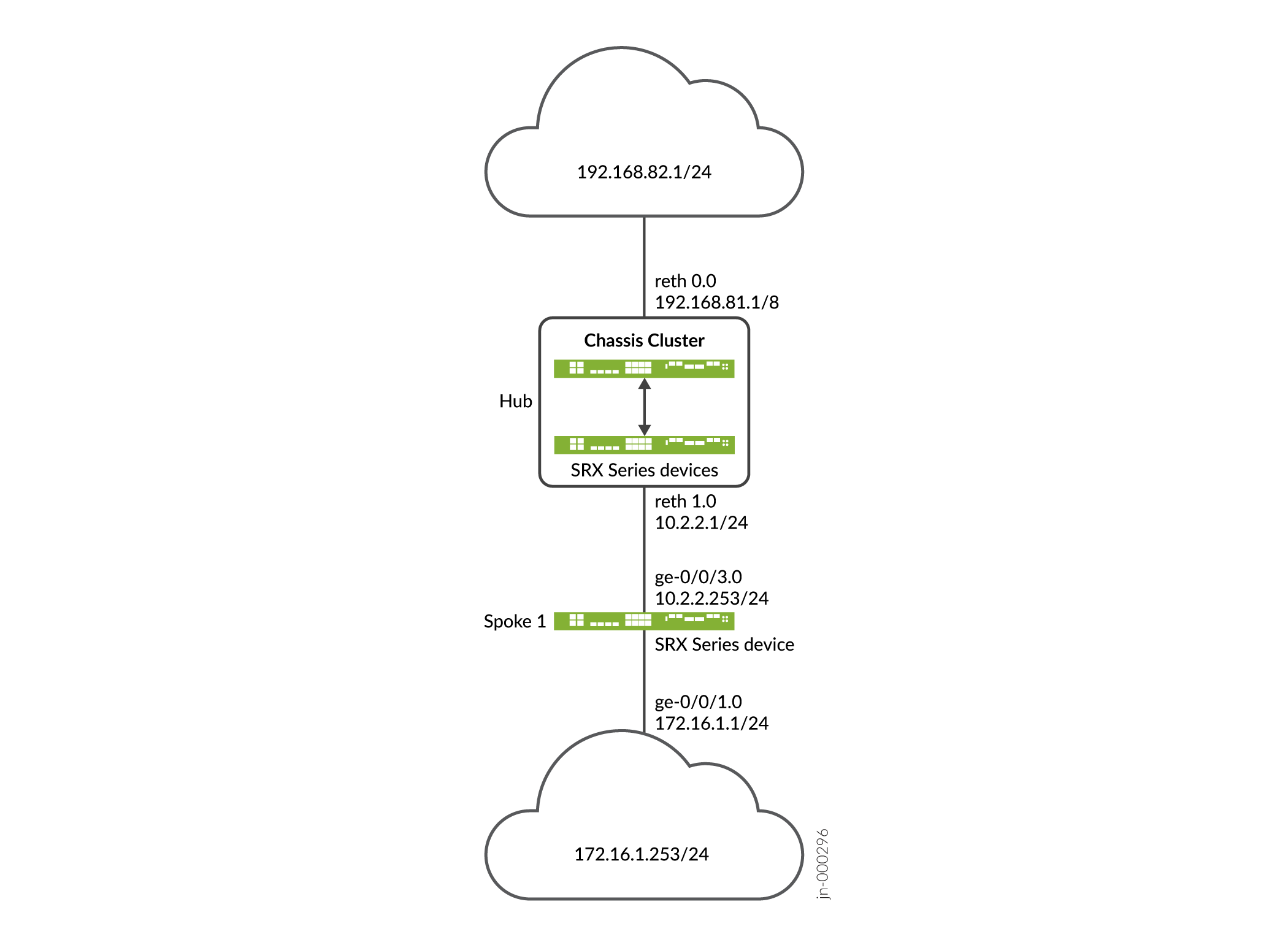
Configuration
Configuring the Hub
CLI Quick Configuration
To quickly configure this example, copy the following commands, paste them
into a text file, remove any line breaks, change any details necessary to
match your network configuration, copy and paste the commands into the CLI
at the [edit] hierarchy level, and then enter
commit from configuration mode.
set interfaces ge-0/0/2 gigether-options redundant-parent reth1 set interfaces ge-0/0/3 gigether-options redundant-parent reth0 set interfaces ge-8/0/2 gigether-options redundant-parent reth1 set interfaces ge-8/0/3 gigether-options redundant-parent reth0 set interfaces lo0 unit 0 family inet address 10.100.1.100/24 set interfaces lo0 redundant-pseudo-interface-options redundancy-group 1 set interfaces reth0 redundant-ether-options redundancy-group 1 set interfaces reth0 unit 0 family inet address 192.168.81.1/8 set interfaces reth1 redundant-ether-options redundancy-group 1 set interfaces reth1 unit 0 family inet address 10.2.2.1/24 set interfaces st0 unit 1 family inet set security ike proposal prop_ike authentication-method rsa-signatures set security ike proposal prop_ike dh-group group5 set security ike proposal prop_ike authentication-algorithm sha1 set security ike proposal prop_ike encryption-algorithm aes-256-cbc set security ike policy ikepol1 mode main set security ike policy ikepol1 proposals prop_ike set security ike policy ikepol1 certificate local-certificate Hub_ID set security ike gateway HUB_GW ike-policy ikepol1 set security ike gateway HUB_GW dynamic distinguished-name wildcard DC=Domain_component set security ike gateway HUB_GW dynamic ike-user-type group-ike-id set security ike gateway HUB_GW local-identity distinguished-name set security ike gateway HUB_GW external-interface reth1 set security ike gateway HUB_GW version v1-only set security ipsec proposal prop_ipsec protocol esp set security ipsec proposal prop_ipsec authentication-algorithm hmac-sha1-96 set security ipsec proposal prop_ipsec encryption-algorithm aes-192-cbc set security ipsec proposal prop_ipsec lifetime-seconds 3600 set security ipsec proposal prop_ipsec lifetime-kilobytes 150000 set security ipsec policy ipsecpol1 perfect-forward-secrecy keys group5 set security ipsec policy ipsecpol1 proposals prop_ipsec set security ipsec vpn HUB_VPN bind-interface st0.1 set security ipsec vpn HUB_VPN ike gateway HUB_GW set security ipsec vpn HUB_VPN ike ipsec-policy ipsecpol1 set security ipsec vpn HUB_VPN traffic-selector ts1 local-ip 192.0.0.0/8 set security ipsec vpn HUB_VPN traffic-selector ts1 remote-ip 172.0.0.0/8 set security pki ca-profile rsa ca-identity rsa set security pki ca-profile rsa revocation-check disable set security zones security-zone trust host-inbound-traffic system-services all set security zones security-zone trust host-inbound-traffic protocols all set security zones security-zone trust interfaces st0.1 set security zones security-zone trust interfaces reth0.0 set security zones security-zone untrust host-inbound-traffic system-services all set security zones security-zone untrust host-inbound-traffic protocols all set security zones security-zone untrust interfaces lo0.0 set security zones security-zone untrust interfaces reth1.0 set security policies default-policy permit-all
You
can configure the CLI option reject-duplicate-connection at
the [edit security ike gateway gateway-name
dynamic] hierarchy level to retain an existing tunnel session
and reject negotiation requests for a new tunnel with the same IKE ID. By
default, an existing tunnel is tear down when a new tunnel with the same IKE
ID is established. The reject-duplicate-connection option
is only supported when ike-user-type group-ike-id or
ike-user-type shared-ike-id is configured for the IKE
gateway; the aaa access-profile
profile-name configuration is not supported
with this option.
Use the CLI option reject-duplicate-connection only when you
are certain that reestablishment of a new tunnel with the same IKE ID should
be rejected.
Step-by-Step Procedure
The following example requires you to navigate various levels in the configuration hierarchy. For instructions on how to do that, see CLI User Guide.
To configure the hub:
Configure interfaces.
[edit interfaces] user@host# set ge-0/0/2 gigether-options redundant-parent reth1 user@host# set ge-0/0/3 gigether-options redundant-parent reth0 user@host# set ge-8/0/2 gigether-options redundant-parent reth1 user@host# set ge-8/0/3 gigether-options redundant-parent reth0 user@host# set lo0 unit 0 family inet address 10.100.1.100/24 user@host# set lo0 redundant-pseudo-interface-options redundancy-group 1 user@host# set reth0 redundant-ether-options redundancy-group 1 user@host# set reth0 unit 0 family inet address 192.168.81.1/8 user@host# set reth1 redundant-ether-options redundancy-group 1 user@host# set reth1 unit 0 family inet address 10.2.2.1/24 user@host# set st0 unit 1 family inet
Configure Phase 1 options.
[edit security ike proposal prop_ike] user@host# set authentication-method rsa-signatures user@host# set dh-group group5 user@host# set authentication-algorithm sha1 user@host# set encryption-algorithm aes-256-cbc [edit security ike policy ikepol1] user@host# set mode main user@host# set proposals prop_ike user@host# set certificate local-certificate Hub_ID [edit security ike gateway HUB_GW] user@host# set ike-policy ikepol1 user@host# set dynamic distinguished-name wildcard DC=Domain_component user@host# set dynamic ike-user-type group-ike-id user@host# set local-identity distinguished-name user@host# set external-interface reth1 user@host# set version v1-only
Configure Phase 2 options.
[edit security ipsec proposal prop_ipsec] user@host# set protocol esp user@host# set authentication-algorithm hmac-sha1-96 user@host# set encryption-algorithm aes-192-cbc user@host# set lifetime-seconds 3600 user@host# set lifetime-kilobytes 150000 [edit security ipsec policy ipsecpol1] user@host# set perfect-forward-secrecy keys group5 user@host# set proposals prop_ipsec [edit security ipsec HUB_VPN] user@host# set bind-interface st0.1 user@host# set ike gateway HUB_GW user@host# set ike ipsec-policy ipsecpol1 user@host# set traffic-selector ts1 local-ip 192.0.0.0/8 user@host# set traffic-selector ts1 remote-ip 172.0.0.0/8
Configure certificate information.
[edit security pki] user@host# set ca-profile rsa ca-identity rsa user@host# set ca-profile rsa revocation-check disable
Configure security zones.
[edit security zones security-zone trust] user@host# set host-inbound-traffic system-services all user@host# set host-inbound-traffic protocols all user@host# set interfaces st0.1 user@host# set interfaces reth0.0 [edit security zones security-zone untrust] user@host# set host-inbound-traffic system-services all user@host# set host-inbound-traffic protocols all user@host# set interfaces lo0.0 user@host# set interfaces reth1.0 [edit security policies] user@host# set default-policy permit-all
Results
From configuration mode, confirm your configuration by entering the
show interfaces, show security ike,
show security ipsec, show security
pki, show security zones, and show
security policies commands. If the output does not display the
intended configuration, repeat the instructions in this example to correct
the configuration.
[edit]
user@host# show interfaces
ge-0/0/2 {
gigether-options {
redundant-parent reth1;
}
}
ge-0/0/3 {
gigether-options {
redundant-parent reth0;
}
}
lo0 {
unit 0 {
family inet {
address 10.100.1.100/24;
}
}
redundant-pseudo-interface-options {
redundancy-group 1;
}
}
reth0 {
redundant-ether-options {
redundancy-group 1;
}
unit 0 {
family inet {
address 192.168.81.1/8;
}
}
}
reth1 {
redundant-ether-options {
redundancy-group 1;
}
unit 0 {
family inet {
address 10.2.2.1/24;
}
}
}
st0 {
unit 1 {
family inet;
}
}
[edit]
user@host# show security ike
proposal prop_ike {
authentication-method rsa-signatures;
dh-group group5;
authentication-algorithm sha1;
encryption-algorithm aes-256-cbc;
}
policy ikepol1 {
mode main;
proposals prop_ike;
certificate {
local-certificate Hub_ID;
}
}
gateway HUB_GW {
ike-policy ikepol1;
dynamic distinguished-name wildcard DC=Domain_component;
dynamic ike-user-type group-ike-id;
local-identity distinguished-name;
external-interface reth1;
version v1-only;
}
[edit]
user@host# show security ipsec
proposal prop_ipsec {
protocol esp;
authentication-algorithm hmac-sha1-96;
encryption-algorithm aes-192-cbc;
lifetime-seconds 3600;
lifetime-kilobytes 150000;
}
policy ipsecpol1 {
perfect-forward-secrecy {
keys group5;
}
proposals prop_ipsec;
}
vpn HUB_VPN {
bind-interface st0.1;
ike {
gateway HUB_GW;
ipsec-policy ipsecpol1;
}
traffic-selector ts1 {
local-ip 192.0.0.0/8;
remote-ip 172.0.0.0/8;
}
}
[edit]
user@host# show security pki
ca-profile rsa {
ca-identity rsa;
revocation-check {
disable;
}
}
[edit]
user@host# show security zones
security-zone trust {
host-inbound-traffic {
system-services {
all;
}
protocols {
all;
}
}
interfaces {
st0.1;
reth0.0;
}
}
security-zone untrust {
host-inbound-traffic {
system-services {
all;
}
protocols {
all;
}
}
interfaces {
lo0.0;
reth1.0;
}
}
[edit]
user@host# show security policies
default-policy {
permit-all;
}
If you are done configuring the device, enter commit from
configuration mode.
Configuring the Spoke
CLI Quick Configuration
To quickly configure this example, copy the following commands, paste them
into a text file, remove any line breaks, change any details necessary to
match your network configuration, copy and paste the commands into the CLI
at the [edit] hierarchy level, and then enter
commit from configuration mode.
set interfaces ge-0/0/1 unit 0 family inet address 172.16.1.1/24 set interfaces ge-0/0/3 unit 0 family inet address 10.2.2.253/24 set interfaces st0 unit 1 family inet set security ike proposal prop_ike authentication-method rsa-signatures set security ike proposal prop_ike dh-group group5 set security ike proposal prop_ike authentication-algorithm sha1 set security ike proposal prop_ike encryption-algorithm aes-256-cbc set security ike policy ikepol1 mode main set security ike policy ikepol1 proposals prop_ike set security ike policy ikepol1 certificate local-certificate Spoke1_ID set security ike gateway SPOKE_GW ike-policy ikepol1 set security ike gateway SPOKE_GW address 10.2.2.1 set security ike gateway SPOKE_GW local-identity distinguished-name set security ike gateway SPOKE_GW remote-identity distinguished-name container DC=Domain_component set security ike gateway SPOKE_GW external-interface ge-0/0/3.0 set security ike gateway SPOKE_GW version v1-only set security ipsec proposal prop_ipsec protocol esp set security ipsec proposal prop_ipsec authentication-algorithm hmac-sha1-96 set security ipsec proposal prop_ipsec encryption-algorithm aes-192-cbc set security ipsec proposal prop_ipsec lifetime-seconds 3600 set security ipsec proposal prop_ipsec lifetime-kilobytes 150000 set security ipsec policy ipsecpol1 perfect-forward-secrecy keys group5 set security ipsec policy ipsecpol1 proposals prop_ipsec set security ipsec vpn SPOKE_VPN bind-interface st0.1 set security ipsec vpn SPOKE_VPN ike gateway SPOKE_GW set security ipsec vpn SPOKE_VPN ike ipsec-policy ipsecpol1 set security ipsec vpn SPOKE_VPN traffic-selector ts1 local-ip 172.0.0.0/8 set security ipsec vpn SPOKE_VPN traffic-selector ts1 remote-ip 192.0.0.0/8 set security ipsec vpn SPOKE_VPN establish-tunnels immediately set security pki ca-profile rsa ca-identity rsa set security pki ca-profile rsa revocation-check disable set security zones security-zone trust host-inbound-traffic system-services all set security zones security-zone trust host-inbound-traffic protocols all set security zones security-zone trust interfaces st0.1 set security zones security-zone trust interfaces ge-0/0/3.0 set security zones security-zone untrust host-inbound-traffic system-services all set security zones security-zone untrust host-inbound-traffic protocols all set security zones security-zone untrust interfaces ge-0/0/1.0 set security policies default-policy permit-all
Step-by-Step Procedure
The following example requires you to navigate various levels in the configuration hierarchy. For instructions on how to do that, see CLI User Guide.
To configure the hub:
Configure interfaces.
[edit interfaces] user@host# set ge-0/0/1 unit 0 family inet address 172.16.1.1/24 user@host# set ge-0/0/3 unit 0 family inet address 10.2.2.253/24 user@host# set st0 unit 1 family inet
Configure Phase 1 options.
[edit security ike proposal prop_ike] user@host# set authentication-method rsa-signatures user@host# set dh-group group5 user@host# set authentication-algorithm sha1 user@host# set encryption-algorithm aes-256-cbc [edit security ike policy ikepol1] user@host# set mode main user@host# set proposals prop_ike user@host# set certificate local-certificate Spoke1_ID [edit security ike gateway SPOKE_GW] user@host# set ike-policy ikepol1 user@host# set address 10.2.2.1 user@host# set local-identity distinguished-name user@host# set remote-identity distinguished-name container DC=Domain_component user@host# set external-interface ge-0/0/3.0 user@host# set version v1-only
Configure Phase 2 options.
[edit security ipsec proposal prop_ipsec] user@host# set protocol esp user@host# set authentication-algorithm hmac-sha1-96 user@host# set encryption-algorithm aes-192-cbc user@host# set lifetime-seconds 3600 user@host# set lifetime-kilobytes 150000 [edit security ipsec policy ipsecpol1] user@host# set perfect-forward-secrecy keys group5 user@host# set proposals prop_ipsec [edit security ipsec SPOKE_VPN] user@host# set bind-interface st0.1 user@host# set ike gateway SPOKE_GW user@host# set ike ipsec-policy ipsecpol1 user@host# set traffic-selector ts1 local-ip 172.0.0.0/8 user@host# set traffic-selector ts1 remote-ip 192.0.0.0/8 user@host# set establish-tunnels immediately
Configure certificate information.
[edit security pki] user@host# set ca-profile rsa ca-identity rsa user@host# set ca-profile rsa revocation-check disable
Configure security zones.
[edit security zones security-zone trust] user@host# set host-inbound-traffic system-services all user@host# set host-inbound-traffic protocols all user@host# set interfaces st0.1 user@host# set interfaces ge-0/0/3.0 [edit security zones security-zone untrust] user@host# set host-inbound-traffic system-services all user@host# set host-inbound-traffic protocols all user@host# set interfaces ge-0/0/1.0 [edit security policies] user@host# set default-policy permit-all
Results
From configuration mode, confirm your configuration by entering the
show interfaces, show security ike,
show security ipsec, show security
pki, show security zones, and show
security policies commands. If the output does not display the
intended configuration, repeat the instructions in this example to correct
the configuration.
[edit]
user@host# show interfaces
ge-0/0/1 {
unit 0 {
family inet {
address 172.16.1.1/24;
}
}
}
ge-0/0/3 {
unit 0 {
family inet {
address 10.2.2.253/24;
}
}
}
st0 {
unit 1 {
family inet;
}
}
[edit]
user@host# show security ike
proposal prop_ike {
authentication-method rsa-signatures;
dh-group group5;
authentication-algorithm sha1;
encryption-algorithm aes-256-cbc;
}
policy ikepol1 {
mode main;
proposals prop_ike;
certificate {
local-certificate Spoke1_ID;
}
}
gateway SPOKE_GW {
ike-policy ikepol1;
address 10.2.2.1;
local-identity distinguished-name;
remote-identity distinguished-name container DC=Domain_component;
external-interface ge-0/0/3.0;
version v1-only;
}
[edit]
user@host# show security ipsec
proposal prop_ipsec {
protocol esp;
authentication-algorithm hmac-sha1-96;
encryption-algorithm aes-192-cbc;
lifetime-seconds 3600;
lifetime-kilobytes 150000;
}
policy ipsecpol1 {
perfect-forward-secrecy {
keys group5;
}
proposals prop_ipsec;
}
vpn SPOKE_VPN {
bind-interface st0.1;
ike {
gateway SPOKE_GW;
ipsec-policy ipsecpol1;
}
traffic-selector ts1 {
local-ip 172.0.0.0/8;
remote-ip 192.0.0.0/8;
}
establish-tunnels immediately;
}
[edit]
user@host# show security pki
ca-profile rsa {
ca-identity rsa;
revocation-check {
disable;
}
}
[edit]
user@host# show security zones
security-zone trust {
host-inbound-traffic {
system-services {
all;
}
protocols {
all;
}
}
interfaces {
st0.1;
ge-0/0/3.0;
}
}
security-zone untrust {
host-inbound-traffic {
system-services {
all;
}
protocols {
all;
}
}
interfaces {
ge-0/0/1.0;
}
}
[edit]
user@host# show security policies
default-policy {
permit-all;
}
If you are done configuring the device, enter commit from
configuration mode.
Verification
Confirm that the configuration is working properly.
Verifying Tunnels
Purpose
Verify that tunnels are established between the AutoVPN hub and spoke.
Action
From operational mode, enter the show security ike
security-associations and show security ipsec
security-associations commands on the hub.
user@host> show security ike security-associations
node0:
--------------------------------------------------------------------------
Index State Initiator cookie Responder cookie Mode Remote Address
1350248074 UP d195bce6ccfcf9af 8f1569c6592c8408 Main 10.2.2.253
user@host> show security ipsec security-associations
node0:
--------------------------------------------------------------------------
Total active tunnels: 1
ID Algorithm SPI Life:sec/kb Mon lsys Port Gateway
<77594650 ESP:aes-cbc-192/sha1 ac97cb1 2799/ 150000 - root 500 10.2.2.253
>77594650 ESP:aes-cbc-192/sha1 828dc013 2798/ 150000 - root 500 10.2.2.253
user@host> show security ipsec security-associations detail
node0:
--------------------------------------------------------------------------
ID: 77594650 Virtual-system: root, VPN Name: HUB_VPN
Local Gateway: 10.2.2.1, Remote Gateway: 10.2.2.253
Traffic Selector Name: ts1
Local Identity: ipv4(192.0.0.0-192.255.255.255)
Remote Identity: ipv4(172.0.0.0-172.255.255.255)
Version: IKEv1
DF-bit: clear, Bind-interface: st0.1
Port: 500, Nego#: 2, Fail#: 0, Def-Del#: 0 Flag: 0x24608b29
Tunnel events:
Tue Dec 30 2014 11:30:21 -0800: IPSec SA negotiation successfully completed (1 times)
Tue Dec 30 2014 11:30:20 -0800: Tunnel is ready. Waiting for trigger event or peer to trigger negotiation (1 times)
Tue Dec 30 2014 11:30:20 -0800: IKE SA negotiation successfully completed (3 times)
Location: FPC 5, PIC 0, KMD-Instance 1
Direction: inbound, SPI: ac97cb1, AUX-SPI: 0
Hard lifetime: Expires in 2796 seconds
Lifesize Remaining: 150000 kilobytes
Soft lifetime: Expires in 2211 seconds
Mode: Tunnel(0 0), Type: dynamic, State: installed
Protocol: ESP, Authentication: hmac-sha1-96, Encryption: aes-cbc (192 bits)
Anti-replay service: counter-based enabled, Replay window size: 64
Location: FPC 5, PIC 0, KMD-Instance 1
Direction: outbound, SPI: 828dc013, AUX-SPI: 0
Hard lifetime: Expires in 2796 seconds
Lifesize Remaining: 150000 kilobytes
Soft lifetime: Expires in 2211 seconds
Mode: Tunnel(0 0), Type: dynamic, State: installed
Protocol: ESP, Authentication: hmac-sha1-96, Encryption: aes-cbc (192 bits)
Anti-replay service: counter-based enabled, Replay window size: 64
From operational mode, enter the show security ike
security-associations and show security ipsec
security-associations commands on the spoke.
user@host> show security ike security-associations
Index State Initiator cookie Responder cookie Mode Remote Address
276505646 UP d195bce6ccfcf9af 8f1569c6592c8408 Main 10.2.2.1
user@host> show security ipsec security-associations
Total active tunnels: 1
ID Algorithm SPI Life:sec/kb Mon lsys Port Gateway
<69206018 ESP:aes-cbc-192/sha1 828dc013 2993/ 150000 - root 500 10.2.2.1
>69206018 ESP:aes-cbc-192/sha1 ac97cb1 2993/ 150000 - root 500 10.2.2.1
user@host> show security ipsec security-associations detail
ID: 69206018 Virtual-system: root, VPN Name: SPOKE_VPN
Local Gateway: 10.2.2.253, Remote Gateway: 10.2.2.1
Traffic Selector Name: ts1
Local Identity: ipv4(172.0.0.0-172.255.255.255)
Remote Identity: ipv4(192.0.0.0-192.255.255.255)
Version: IKEv1
DF-bit: clear, Bind-interface: st0.1
Port: 500, Nego#: 0, Fail#: 0, Def-Del#: 0 Flag: 0x2c608b29
Tunnel events:
Tue Dec 30 2014 11:30:20 -0800: IPSec SA negotiation successfully completed (1 times)
Tue Dec 30 2014 11:30:20 -0800: IKE SA negotiation successfully completed (1 times)
Tue Dec 30 2014 11:26:11 -0800: Tunnel is ready. Waiting for trigger event or peer to trigger negotiation (1 times)
Location: FPC 1, PIC 0, KMD-Instance 1
Direction: inbound, SPI: 828dc013, AUX-SPI: 0
Hard lifetime: Expires in 2991 seconds
Lifesize Remaining: 150000 kilobytes
Soft lifetime: Expires in 2369 seconds
Mode: Tunnel(0 0), Type: dynamic, State: installed
Protocol: ESP, Authentication: hmac-sha1-96, Encryption: aes-cbc (192 bits)
Anti-replay service: counter-based enabled, Replay window size: 64
Location: FPC 1, PIC 0, KMD-Instance 1
Direction: outbound, SPI: ac97cb1, AUX-SPI: 0
Hard lifetime: Expires in 2991 seconds
Lifesize Remaining: 150000 kilobytes
Soft lifetime: Expires in 2369 seconds
Mode: Tunnel(0 0), Type: dynamic, State: installed
Protocol: ESP, Authentication: hmac-sha1-96, Encryption: aes-cbc (192 bits)
Anti-replay service: counter-based enabled, Replay window size: 64
Meaning
The show security ike security-associations command lists
all active IKE Phase 1 SAs. The show security ipsec
security-associations command lists all active IKE Phase 2 SAs.
The hub shows one active tunnel to the spoke while the spoke shows one
active tunnel to the hub.
If no SAs are listed for IKE Phase 1, then there was a problem with Phase 1 establishment. Check the IKE policy parameters and external interface settings in your configuration. Phase 1 proposal parameters must match on the hub and spoke.
If no SAs are listed for IKE Phase 2, then there was a problem with Phase 2 establishment. Check the IKE policy parameters and external interface settings in your configuration. Phase 2 proposal parameters must match on the hub and spoke.
Verifying Traffic Selectors
Purpose
Verify the traffic selectors.
Action
From operational mode, enter the show security ipsec traffic-selector
interface-name st0.1 command on the hub.
user@host> show security ipsec traffic-selector interface-name st0.1 node0: -------------------------------------------------------------------------- Source IP Destination IP Interface Tunnel-id IKE-ID 192.0.0.0-192.255.255.255 172.0.0.0-172.255.255.255 st0.1 77594650 DC=Domain_component, CN=Spoke1_ID, OU=Sales, O=XYZ, L=Sunnyvale, ST=CA, C=US
From operational mode, enter the show security ipsec traffic-selector
interface-name st0.1 command on the spoke.
user@host> show security ipsec traffic-selector interface-name st0.1 Source IP Destination IP Interface Tunnel-id IKE-ID 172.0.0.0-172.255.255.255 192.0.0.0-192.255.255.255 st0.1 69206018 DC=Domain_component, CN=Hub_ID, OU=Sales, O=XYZ, L=Sunnyvale, ST=CA, C=US
Meaning
A traffic selector is an agreement between IKE peers to permit traffic through a tunnel if the traffic matches a specified pair of local and remote addresses. Only traffic that conforms to a traffic selector is permitted through an SA. Traffic selectors are negotiated between the initiator and the responder (the hub).
Example: Ensuring VPN Tunnel Availability with AutoVPN and Traffic Selectors
Georedundancy is the deployment of multiple geographically distant sites so that traffic can continue to flow over a provider network even if there is a power outage, a natural disaster, or other catastrophic event that affects a site. In a mobile provider network, multiple Evolved Node B (eNodeB) devices can be connected to the core network through georedundant IPsec VPN gateways on the firewalls. The alternate routes to the eNodeB devices are distributed to the core network using a dynamic routing protocol.
This example configures AutoVPN hubs with multiple traffic selectors on the firewalls to ensure that there are georedundant IPsec VPN gateways to eNodeB devices. Auto route insertion (ARI) is used to automatically insert routes toward the eNodeB devices in the routing tables on the hubs. ARI routes are then distributed to the provider’s core network through BGP. The example is using the certificate based authentication. For authentication with preshared key, set up a similar configuration shown at Example: Configuring Basic AutoVPN with iBGP.
Requirements
This example uses the following hardware and software components:
-
Two firewalls connected and configured in a chassis cluster. The chassis cluster is AutoVPN hub A.
-
One firewall configured as AutoVPN hub B.
-
Supported Junos OS Release.
-
eNodeB devices that can establish IPsec VPN tunnels with AutoVPN hubs. eNodeB devices are third-party network equipment providers that initiate a VPN tunnel with AutoVPN hubs.
-
Digital certificates enrolled in the hubs and the eNodeB devices that allow the devices to authenticate each other.
Before you begin:
-
Obtain the address of the certificate authority (CA) and the information they require (such as the challenge password) when you submit requests for local certificates.
-
Enroll the digital certificates in each device. See Enroll Certificate.
This example uses the BGP dynamic routing protocol to advertise routes toward the eNodeB devices to the core network.
Overview
In this example, two AutoVPN hubs are configured with multiple traffic selectors on the firewalls to provide georedundant IPsec VPN gateways to eNodeB devices. ARI automatically inserts routes to the eNodeB devices in the routing tables on the hubs. ARI routes are then distributed to the provider’s core network through BGP.
Certain Phase 1 and Phase 2 IKE tunnel options configured on the AutoVPN hubs and eNodeB devices must have the same values. Table 19 shows the values used in this example:
|
Option |
Value |
|---|---|
|
IKE proposal: |
|
|
Authentication method |
rsa-signatures |
|
Diffie-Hellman (DH) group |
group5 |
|
Authentication algorithm |
sha-1 |
|
Encryption algorithm |
aes-256-cbc |
|
IKE policy: |
|
|
Certificate |
local-certificate |
|
IKE gateway: |
|
|
Dynamic |
distinguished name wildcard DC=Common_component |
|
IKE user type |
group IKE id |
|
Dead peer detection |
probe-idle-tunnel |
|
Local identity |
distinguished name |
|
Version |
v2-only |
|
IPsec proposal: |
|
|
Protocol |
esp |
|
Authentication algorithm |
hmac-sha1-96 |
|
Encryption algorithm |
aes-256-cbc |
|
IPsec policy: |
|
|
Perfect Forward Secrecy (PFS) group |
group5 |
In this example, the default security policy that permits all traffic is used for all devices. More restrictive security policies should be configured for production environments. For simplicity, the configuration on the firewalls allows all types of inbound traffic; this configuration is not recommended for production deployments.
Topology
Figure 9 shows the firewalls to be configured for this example.
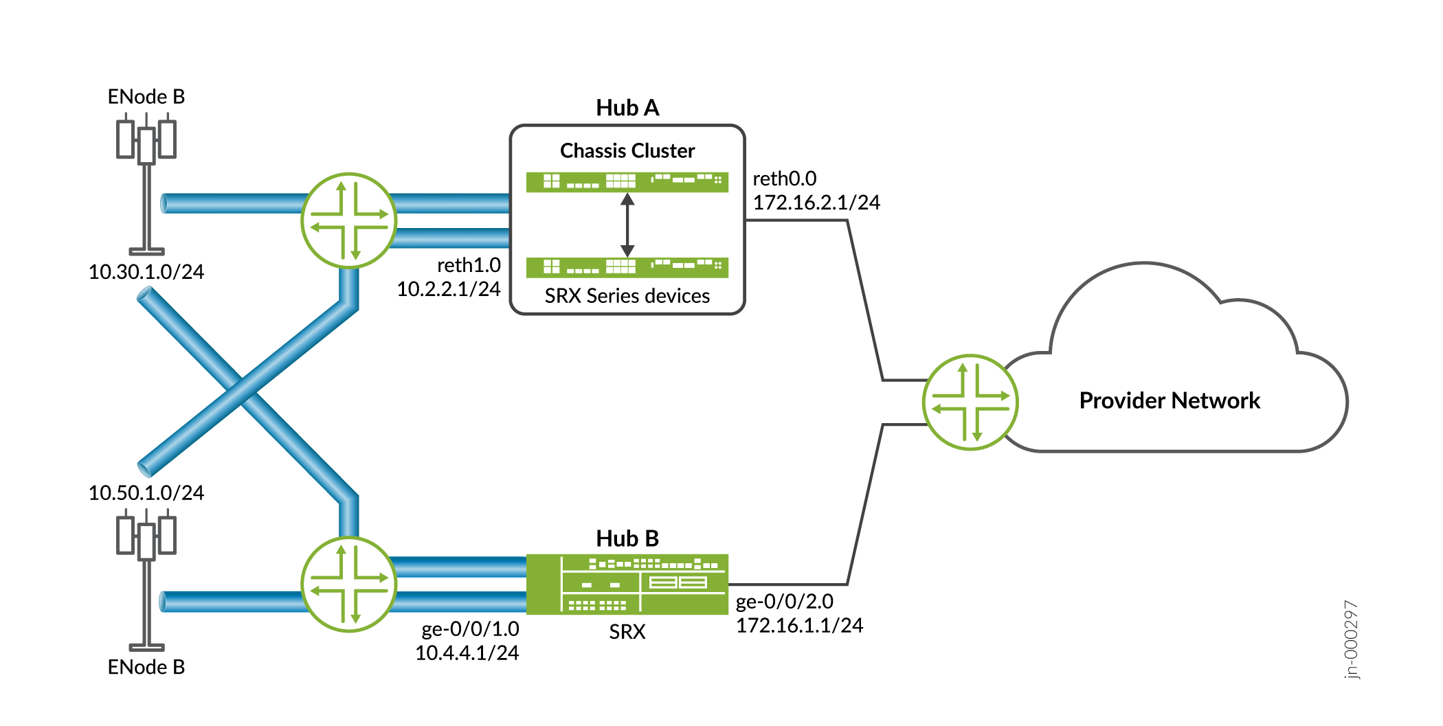
Configuration
Configuring Hub A
CLI Quick Configuration
To quickly configure this example, copy the following commands, paste them
into a text file, remove any line breaks, change any details necessary to
match your network configuration, copy and paste the commands into the CLI
at the [edit] hierarchy level, and then enter
commit from configuration mode.
set interfaces ge-0/0/2 gigether-options redundant-parent reth1 set interfaces ge-0/0/3 gigether-options redundant-parent reth0 set interfaces ge-8/0/2 gigether-options redundant-parent reth1 set interfaces ge-8/0/3 gigether-options redundant-parent reth0 set interfaces lo0 unit 0 family inet address 10.100.1.100/24 set interfaces lo0 redundant-pseudo-interface-options redundancy-group 1 set interfaces reth0 redundant-ether-options redundancy-group 1 set interfaces reth0 unit 0 family inet address 172.16.2.1/24 set interfaces reth1 redundant-ether-options redundancy-group 1 set interfaces reth1 unit 0 family inet address 10.2.2.1/24 set interfaces st0 unit 1 family inet set security ike proposal prop_ike authentication-method rsa-signatures set security ike proposal prop_ike dh-group group5 set security ike proposal prop_ike authentication-algorithm sha1 set security ike proposal prop_ike encryption-algorithm aes-256-cbc set security ike policy ph1_ike_policy proposals prop_ike set security ike policy ph1_ike_policy certificate local-certificate HubA_certificate set security ike gateway HUB_GW ike-policy ph1_ike_policy set security ike gateway HUB_GW dynamic distinguished-name wildcard DC=Common_component set security ike gateway HUB_GW dynamic ike-user-type group-ike-id set security ike gateway HUB_GW dead-peer-detection probe-idle-tunnel set security ike gateway HUB_GW local-identity distinguished-name set security ike gateway HUB_GW external-interface reth1 set security ike gateway HUB_GW version v2-only set security ipsec proposal prop_ipsec protocol esp set security ipsec proposal prop_ipsec authentication-algorithm hmac-sha1-96 set security ipsec proposal prop_ipsec encryption-algorithm aes-256-cbc set security ipsec policy ph2_ipsec_policy perfect-forward-secrecy keys group5 set security ipsec policy ph2_ipsec_policy proposals prop_ipsec set security ipsec vpn HUB_VPN bind-interface st0.1 set security ipsec vpn HUB_VPN ike gateway HUB_GW set security ipsec vpn HUB_VPN ike ipsec-policy ph2_ipsec_policy set security ipsec vpn HUB_VPN traffic-selector ts1 local-ip 172.16.0.0/16 set security ipsec vpn HUB_VPN traffic-selector ts1 remote-ip 10.50.0.0/16 set security ipsec vpn HUB_VPN traffic-selector ts2 local-ip 172.16.0.0/16 set security ipsec vpn HUB_VPN traffic-selector ts2 remote-ip 10.30.0.0/16 set protocols bgp group internal-peers type internal set protocols bgp group internal-peers local-address 172.16.2.1 set protocols bgp group internal-peers export inject_ts1_routes set protocols bgp group internal-peers export inject_ts2_routes set protocols bgp group internal-peers export inject_up_routes set protocols bgp group internal-peers neighbor 172.16.2.4 set policy-options policy-statement inject_ts1_routes term cp_allow from protocol static set policy-options policy-statement inject_ts1_routes term cp_allow from route-filter 10.30.1.0/24 orlonger set policy-options policy-statement inject_ts1_routes term cp_allow from route-filter 10.30.1.0/24 orlonger set policy-options policy-statement inject_ts1_routes term cp_allow then next-hop self set policy-options policy-statement inject_ts1_routes term cp_allow then accept set policy-options policy-statement inject_ts2_routes term mp_allow from protocol static set policy-options policy-statement inject_ts2_routes term mp_allow from route-filter 10.50.1.0/24 orlonger set policy-options policy-statement inject_ts2_routes term mp_net_allow from route-filter 10.50.2.0/24 orlonger set policy-options policy-statement inject_ts2_routes term mp_net_allow then next-hop self set policy-options policy-statement inject_ts2_routes term mp_net_allow then accept set policy-options policy-statement inject_up_routes term up_allow from protocol static set policy-options policy-statement inject_up_routes term up_allow from route-filter 172.16.1.0/24 orlonger set policy-options policy-statement inject_up_routes term up_allow from route-filter 172.16.2.0/24 orlonger set policy-options policy-statement inject_up_routes term up_allow then next-hop self set policy-options policy-statement inject_up_routes term up_allow then accept set security pki ca-profile csa ca-identity csa set security pki ca-profile csa revocation-check disable set security zones security-zone trust host-inbound-traffic system-services all set security zones security-zone trust host-inbound-traffic protocols all set security zones security-zone trust interfaces st0.1 set security zones security-zone trust interfaces reth0.0 set security zones security-zone untrust host-inbound-traffic system-services all set security zones security-zone untrust host-inbound-traffic protocols all set security zones security-zone untrust interfaces lo0.0 set security zones security-zone untrust interfaces reth1.0 set security policies default-policy permit-all
Step-by-Step Procedure
The following example requires you to navigate various levels in the configuration hierarchy. For instructions on how to do that, see CLI User Guide.
To configure hub A:
-
Configure interfaces.
[edit interfaces] user@host# set ge-0/0/2 gigether-options redundant-parent reth1 user@host# set ge-0/0/3 gigether-options redundant-parent reth0 user@host# set ge-8/0/2 gigether-options redundant-parent reth1 user@host# set ge-8/0/3 gigether-options redundant-parent reth0 user@host# set lo0 unit 0 family inet address 10.100.1.100/24 user@host# set lo0 redundant-pseudo-interface-options redundancy-group 1 user@host# set reth0 redundant-ether-options redundancy-group 1 user@host# set reth0 unit 0 family inet address 172.16.2.1/24 user@host# set reth1 redundant-ether-options redundancy-group 1 user@host# set reth1 unit 0 family inet address 10.2.2.1/24 user@host# set st0 unit 1 family inet
-
Configure Phase 1 options.
[edit security ike proposal prop_ike] user@host# set authentication-method rsa-signatures user@host# set dh-group group5 user@host# set authentication-algorithm sha1 user@host# set encryption-algorithm aes-256-cbc [edit security ike policy ph1_ike_policy] user@host# set proposals prop_ike user@host# set certificate local-certificate HubA_certificate [edit security ike gateway HUB_GW] user@host# set ike-policy ph1_ike_policy user@host# set dynamic distinguished-name wildcard DC=Common_component user@host# set dynamic ike-user-type group-ike-id user@host# set dead-peer-detection probe-idle-tunnel user@host# set local-identity distinguished-name user@host# set external-interface reth1 user@host# set version v2-only
-
Configure Phase 2 options.
[edit security ipsec proposal prop_ipsec] user@host# set protocol esp user@host# set authentication-algorithm hmac-sha1-96 user@host# set encryption-algorithm aes-256-cbc [edit security ipsec policy ph2_ipsec_policy] user@host# set perfect-forward-secrecy keys group5 user@host# set proposals prop_ipsec [edit security ipsec vpn HUB_VPN] user@host# set bind-interface st0.1 user@host# set ike gateway HUB_GW user@host# set ike ipsec-policy ph2_ipsec_policy user@host# set traffic-selector ts1 local-ip 172.16.0.0/16 user@host# set traffic-selector ts1 remote-ip 10.50.0.0/16 user@host# set traffic-selector ts2 local-ip 172.16.0.0/16 user@host# set traffic-selector ts2 remote-ip 10.30.0.0/16
-
Configure the BGP routing protocol.
[edit protocols bgp group internal-peers] user@host# set type internal user@host# set local-address 172.16.2.1 user@host# set export inject_ts1_routes user@host# set export inject_ts2_routes user@host# set export inject_up_routes user@host# set neighbor 172.16.2.4
-
Configure routing options.
[edit policy-options policy-statement inject_ts1_routes] user@host# set term cp_allow from protocol static user@host# set term cp_allow from route-filter 10.30.2.0/24 orlonger user@host# set term cp_allow from route-filter 10.30.1.0/24 orlonger user@host# set term cp_allow then next-hop self user@host# set term cp_allow then accept [edit policy-options policy-statement inject_ts2_routes] user@host# set term mp_allow from protocol static user@host# set term mp_allow from route-filter 10.50.1.0/24 orlonger user@host# set term mp_allow from route-filter 10.50.2.0/24 orlonger user@host# set term mp_allow then next-hop self user@host# set term mp_allow then accept [edit policy-options policy-statement inject_up_routes] user@host# set term up_allow from protocol static user@host# set term up_allow from route-filter 172.16.1.0/24 orlonger user@host# set term up_allow from route-filter 172.16.2.0/24 orlonger user@host# set term up_allow then next-hop self user@host# set term up_allow then accept
-
Configure certificate information.
[edit security pki] user@host# set ca-profile csa ca-identity csa user@host# set ca-profile csa revocation-check disable
-
Configure security zones.
[edit security zones security-zone trust] user@host# set host-inbound-traffic system-services all user@host# set host-inbound-traffic protocols all user@host# set interfaces st0.1 user@host# set interfaces reth0.0 [edit security zones security-zone untrust] user@host# set host-inbound-traffic system-services all user@host# set host-inbound-traffic protocols all user@host# set interfaces lo0.0 user@host# set interfaces reth1.0 [edit security policies] user@host# set default-policy permit-all
Results
From configuration mode, confirm your configuration by entering the
show interfaces
show security ike, show security ipsec,
show protocols bgp, show
policy-options, show security pki,
show security zones, and show security
policies commands. If the output does not display the intended
configuration, repeat the instructions in this example to correct the
configuration.
[edit]
user@host# show interfaces
ge-0/0/2 {
gigether-options {
redundant-parent reth1;
}
}
ge-0/0/3 {
gigether-options {
redundant-parent reth0;
}
}
ge-8/0/2 {
gigether-options {
redundant-parent reth1;
}
}
ge-8/0/3 {
gigether-options {
redundant-parent reth0;
}
}
lo0 {
unit 0 {
family inet {
address 10.100.1.100/24;
}
}
redundant-pseudo-interface-options {
redundancy-group 1;
}
}
reth0 {
redundant-ether-options {
redundancy-group 1;
}
unit 0 {
family inet {
address 172.16.2.1/16;
}
}
}
reth1 {
redundant-ether-options {
redundancy-group 1;
}
unit 0 {
family inet {
address 10.2.2.1/24;
}
}
}
st0 {
unit 1 {
family inet;
}
}
[edit]
user@host# show security ike
proposal prop_ike {
authentication-method rsa-signatures;
dh-group group5;
authentication-algorithm sha1;
encryption-algorithm aes-256-cbc;
}
policy ph1_ike_policy {
proposals prop_ike;
certificate {
local-certificate HubA_certificate;
}
}
gateway HUB_GW {
ike-policy ph1_ike_policy;
dynamic {
distinguished-name {
wildcard DC=Common_component;
}
ike-user-type group-ike-id;
}
dead-peer-detection {
probe-idle-tunnel;
}
local-identity distinguished-name;
external-interface reth1;
version v2-only;
}
[edit]
user@host# show security ipsec
proposal prop_ipsec {
protocol esp;
authentication-algorithm hmac-sha1-96;
encryption-algorithm aes-256-cbc;
}
policy ph2_ipsec_policy {
perfect-forward-secrecy {
keys group5;
}
proposals prop_ipsec;
}
vpn HUB_VPN {
bind-interface st0.1;
ike {
gateway HUB_GW;
ipsec-policy ph2_ipsec_policy;
}
traffic-selector ts1 {
local-ip 172.16.0.0/16;
remote-ip 10.50.0.0/16;
}
traffic-selector ts2 {
local-ip 172.16.0.0/16;
remote-ip 10.30.0.0/16;
}
}
[edit]
user@host# show protocols bgp
group internal-peers {
type internal;
local-address 172.16.2.1;
export [ inject_ts1_routes inject_ts2_routes inject_up_routes ];
neighbor 172.16.2.4;
}
[edit]
user@host# show policy-options
policy-statement inject_ts1_routes {
term cp_allow {
from {
protocol static;
route-filter 10.30.2.0/24 orlonger;
route-filter 10.30.1.0/24 orlonger;
}
then {
next-hop self;
accept;
}
}
}
policy-statement inject_ts2_routes {
term mp_allow {
from {
protocol static;
route-filter 10.50.1.0/24 orlonger;
route-filter 10.50.2.0/24 orlonger;
}
then {
next-hop self;
accept;
}
}
}
policy-statement inject_up_routes {
term up_allow {
from {
protocol static;
route-filter 172.16.1.0/24 orlonger;
route-filter 172.16.2.0/24 orlonger;
}
then {
next-hop self;
accept;
}
}
}
[edit]
user@host# show security pki
ca-profile csa {
ca-identity csa;
revocation-check {
disable;
}
}
[edit]
user@host# show security zones
security-zone trust {
host-inbound-traffic {
system-services {
all;
}
protocols {
all;
}
}
interfaces {
st0.1;
reth0.0;
}
}
security-zone untrust {
host-inbound-traffic {
system-services {
all;
}
protocols {
all;
}
}
interfaces {
lo0.0;
reth1.0;
}
}
[edit]
user@host# show security policies
default-policy {
permit-all;
}
If you are done configuring the device, enter commit from
configuration mode.
Configuring Hub B
CLI Quick Configuration
To quickly configure this example, copy the following commands, paste them
into a text file, remove any line breaks, change any details necessary to
match your network configuration, copy and paste the commands into the CLI
at the [edit] hierarchy level, and then enter
commit from configuration mode.
set interfaces ge-0/0/1 unit 0 family inet address 10.4.4.1/24 set interfaces ge-0/0/2 unit 0 family inet address 172.16.1.1/16 set interfaces lo0 unit 0 family inet address 10.100.1.101/24 set interfaces st0 unit 1 family inet set security ike proposal prop_ike authentication-method rsa-signatures set security ike proposal prop_ike dh-group group5 set security ike proposal prop_ike authentication-algorithm sha1 set security ike proposal prop_ike encryption-algorithm aes-256-cbc set security ike policy ph1_ike_policy proposals prop_ike set security ike policy ph1_ike_policy certificate local-certificate HubB_certificate set security ike gateway HUB_GW ike-policy ph1_ike_policy set security ike gateway HUB_GW dynamic distinguished-name wildcard DC=Common_component set security ike gateway HUB_GW dynamic ike-user-type group-ike-id set security ike gateway HUB_GW dead-peer-detection probe-idle-tunnel set security ike gateway HUB_GW local-identity distinguished-name set security ike gateway HUB_GW external-interface ge-0/0/1 set security ike gateway HUB_GW version v2-only set security ipsec proposal prop_ipsec protocol esp set security ipsec proposal prop_ipsec authentication-algorithm hmac-sha1-96 set security ipsec proposal prop_ipsec encryption-algorithm aes-256-cbc set security ipsec policy ph2_ipsec_policy perfect-forward-secrecy keys group5 set security ipsec policy ph2_ipsec_policy proposals prop_ipsec set security ipsec vpn HUB_VPN bind-interface st0.1 set security ipsec vpn HUB_VPN ike gateway HUB_GW set security ipsec vpn HUB_VPN ike ipsec-policy ph2_ipsec_policy set security ipsec vpn HUB_VPN traffic-selector ts1 local-ip 172.16.0.0/16 set security ipsec vpn HUB_VPN traffic-selector ts1 remote-ip 10.50.0.0/16 set security ipsec vpn HUB_VPN traffic-selector ts2 local-ip 172.16.0.0/16 set security ipsec vpn HUB_VPN traffic-selector ts2 remote-ip 10.30.0.0/8 set protocols bgp group internal-peers type internal set protocols bgp group internal-peers local-address 172.16.1.1 set protocols bgp group internal-peers export inject_ts1_routes set protocols bgp group internal-peers export inject_ts2_routes set protocols bgp group internal-peers export inject_up_routes set policy-options policy-statement inject_ts1_routes term cp_allow from protocol static set policy-options policy-statement inject_ts1_routes term cp_allow from route-filter 10.30.2.0/24 orlonger set policy-options policy-statement inject_ts1_routes term cp_allow from route-filter 10.30.1.0/24 orlonger set policy-options policy-statement inject_ts1_routes term cp_allow then next-hop self set policy-options policy-statement inject_ts1_routes term cp_allow then accept set policy-options policy-statement inject_ts2_routes term mp_allow from protocol static set policy-options policy-statement inject_ts2_routes term mp_allow from route-filter 10.50.1.0/24 orlonger set policy-options policy-statement inject_ts2_routes term mp_net_allow from route-filter 10.50.2.0/24 orlonger set policy-options policy-statement inject_ts2_routes term mp_net_allow then next-hop self set policy-options policy-statement inject_ts2_routes term mp_net_allow then accept set policy-options policy-statement inject_up_routes term up_allow from protocol static set policy-options policy-statement inject_up_routes term up_allow from route-filter 172.16.1.0/24 orlonger set policy-options policy-statement inject_up_routes term up_allow from route-filter 172.16.2.0/24 orlonger set policy-options policy-statement inject_up_routes term up_allow then next-hop self set policy-options policy-statement inject_up_routes term up_allow then accept set security pki ca-profile csa ca-identity csa set security pki ca-profile csa revocation-check disable set security zones security-zone trust host-inbound-traffic system-services all set security zones security-zone trust host-inbound-traffic protocols all set security zones security-zone trust interfaces st0.1 set security zones security-zone trust interfaces ge-0/0/2.0 set security zones security-zone untrust host-inbound-traffic system-services all set security zones security-zone untrust host-inbound-traffic protocols all set security zones security-zone untrust interfaces lo0.0 set security zones security-zone untrust interfaces ge-0/0/1.0 set security policies default-policy permit-all
Step-by-Step Procedure
The following example requires you to navigate various levels in the configuration hierarchy. For instructions on how to do that, see CLI User Guide.
To configure hub B:
-
Configure interfaces.
[edit interfaces] user@host# set ge-0/0/1 unit 0 family inet address 10.4.4.1/24 user@host# set ge-0/0/2 unit 0 family inet address 172.16.1.1/16 user@host# set lo0 unit 0 family inet address 10.100.1.101/24 user@host# set st0 unit 1 family inet
-
Configure Phase 1 options.
[edit security ike proposal prop_ike] user@host# set authentication-method rsa-signatures user@host# set dh-group group5 user@host# set authentication-algorithm sha1 user@host# set encryption-algorithm aes-256-cbc [edit security ike policy ph1_ike_policy] user@host# set proposals prop_ike user@host# set certificate local-certificate HubB_certificate [edit security ike gateway HUB_GW] user@host# set ike-policy ph1_ike_policy user@host# set dynamic distinguished-name wildcard DC=Common_component user@host# set dynamic ike-user-type group-ike-id user@host# set dead-peer-detection probe-idle-tunnel user@host# set local-identity distinguished-name user@host# set external-interface ge-0/0/1 user@host# set version v2-only
-
Configure Phase 2 options.
[edit security ipsec proposal prop_ipsec] user@host# set protocol esp user@host# set authentication-algorithm hmac-sha1-96 user@host# set encryption-algorithm aes-256-cbc [edit security ipsec policy ph2_ipsec_policy] user@host# set perfect-forward-secrecy keys group5 user@host# set proposals prop_ipsec [edit security ipsec vpn HUB_VPN] user@host# set bind-interface st0.1 user@host# set ike gateway HUB_GW user@host# set ike ipsec-policy ph2_ipsec_policy user@host# set traffic-selector ts1 local-ip 172.16.0.0/16 user@host# set traffic-selector ts1 remote-ip 10.50.0.0/16 user@host# set traffic-selector ts2 local-ip 172.16.0.0/16 user@host# set traffic-selector ts2 remote-ip 10.30.0.0/16
-
Configure the BGP routing protocol.
[edit protocols bgp group internal-peers] user@host# set type internal user@host# set local-address 172.16.1.1 user@host# set export inject_ts1_routes user@host# set export inject_ts2_routes user@host# set export inject_up_routes user@host# set neighbor 172.16.1.2
-
Configure routing options.
[edit policy-options policy-statement inject_ts1_routes] user@host# set term cp_allow from protocol static user@host# set term cp_allow from route-filter 10.30.2.0/24 orlonger user@host# set term cp_allow from route-filter 10.30.1.0/24 orlonger user@host# set term cp_allow then next-hop self user@host# set term cp_allow then accept [edit policy-options policy-statement inject_ts2_routes] user@host# set term mp_allow from protocol static user@host# set term mp_allow from route-filter 10.50.1.0/24 orlonger user@host# set term mp_allow from route-filter 10.50.2.0/24 orlonger user@host# set term mp_allow then next-hop self user@host# set term mp_allow then accept [edit policy-options policy-statement inject_up_routes] user@host# set term up_allow from protocol static user@host# set term up_allow from route-filter 172.16.1.0/24 orlonger user@host# set term up_allow from route-filter 172.16.2.0/24 orlonger user@host# set term up_allow then next-hop self user@host# set term up_allow then accept
-
Configure certificate information.
[edit security pki] user@host# set ca-profile csa ca-identity csa user@host# set ca-profile csa revocation-check disable
-
Configure security zones.
[edit security zones security-zone trust] user@host# set host-inbound-traffic system-services all user@host# set host-inbound-traffic protocols all user@host# set interfaces st0.1 user@host# set interfaces ge-0/0/2.0 [edit security zones security-zone untrust] user@host# set host-inbound-traffic system-services all user@host# set host-inbound-traffic protocols all user@host# set interfaces lo0.0 user@host# set interfaces ge-0/0/1.0 [edit security policies] user@host# set default-policy permit-all
Results
From configuration mode, confirm your configuration by entering the
show interfaces
show security ike, show security ipsec,
show protocols bgp, show security pki,
show security zones, and show security
policies commands. If the output does not display the intended
configuration, repeat the instructions in this example to correct the
configuration.
[edit]
user@host# show interfaces
ge-0/0/1 {
unit 0 {
family inet {
address 10.4.4.1/24;
}
}
}
ge-0/0/2 {
unit 0 {
family inet {
address 172.16.1.1/16;
}
}
}
lo0 {
unit 0 {
family inet {
address 10.100.1.101/24;
}
}
}
st0 {
unit 1 {
family inet;
}
}
[edit]
user@host# show security ike
proposal prop_ike {
authentication-method rsa-signatures;
dh-group group5;
authentication-algorithm sha1;
encryption-algorithm aes-256-cbc;
}
policy ph1_ike_policy {
proposals prop_ike;
certificate {
local-certificate HubB_certificate;
}
}
gateway HUB_GW {
ike-policy ph1_ike_policy;
dynamic {
distinguished-name {
wildcard DC=Common_component;
}
ike-user-type group-ike-id;
}
dead-peer-detection {
probe-idle-tunnel;
}
local-identity distinguished-name;
external-interface reth1;
version v2-only;
}
[edit]
user@host# show security ipsec
proposal prop_ipsec {
protocol esp;
authentication-algorithm hmac-sha1-96;
encryption-algorithm aes-256-cbc;
}
policy ph2_ipsec_policy {
perfect-forward-secrecy {
keys group5;
}
proposals prop_ipsec;
}
vpn HUB_VPN {
bind-interface st0.1;
ike {
gateway HUB_GW;
ipsec-policy ph2_ipsec_policy;
}
traffic-selector ts1 {
local-ip 172.16.0.0/16;
remote-ip 10.50.0.0/16;
}
traffic-selector ts2 {
local-ip 172.16.0.0/16;
remote-ip 10.30.0.0/16;
}
}
[edit]
user@host# show protocols bgp
group internal-peers {
type internal;
local-address 172.16.1.1;
export [ inject_ts1_routes inject_ts2_routes inject_up_routes ];
neighbor 172.16.1.2;
}
user@host# show policy-options
policy-statement inject_ts1_routes {
term cp_allow {
from {
protocol static;
route-filter 10.30.2.0/24 orlonger;
route-filter 10.30.1.0/24 orlonger;
}
then {
next-hop self;
accept;
}
}
}
policy-statement inject_ts2_routes {
term mp_allow {
from {
protocol static;
route-filter 10.50.1.0/24 orlonger;
route-filter 10.50.2.0/24 orlonger;
}
then {
next-hop self;
accept;
}
}
}
policy-statement inject_up_routes {
term up_allow {
from {
protocol static;
route-filter 172.16.1.0/24 orlonger;
route-filter 172.16.2.0/24 orlonger;
}
then {
next-hop self;
accept;
}
}
}
[edit]
user@host# show security pki
ca-profile csa {
ca-identity csa;
revocation-check {
disable;
}
}
[edit]
user@host# show security zones
security-zone trust {
host-inbound-traffic {
system-services {
all;
}
protocols {
all;
}
}
interfaces {
st0.1;
ge-0/0/2.0;
}
}
security-zone untrust {
host-inbound-traffic {
system-services {
all;
}
protocols {
all;
}
}
interfaces {
ge-0/0/1.0;
lo0.0;
}
}
[edit]
user@host# show security policies
default-policy {
permit-all;
}
If you are done configuring the device, enter commit from
configuration mode.
Configuring the eNodeB (Sample Configuration)
Step-by-Step Procedure
-
The eNodeB configuration in this example is provided for reference. Detailed eNodeB configuration information is beyond the scope of this document. The eNodeB configuration must include the following information:
-
Local certificate (X.509v3) and IKE identity information
-
The firewall's IKE identity information and public IP address
-
Phase 1 and Phase 2 proposals that match the configurations on the hubs
-
Results
The eNodeB devices in this example use strongSwan open source software for IPsec-based VPN connections:
config setup
plutostart=yes
plutodebug=all
charondebug="ike 4, cfg 4, chd 4, enc 1"
charonstart=yes #ikev2 deamon"
nat_traversal=yes #<======= need to enable even no nat_t
conn %default
ikelifetime=60m
keylife=45m
rekeymargin=2m
keyingtries=4
mobike=no
conn Hub_A
keyexchange=ikev2
authby=pubkey
ike=aes256-sha-modp1536
esp=aes256-sha1-modp1536
leftcert=/usr/local/etc/ipsec.d/certs/fight02Req.pem.Email.crt
left=10.5.5.1 # self if
leftsubnet=10.1.1.0/24 # left subnet
leftid="CN=fight02, DC=Common_component, OU=Dept, O=Company, L=City, ST=CA, C=US " # self id
right=10.2.2.1 # peer if
rightsubnet=10.1.1.0/24 # peer net for proxy id
rightid="DC=Domain_component, CN=HubA_certificate, OU=Dept, O=Company, L=City, ST=CA, C=US " # peer id
auto=add
leftfirewall=yes
dpdaction=restart
dpddelay=10
dpdtimeout=120
rekeyfuzz=10%
reauth=no
conn Hub_B
keyexchange=ikev2
authby=pubkey
ike=aes256-sha-modp1536
esp=aes192-sha1-modp1536
leftcert=/usr/local/etc/ipsec.d/certs/fight02Req.pem.Email.crt
left=10.5.5.1 # self if
leftsubnet=10.1.1.0/24 # self net for proxy id
leftid="CN=fight02, DC=Common_component, OU=Dept, O=Company, L=City, ST=CA, C=US " # self id
right=10.4.4.1 # peer if
rightsubnet=10.1.1.0/24 # peer net for proxy id
rightid="DC=Domain_component, CN=HubB_certificate, OU=Dept, O=Company, L=City, ST=CA, C=US " # peer id
auto=add
leftfirewall=yes
dpdaction=restart
dpddelay=10
dpdtimeout=120
rekeyfuzz=10%
reauth=no
Verification
Confirm that the configuration is working properly.
Verifying Tunnels on the AutoVPN Hubs
Purpose
Verify that tunnels are established between the AutoVPN hub and eNodeB devices.
Action
From operational mode, enter the show security ike
security-associations and show security ipsec
security-associations commands on the hub.
user@host> show security ike security-associations node0: -------------------------------------------------------------------------- Index State Initiator cookie Responder cookie Mode Remote Address 276505706 UP 16d6e53f0866b5cc ccd8ca944da7b63e IKEv2 10.5.5.1 1350247532 UP d5f0cb3a3b18cb92 91269f05527217a0 IKEv2 10.1.1.1 user@host> show security ipsec security-associations node0: -------------------------------------------------------------------------- Total active tunnels: 2 ID Algorithm SPI Life:sec/kb Mon lsys Port Gateway <77594626 ESP:aes-cbc-192/sha1 a82bbc3 3600/ 64 - root 500 10.1.1.1 >77594626 ESP:aes-cbc-192/sha1 c930a858 3600/ 64 - root 500 10.1.1.1 <69206018 ESP:aes-cbc-192/sha1 2b437fc 3600/ 64 - root 500 10.5.5.1 >69206018 ESP:aes-cbc-192/sha1 c6e02755 3600/ 64 - root 500 10.5.5.1
Meaning
The show security ike security-associations command lists
all active IKE Phase 1 SAs. The show security ipsec
security-associations command lists all active IKE Phase 2 SAs.
The hub shows two active tunnels, one to each eNodeB device.
If no SAs are listed for IKE Phase 1, then there was a problem with Phase 1 establishment. Check the IKE policy parameters and external interface settings in your configuration. Phase 1 proposal parameters must match on the hub and eNodeB devices.
If no SAs are listed for IKE Phase 2, then there was a problem with Phase 2 establishment. Check the IKE policy parameters and external interface settings in your configuration. Phase 2 proposal parameters must match on the hub and eNodeB devices.
Verifying Traffic Selectors
Purpose
Verify the traffic selectors.
Action
From operational mode, enter the show security ipsec traffic-selector
interface-name st0.1 command.
user@host> show security ipsec traffic-selector interface-name st0.1 node0: -------------------------------------------------------------------------- Source IP Destination IP Interface Tunnel-id IKE-ID 10.1.1.0-10.1.1.255 10.1.1.0-10.1.1.255 st0.1 69206018 DC=Common_component, CN=enodebA, OU=Dept, O=Company, L=City, ST=CA, C=US 10.1.1.0-10.1.1.255 10.1.1.0-10.1.1.255 st0.1 77594626 DC=Common_component, CN=enodebB, OU=Dept, O=Company, L=City, ST=CA, C=US
Meaning
A traffic selector is an agreement between IKE peers to permit traffic through a tunnel if the traffic matches a specified pair of local and remote addresses. Only traffic that conforms to a traffic selector is permitted through an SA. Traffic selectors are negotiated between the initiator and the responder (the hub).
Verifying ARI Routes
Purpose
Verify that the ARI routes are added to the routing table.
Action
From operational mode, enter the show route command.
user@host> show route
inet.0: 23 destinations, 23 routes (22 active, 0 holddown, 1 hidden)
+ = Active Route, - = Last Active, * = Both
10.1.0.0/16 *[Static/5] 02:57:57
> to 2.2.2.253 via reth1.0
10.2.2.0/24 *[Direct/0] 02:58:43
> via reth1.0
10.2.2.1/32 *[Local/0] 02:59:25
Local via reth1.0
10.5.0.0/16 *[Static/5] 02:57:57
> to 2.2.2.253 via reth1.0
10.157.64.0/19 *[Direct/0] 21:54:52
> via fxp0.0
10.157.75.117/32 *[Local/0] 21:54:52
Local via fxp0.0
10.254.75.117/32 *[Direct/0] 21:54:52
> via lo0.0
10.30.1.0/24 *[ARI-TS/5] 02:28:10 [ARI route added based on TSi]
> via st0.1
10.50.1.0/24 *[ARI-TS/5] 02:28:26
> via st0.1
10.80.0.0/16 *[Direct/0] 02:57:57
> via reth0.0
10.80.1.1/32 *[Local/0] 02:57:57
Local via reth0.0
10.100.1.0/24 *[Direct/0] 02:57:57
> via lo0.0
10.100.1.100/32 *[Local/0] 02:57:57
Local via lo0.0
10.102.1.0/24 *[Static/5] 02:57:57
> to 10.2.2.253 via reth1.0
10.104.1.0/24 *[Static/5] 02:57:57
> to 10.2.2.253 via reth1.0
172.16.0.0/12 *[Static/5] 21:54:52
Meaning
Auto route insertion (ARI) automatically inserts a static route for the remote network and hosts protected by a remote tunnel endpoint. A route is created based on the remote IP address configured in the traffic selector. In the case of traffic selectors, the configured remote address is inserted as a route in the routing instance associated with the st0 interface that is bound to the VPN.
Static routes to the eNodeB destinations 10.30.1.0/24 and 10.50.1.0/24 are added to the routing table on the hub. These routes are reachable through the st0.1 interface.
Example: Configuring AutoVPN with Pre-Shared Key
This example shows how to configure different IKE preshared key used by the VPN gateway to authenticate the remote peer. Similarly, to configure same IKE preshared key used by the VPN gateway to authenticate the remote peer.
Refer other examples in this topic for end-to-end configuration of AutoVPN.
Configure different IKE preshared key
To configure different IKE preshared key that the VPN gateway uses to authenticate the remote peer, perform these tasks.
- Configure the seeded preshared for IKE policy in the device with AutoVPN
hub.
[edit] user@host# set security ike policy IKE_POL seeded-pre-shared-key ascii-text ascii-text
or
user@host# set security ike policy IKE_POL seeded-pre-shared-key hexadecimal hexadecimal
For example:
user@host# set security ike policy IKE_POL seeded-pre-shared-key ascii-text ThisIsMySecretPreSharedkey
or
user@host# set security ike policy IKE_POL seeded-pre-shared-key hexadecimal 5468697349734d79536563726563745072655368617265646b6579
- Display the
pre-shared keyfor remote peer using gateway name and user-id.[edit] user@host> show security ike pre-shared-key gateway gateway-name user-id user-id
For example:
user@host> show security ike pre-shared-key gateway-name HUB_GW user-id user1@juniper.net
Pre-shared key: 79e4ea39f5c06834a3c4c031e37c6de24d46798a - Configure the generated PSK ("79e4ea39f5c06834a3c4c031e37c6de24d46798a" in step 2) in the ike policy on the remote peer device.
[edit] user@peer# set security ike policy IKE_POL pre-shared-key ascii-text generated-psk
For example:
user@peer# set security ike policy IKE_POL pre-shared-key ascii-text 79e4ea39f5c06834a3c4c031e37c6de24d46798a
- (Optional) To bypass the IKE ID validation and allow all IKE ID types, configure
general-ikeidconfiguration statement under the [edit security ike gateway gateway_name dynamic] hierarchy level in the gateway.[edit] user@host# set security ike gateway HUB_GW dynamic general-ikeid
Result
From the configuration mode, confirm your configuration by entering the show security command. If the output does not display the intended configuration, repeat the instructions in this example to correct the configuration.
[edit]
user@host> show security
ike {
proposal IKE_PROP {
authentication-method pre-shared-keys;
dh-group group14;
authentication-algorithm sha-256;
encryption-algorithm aes-256-cbc;
lifetime-seconds 750;
}
policy IKE_POL {
proposals IKE_PROP;
seeded-pre-shared-key ascii-text "$9$zoDln9pIEyWLN0BLNdboaFn/C0BRhSeM8"; ##SECRET-DATA
}
gateway HUB_GW {
ike-policy IKE_POL;
dynamic {
general-ikeid;
ike-user-type group-ike-id;
}
local-identity hostname hub.juniper.net;
external-interface lo0.0;
local-address 11.0.0.1;
version v2-only;
}
}
Configure same IKE preshared key
To configure same IKE preshared key that the VPN gateway uses to authenticate the remote peer, perform these tasks.
- Configure the common
pre-shared-keyfor ike policy in the device with AutoVPN hub.[edit] user@host# set security ike policy IKE_POL pre-shared-key ascii-text ascii text
For example:
user@host# # set security ike policy IKE_POL pre-shared-key ascii-text ThisIsMySecretPreSharedkey
- Configure the common
pre-shared-keyon the ike policy for remote peer device.[edit] user@peer# set security ike policy IKE_POL pre-shared-key ascii-text ascii text
For example:
user@peer# set security ike policy IKE_POL pre-shared-key ascii-text ThisIsMySecretPreSharedkey
- (Optional) To bypass the IKE ID validation and allow all IKE ID types, configure
general-ikeidconfiguration statement under the [edit security ike gateway gateway_name dynamic] hierarchy level in the gateway.[edit] user@host# set security ike gateway HUB_GW dynamic general-ikeid
Result
From the configuration mode, confirm your configuration by entering the show security command. If the output does not display the intended configuration, repeat the instructions in this example to correct the configuration.
[edit]
user@host> show security
ike {
proposal IKE_PROP {
authentication-method pre-shared-keys;
dh-group group14;
authentication-algorithm sha-256;
encryption-algorithm aes-256-cbc;
lifetime-seconds 750;
}
policy IKE_POL {
proposals IKE_PROP;
pre-shared-key ascii-text "$9$wo2oGk.569pDi9p0BSys24"; ## SECRET-DATA
}
gateway HUB_GW {
ike-policy IKE_POL;
dynamic {
general-ikeid;
ike-user-type group-ike-id;
}
local-identity user-at-hostname user1@juniper.net;
external-interface lo0;
local-address 11.0.0.1;
version v2-only;
}
}Configure Multicast Support on P2MP Infrastructure
Before enabling multicast support, ensure that you meet the considerations listed in Multicast Support Using PIM.
See the following sections to configure and verify multicast support.
Configure Multicast Interface
-
To enable PIM on the st0.0 interface, use the
set protocols pim interface interface-name command:[edit] user@host# set protocols pim interface st0.0
Here,
st0.0is the secure tunnel interface. -
To enable multipoint on the st0.0 interface for P2MP mode use
set interfaces interface-name unit unit-number multipointcommand:[edit] user@host# set interfaces st0.0 unit 0 multipoint
-
To set the IPv4 address for the st0.0 interface, use the
set interfaces interface-name unit unit-number family inet address IPv4 addresscommand:[edit] user@host# set interfaces st0.0 unit 0 family inet address 192.168.1.3/24
Here, 192.168.1.3/24 is the IP address of the interface.
-
To disable PIM on the st0.0 interface, use the option
disable:[edit] user@host# set protocols pim interface st0.0 disable
CLI Commands to Verify the Multicast Configuration
You can verify multicast configuration using the following commands.
-
To list the PIM interfaces, use the
show pim interfacescommand. -
To list the neighbors that joined the multicast groups, use the
show pim join extensivecommand. -
To view the entries in the IP multicast forwarding table, use the
show multicast routecommand. -
To view the multicast next hop details, use the
show multicast next-hops detailcommand. -
To view the IP multicast statistics, use the
show multicast statisticscommand. -
To view the forwarding table entries, use the
show route forwarding-table extensivecommand.
See Also
Platform-Specific AutoVPN Behavior
Use Feature Explorer to confirm platform and release support for specific features.
Use the following tables to review platform-specific behaviors for your platform.
Platform-Specific Authentication Behavior
|
Platform |
Difference |
|---|---|
|
SRX Series |
|
Platform-Specific Multicast Behavior
|
Platform |
Difference |
|---|---|
|
SRX Series |
|
Additional Platform Information
Use Feature Explorer to confirm platform and release support for specific features. Additional Platforms may be supported.
|
IKE Mode |
SRX5000 Line with SPC3 vSRX 3.0 (iked process) | |
|---|---|---|
|
Shared PSK |
Seeded-PSK |
|
|
IKEv2 |
Yes |
Yes |
|
IKEv2 with any- |
Yes |
Yes |
|
IKEv1 Aggressive Mode |
Yes |
Yes |
|
IKEv1 Aggressive Mode with
|
Yes |
Yes |
|
IKEv1 main mode |
Yes |
No |
|
IKEv1 main mode with any-remote-id/ |
Yes |
No |
Change History Table
Feature support is determined by the platform and release you are using. Use Feature Explorer to determine if a feature is supported on your platform.
reject-duplicate-connection at the [edit
security ike gateway gateway-name dynamic]
hierarchy level to retain an existing tunnel session and reject negotiation
requests for a new tunnel with the same IKE ID.