Traffic Selectors in Route-Based VPNs
Read this topic to learn about the traffic selectors in route-based IPsec VPNs and how to configure traffic selectors in your firewalls.
A traffic selector is an agreement between IKE peers to permit traffic through a VPN tunnel if the traffic matches a specified pair of local and remote addresses. Only the traffic that conforms to a traffic selector is permitted through the associated security association (SA).
Understand Traffic Selectors in Route-Based VPNs
A traffic selector is an agreement between IKE peers to permit traffic through a tunnel if the traffic matches a specified pair of local and remote addresses. With this feature, you can define a traffic selector within a specific route-based VPN, which can result in multiple Phase 2 IPsec security associations (SAs). Only traffic that conforms to a traffic selector is permitted through the associated SA.
- Traffic Selector Configuration
- Understand Auto Route Insertion
- Understand Traffic Selectors and Overlapping IP Addresses
Traffic Selector Configuration
To configure a traffic selector, use the traffic-selector
configuration statement at the [edit security ipsec vpn
vpn-name] hierarchy level. The traffic selector
is defined with the mandatory local-ip
ip-address/netmask and remote-ip
ip-address/netmask statements. The CLI
operational command show security ipsec security-association detail
displays traffic selector information for SAs. The show security ipsec
security-association traffic-selector
traffic-selector-name CLI command displays
information for a specified traffic selector.
For a given traffic selector, a single address and netmask is specified for the local and remote addresses. Traffic selectors can be configured with IPv4 or IPv6 addresses. Address books cannot be used to specify local or remote addresses.
Multiple traffic selectors can be configured for the same VPN. A maximum of 200 traffic selectors can be configured for each VPN. Traffic selectors can be used with IPv4-in-IPv4, IPv4-in-IPv6, IPv6-in-IPv6, or IPv6-in-IPv4 tunnel modes.
Below features are not supported with traffic selectors:
-
VPN monitoring
-
Different address families configured for the local and remote IP addresses in a traffic selector
-
A remote address of 0.0.0.0/0 (IPv4) or 0::0 (IPv6) for site-to-site VPNs
-
Point-to-multipoint interfaces
-
Dynamic routing protocols configured on st0 interfaces
When there are multiple traffic selectors configured for a route-based VPN, clear traffic may enter a VPN tunnel without matching a traffic selector if the IKE gateway external interface is moved to another virtual router (VR). The software does not handle the multiple asynchronous interface events generated when an IKE gateway external interface is moved to another VR. As a workaround, first deactivate the IPsec VPN tunnel and commit the configuration without that tunnel before moving the IKE gateway external interface to another VR.
You can configure multiple sets of local IP prefix, remote IP prefix, source port range, destination port range, and protocol for traffic selection. This means, multiple sets of IP address ranges, port ranges, and protocols can be part of same traffic selector as defined in RFC 7296. When you configure multiple traffic selectors, each traffic selector leads to a separate negotiation that results in the multiple IPsec tunnels. But, if you configure multiple terms under one traffic selector, this configuration results in single IPsec SA negotiation with multiple IP prefixes, ports, and protocols. See Traffic Selector.
For traffic selector support in kmd and ike process, see Table 1.
| Component | IKEv1 | IKEv2 |
|---|---|---|
| kmd process |
Traffic selector configuration supports remote IP and local IP. |
Traffic selector configuration supports remote IP and local IP. |
| iked process |
Traffic selector configuration supports only remote IP and local IP. The configuration doesn't support protocol, port or terms within the traffic selector. |
Traffic selector configuration supports remote IP, local IP, port, and protocol including the terms configuration. |
Understand Auto Route Insertion
Auto route insertion (ARI) automatically inserts a static route for the remote network and hosts protected by a remote tunnel endpoint. A route is created based on the remote IP address configured in the traffic-selector. In the case of traffic selectors, the configured remote address is inserted as a route in the routing instance associated with the st0 interface that is bound to the VPN.
Routing protocols and traffic selector configuration are mutually exclusive ways of steering traffic to a tunnel. ARI routes might conflict with routes that are populated through routing protocols. Therefore, you should not configure routing protocols on an st0 interface that is bound to a VPN on which traffic selectors are configured.
ARI is also known as reverse route insertion (RRI). ARI routes are inserted in the routing table as follows:
If the
establish-tunnels immediatelyoption is configured at the [edit security ipsec vpn vpn-name] hierarchy level, ARI routes are added after Phase 1 and Phase 2 negotiations are complete. Because a route is not added until SAs are established, a failed negotiation does not result in traffic being routed to a st0 interface that is down. An alternate or backup tunnel is used instead.If the
establish-tunnels immediatelyoption is not configured at the [edit security ipsec vpn vpn-name] hierarchy level, ARI routes are added at configuration commit.An ARI route is not added if the configured or negotiated remote address in a traffic selector is 0.0.0.0/0 or 0::0.
The preference for the static ARI route is 5. This value is necessary to avoid conflict with similar routes that might be added by a routing protocol process.
The static ARI route cannot be leaked to other routing instances
using the rib-groups configuration. Use the import-policy configuration to leak static ARI routes.
Understand Traffic Selectors and Overlapping IP Addresses
This section discusses overlapping IP addresses in traffic selector configurations.
- Overlapping IP Addresses in Different VPNs Bound to the Same st0 Interface
- Overlapping IP Addresses in the Same VPN Bound to the Same st0 Interface
- Overlapping IP Addresses in Different VPNs Bound to Different st0 Interfaces
Overlapping IP Addresses in Different VPNs Bound to the Same st0 Interface
This scenario is not supported with traffic selectors. Traffic selectors cannot be configured on different VPNs that are bound to the same point-to-multipoint st0 interface, as shown in the following example:
[edit]
user@host# show security ipsec
vpn vpn-1 {
    bind-interface st0.1;
}
vpn vpn-2 {
    bind-interface st0.1;
}
Overlapping IP Addresses in the Same VPN Bound to the Same st0 Interface
When overlapping IP addresses are configured for multiple traffic selectors in the same VPN, the first configured traffic selector that matches the packet determines the tunnel used for packet encryption.
In the following example, four traffic selectors (ts-1, ts-2, ts-3, and ts-4) are configured for the VPN (vpn-1), which is bound to the point-to-point st0.1 interface:
[edit]
user@host# show security ipsec vpn vpn-1
vpn vpn-1 {
bind-interface st0.1;
traffic-selector ts-1 {
local-ip 192.168.5.0/24;
remote-ip 10.1.5.0/24;
}
traffic-selector ts-2 {
local-ip 192.168.0.0/16;
remote-ip 10.1.0.0/16;
}
traffic-selector ts-3 {
local-ip 172.16.0.0/16;
remote-ip 10.2.0.0/16;
}
traffic-selector ts-4 {
local-ip 172.16.5.0/24;
remote-ip 10.2.5.0/24;
}
}
A packet with a source address 192.168.5.5 and a destination address 10.1.5.10 matches traffic selectors ts-1 and ts-2. However, traffic selector ts-1 is the first configured match and the tunnel associated with ts-1 is used for packet encryption.
A packet with a source address 172.16.5.5 and a destination address 10.2.5.10 matches the traffic selectors ts-3 and ts-4. However, traffic selector ts-3 is the first configured match and the tunnel associated with traffic selector ts-3 is used for packet encryption.
Overlapping IP Addresses in Different VPNs Bound to Different st0 Interfaces
When overlapping IP addresses are configured for multiple traffic selectors in different VPNs that are bound to different point-to-point st0 interfaces, an st0 interface is first selected by the longest prefix match for a given packet. Within the VPN that is bound to the selected st0 interface, the traffic selector is then selected based on the first configured match for the packet.
In the following example, a traffic selector is configured in each of two VPNs. The traffic selectors are configured with the same local subnetwork but different remote subnetworks.
[edit]
user@host# show security ipsec
vpn vpn-1 {
    bind-interface st0.1;
    traffic-selector ts-1 {
        local-ip 192.168.1.0/24;
        remote-ip 10.1.1.0/24;
    }
}
vpn vpn-2 {
    bind-interface st0.2;
    traffic-selector ts-2 {
        local-ip 192.168.1.0/24;
        remote-ip 10.2.2.0/24;
    }
}
Different remote subnetworks are configured in each traffic selector, therefore two different routes are added to the routing table. Route lookup uses the st0 interface bound to the appropriate VPN.
In the following example, a traffic selector is configured in each of two VPNs. The traffic selectors are configured with different remote subnetworks. The same local subnetwork is configured for each traffic selector, but different netmask values are specified.
[edit]
user@host# show security ipsec
vpn vpn-1 {
    bind-interface st0.1;
    traffic-selector ts-1 {
        local-ip 192.168.0.0/8;
        remote-ip 10.1.1.0/24;
    }
}
vpn vpn-2 {
    bind-interface st0.2;
    traffic-selector ts-2 {
        local-ip 192.168.0.0/16;
        remote-ip 10.2.2.0/24;
    }
}
A different remote subnetwork is configured in each traffic selector, therefore two different routes are added to the routing table. Route lookup uses the st0 interface bound to the appropriate VPN.
In the following example, traffic selectors are configured in each of two VPNs. The traffic selectors are configured with different local and remote subnetworks.
[edit]
user@host# show security ipsec
vpn vpn-1 {
    bind-interface st0.1;
    traffic-selector ts-1 {
        local-ip 192.168.1.0/24;
        remote-ip 10.1.1.0/24;
    }
}
vpn vpn-2 {
    bind-interface st0.2;
    traffic-selector ts-2 {
        local-ip 172.16.1.0/24;
        remote-ip 10.2.2.0/24;
    }
}
In this case, the traffic selectors do not overlap. The remote subnetworks configured in the traffic selectors are different, therefore two different routes are added to the routing table. Route lookup uses the st0 interface bound to the appropriate VPN.
In the following example, a traffic selector is configured in each of two VPNs. The traffic selectors are configured with the same local subnetwork. The same remote subnetwork is configured for each traffic selector, but different netmask values are specified.
[edit]
user@host# show security ipsec
vpn vpn-1 {
    bind-interface st0.1;
    traffic-selector ts-1 {
        local-ip 192.168.1.0/24;
        remote-ip 10.1.1.0/24;
    }
}
vpn vpn-2 {
    bind-interface st0.2;
    traffic-selector ts-2 {
        local-ip 192.168.1.0/24;
        remote-ip 10.1.0.0/16;
    }
}
Note that the remote-ip configured for ts-1 is 10.1.1.0/24
while the remote-ip configured for ts-2 is 10.1.0.0/16.
For a packet destined to 10.1.1.1, route lookup selects the st0.1
interface as it has the longer prefix match. The packet is encrypted
based on the tunnel corresponding to the st0.1 interface.
In some cases, valid packets can be dropped due to traffic selector traffic enforcement. In the following example, traffic selectors are configured in each of two VPNs. The traffic selectors are configured with different local subnetworks. The same remote subnetwork is configured for each traffic selector, but different netmask values are specified.
[edit]
user@host# show security ipsec
vpn vpn-1 {
    bind-interface st0.1;
    traffic-selector ts-1 {
        local-ip 192.168.1.0/24;
        remote-ip 10.1.1.0/24;
    }
}
vpn vpn-2 {
    bind-interface st0.2;
    traffic-selector ts-2 {
        local-ip 172.16.1.0/16;
        remote-ip 10.1.0.0/16;
    }
}
Two routes to 10.1.1.0 (10.1.1.0/24 via interface st0.1 and 10.1.0.0/16 via interface st0.2) are added to the routing table. A packet sent from source 172.16.1.1 to destination 10.1.1.1 matches the routing table entry for 10.1.1.0/24 via interface st0.1. However, the packet does not match the traffic specified by traffic selector ts-1 and is dropped.
If multiple traffic selectors are configured with the same remote subnetwork and netmask, equal cost routes are added to the routing table. This case is not supported with traffic selectors as the route chosen cannot be predicted.
See Also
Example: Configure Traffic Selectors in a Route-Based VPN
This example shows how to configure traffic selectors for a route-based VPN.
Requirements
Before you begin,
-
Install the IKE package.
request system software add optional://junos-ike.tgz
To know about the platform support for
junos-ikepackage, see Support for junos-ike Package.
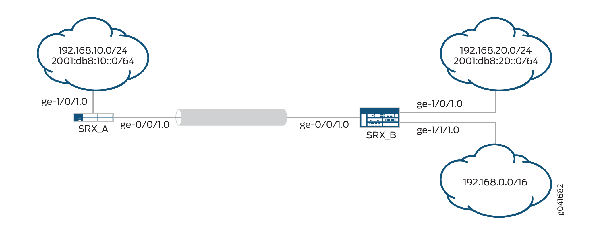
Overview
This example configures traffic selectors to allow traffic to flow between subnetworks on SRX_A and subnetworks on SRX_B.
Table 2 shows the traffic selectors for this example. Traffic selectors are configured under Phase 2 options.
SRX_A |
SRX_B |
||||
|---|---|---|---|---|---|
Traffic Selector Name |
Local IP |
Remote IP |
Traffic Selector Name |
Local IP |
Remote IP |
TS1-ipv6 |
2001:db8:10::0/64 |
2001:db8:20::0/64 |
TS1-ipv6 |
2001:db8:20::0/64 |
2001:db8:10::0/64 |
TS2-ipv4 |
192.168.10.0/24 |
192.168.0.0/16 |
TS2-ipv4 |
192.168.0.0/16 |
192.168.10.0/24 |
Flow-based processing of IPv6 traffic must be enabled with the mode flow-based configuration option at the [edit security
forwarding-options family inet6] hierarchy level.
Topology
In Figure 1, an IPv6 VPN tunnel carries both IPv4 and IPv6 traffic between the SRX_A and SRX_B devices. That is, the tunnel operates in both IPv4-in-IPv6 and IPv6-in-IPv6 tunnel modes.
Configuration
Configuring SRX_A
CLI Quick Configuration
To quickly configure this example, copy the
following commands, paste them into a text file, remove any line breaks,
change any details necessary to match your network configuration,
copy and paste the commands into the CLI at the [edit] hierarchy
level, and then enter commit from configuration mode.
set interfaces ge-0/0/1 unit 0 family inet6 address 2001:db8:2000::1/64
set interfaces st0 unit 1 family inet
set interfaces st0 unit 1 family inet6
set interfaces ge-1/0/1 unit 0 family inet address 192.168.10.1/24
set interfaces ge-1/0/1 unit 0 family inet6 address 2001:db8:10::0/64
set security ike proposal PSK-DH14-AES256-SHA256 authentication- method pre-shared-keys
set security ike proposal PSK-DH14-AES256-SHA256 dh-group group14
set security ike proposal PSK-DH14-AES256-SHA256 authentication- algorithm sha-256
set security ike proposal PSK-DH14-AES256-SHA256 encryption-algorithm aes-256-cbc
set security ike policy site-2-site mode main
set security ike policy site-2-site proposals PSK-DH14-AES256-SHA256
set security ike policy site-2-site pre-shared-key ascii-text "$ABC123"
set security ike gateway SRX_A-to-SRX_B ike-policy site-2-site
set security ike gateway SRX_A-to-SRX_B address 192.168.20.2
set security ike gateway SRX_A-to-SRX_B external-interface ge-0/0/1.0
set security ike gateway SRX_A-to-SRX_B local-address 192.168.10.1
set security ipsec proposal ESP-AES256-SHA256 protocol esp
set security ipsec proposal ESP-AES256-SHA256 authentication- algorithm hmac-sha-256-128
set security ipsec proposal ESP-AES256-SHA256 encryption-algorithm aes-256-cbc
set security ipsec policy site-2-site perfect-forward-secrecy keys group14
set security ipsec policy site-2-site proposals ESP-AES256-SHA256
set security ipsec vpn SRX_A-to-SRX_B bind-interface st0.1
set security ipsec vpn SRX_A-to-SRX_B ike ipsec-policy site-2-site
set security ipsec vpn SRX_A-to-SRX_B ike gateway SRX_A-to-SRX_B
set security ipsec vpn SRX_A-to-SRX_B traffic-selector TS1-ipv6 term term1 local-ip 2001:db8:10::0/64 remote-ip 2001:db8:20::0/64
set security ipsec vpn SRX_A-to-SRX_B traffic-selector TS2-ipv4 term term2 local-ip 192.168.10.0/24 remote-ip 192.168.0.0/16
set security forwarding-options family inet6 mode flow-based
set security zones security-zone trust host-inbound-traffic system-services all
set security zones security-zone trust host-inbound-traffic protocols all
set security zones security-zone trust interfaces ge-1/0/1.0
set security zones security-zone untrust host-inbound-traffic system-services ike
set security zones security-zone untrust interfaces ge-0/0/1.0
set security zones security-zone VPN interfaces st0.1
set security policies from-zone VPN to-zone trust policy 1 match source-address any
set security policies from-zone VPN to-zone trust policy 1 match destination-address any
set security policies from-zone VPN to-zone trust policy 1 match application any
set security policies from-zone VPN to-zone trust policy 1 then permit
set security policies from-zone trust to-zone VPN policy 1 match source-address any
set security policies from-zone trust to-zone VPN policy 1 match destination-address any
set security policies from-zone trust to-zone VPN policy 1 match application any
set security policies from-zone trust to-zone VPN policy 1 then permit
set security policies default-policy deny -all
Step-by-Step Procedure
The following example requires you to navigate various levels in the configuration hierarchy. For instructions on how to do that, see Using the CLI Editor in Configuration Mode in the CLI User Guide.
To configure traffic selectors:
Configure the external interface.
[edit interfaces]
user@host# set ge-0/0/1 unit 0 family inet6 address 2001:db8:2000::1/64
Configure the secure tunnel interface.
[edit interfaces]
user@host# set st0 unit 1 family inet
user@host# set st0 unit 1 family inet6
Configure the internal interface.
[edit interfaces]
user@host# set ge-1/0/1 unit 0 family inet address 192.168.10.1/24
user@host# set ge-1/0/1 unit 0 family inet6 address 2001:db8:10::0/64
Configure Phase 1 options.
[edit security ike proposal PSK-DH14-AES256-SHA256]
user@host# set authentication-method pre-shared-keys
user@host# set dh-group group14
user@host# set authentication-algorithm sha-256
user@host# set encryption-algorithm aes-256-cbc
[edit security ike policy site-2-site]
user@host# set mode main
user@host# set proposals PSK-DH14-AES256-SHA256
user@host# set pre-shared-key ascii-text "$ABC123"
[edit security ike gateway SRX_A-to-SRX_B]
user@host# set ike-policy site-2-site
user@host# set address 192.168.20.2
user@host# set external-interface ge-0/0/1.0
user@host# set local-address 192.168.10.1
Configure Phase 2 options.
[edit security ipsec proposal ESP-AES256-SHA256]
user@host# set protocol esp
user@host# set authentication-algorithm hmac-sha-256-128
user@host# set encryption-algorithm aes-256-cbc
[edit security ipsec policy site-2-site]
user@host# set perfect-forward-secrecy keys group14
user@host# set proposals ESP-AES256-SHA256
[edit security ipsec vpn SRX_A-to-SRX_B]
user@host# set bind-interface st0.1
user@host# set ike gateway SRX_A-to-SRX_B
user@host# set ike ipsec-policy site-2-site
user@host# set traffic-selector TS1-ipv6 term term1 local-ip 2001:db8:10::0/64 remote-ip 2001:db8:20::0/64
user@host# set traffic-selector TS2-ipv4 term term2 local-ip 192.168.10.0/24 remote-ip 192.168.0.0/16
Enable IPv6 flow-based forwarding.
[edit security forwarding-options]
user@host# set family inet6 mode flow-based
Configure security zones and the security policy.
[edit security zones security-zone trust]
user@host# set host-inbound-traffic  system-services all
user@host# set host-inbound-traffic  protocols all
user@host# set interfaces ge-1/0/1.0
[edit security zones security-zone untrust]
user@host# set host-inbound-traffic  system-services ike
user@host# set interfaces ge-0/0/1.0
[edit security zones security-zone VPN]
user@host# set interfaces st0.1
[edit security policies from-zone VPN to-zone trust ]
user@host# set policy 1 match source-address any
user@host# set policy 1 match destination-address any
user@host# set policy 1 match application any
user@host# set policy 1 then permit
[edit security policies from-zone trust to-zone VPN ]
user@host# set policy 1 match source-address any
user@host# set policy 1 match destination-address any
user@host# set policy 1 match application any
user@host# set policy 1 then permit
[edit security policies]
user@host# set default-policy deny-all
Results
From configuration mode, confirm your configuration
by entering the show interfaces, show security ike, show security ipsec, show security forwarding-options, show security zones, and show security policies commands. If the output does not display the intended configuration,
repeat the configuration instructions in this example to correct it.
[edit]
    user@host# show interfaces
    ge-0/0/1 {
        unit 0 {
            family inet6 {
                address 2001:db8:2000::1/64;
            }
        }
    }
    ge-1/0/1 {
        unit 0 {
            family inet {
                address 192.168.10.1/24;
            }
            family inet6 {
                address 10::1/64;
            }
        }
    }
    st0 {
        unit 1 {
            family inet;
            family inet6;
        }
    }
    [edit]
    user@host# show security ike
    proposal PSK-DH14-AES256-SHA256 {
        authentication-method pre-shared-keys;
        dh-group group14;
        authentication-algorithm sha-256;
        encryption-algorithm aes-256-cbc;
    }
    policy site-2-site {
        mode main;
        proposals PSK-DH14-AES256-SHA256;
            pre-shared-key ascii-text
        "$ABC123"; ## SECRET-DATA
    }
    gateway SRX_A-to-SRX_B {
        ike-policy site-2-site;
        address 192.168.20.2;
        external-interface ge-0/0/1.0;
        local-address 192.168.10.1;
    }
    [edit]
    user@host# show security ipsec
    proposal ESP-AES256-SHA256 {
        protocol esp;
        authentication-algorithm hmac-sha-256-128;
        encryption-algorithm aes-256-cbc;
    }
    policy site-2-site {
        perfect-forward-secrecy keys group14;
        proposals ESP-AES256-SHA256;
    }
    vpn SRX_A-to-SRX_B {
        bind-interface st0.1;
        ike {
            ipsec-policy site-2-site;
            gateway SRX_A-to-SRX_B;
        }
        traffic-selector TS1-ipv6 {
            local-ip 2001:db8:10::0/64;
            remote-ip 2001:db8:20::0/64;
        }
        traffic-selector TS2-ipv4 {
            local-ip 192.168.10.0/24;
            remote-ip 192.168.0.0/16;
        }
    }
    [edit]
    user@host# show security forwarding-options
    family {
        inet6 {
            mode flow-based;
        }
    }
    [edit]
    user@host# show security zones
    security-zone trust {
        host-inbound-traffic {
            system-services {
                all;
            }
            protocols {
                all;
            }
        }
        interfaces {
            ge-1/0/1.0;
        }
    }
    security-zone untrust {
        host-inbound-traffic {
            system-services {
                ike;
            }
        }
        interfaces {
            ge-0/0/1.0;
        }
    }
    security-zone VPN {
        interfaces {
            st0.1;
        }
    }
    [edit]
user@host# show security policies
    from-zone VPN to-zone trust {
        policy 1 {
            match {
                source-address any;
                destination-address any;
                application any;
            }
            then {
                permit;
            }
        }
    }
    from-zone trust to-zone VPN {
        policy 1 {
            match {
                source-address any;
                destination-address any;
                application any;
            }
            then {
                permit;
            }
        }
    }
If you are done configuring the device, enter commit from configuration mode.
Configuring SRX_B
CLI Quick Configuration
To quickly configure this example, copy the
following commands, paste them into a text file, remove any line breaks,
change any details necessary to match your network configuration,
copy and paste the commands into the CLI at the [edit] hierarchy
level, and then enter commit from configuration mode.
set interfaces ge-0/0/1 unit 0 family inet6 address 2001:db8:2000::2/64
set interfaces st0 unit 1 family inet
set interfaces st0 unit 1 family inet6
set interfaces ge-1/0/1 unit 0 family inet address 192.168.20.1/24
set interfaces ge-1/0/1 unit 0 family inet6 address 2001:db8:20::0/64
set interfaces ge-1/1/1 unit 0 family inet address 192.168.0.1/24
set security ike proposal PSK-DH14-AES256-SHA256 authentication-method pre-shared-keys
set security ike proposal PSK-DH14-AES256-SHA256 dh-group group14
set security ike proposal PSK-DH14-AES256-SHA256 authentication-algorithm sha-256
set security ike proposal PSK-DH14-AES256-SHA256 encryption-algorithm aes-256-cbc
set security ike policy site-2-site mode main
set security ike policy site-2-site proposals PSK-DH14-AES256-SHA256
set security ike policy site-2-site pre-shared-key ascii-text "$ABC123"
set security ike gateway SRX_B-to-SRX_A ike-policy site-2-site
set security ike gateway SRX_B-to-SRX_A address 192.168.10.1
set security ike gateway SRX_B-to-SRX_A external-interface ge-0/0/1.0
set security ike gateway SRX_B-to-SRX_A local-address 192.168.20.2
set security ipsec proposal ESP-AES256-SHA256 protocol esp
set security ipsec proposal ESP-AES256-SHA256 authentication-algorithm hmac-sha-256-128
set security ipsec proposal ESP-AES256-SHA256 encryption-algorithm aes-256-cbc
set security ipsec policy site-2-site perfect-forward-secrecy keys group14
set security ipsec policy site-2-site proposals ESP-AES256-SHA256
set security ipsec vpn SRX_B-to-SRX-A bind-interface st0.1
set security ipsec vpn SRX_B-to-SRX-A ike ipsec-policy site-2-site
set security ipsec vpn SRX_B-to-SRX-A ike gateway SRX_B-to-SRX_A
set security ipsec vpn SRX_B-to-SRX-A traffic-selector TS1-ipv6 local-ip 2001:db8:20::0/64 remote-ip 2001:db8:10::0/64
set security ipsec vpn SRX_B-to-SRX-A traffic-selector TS2-ipv4 local-ip 192.168.0.0/16 remote-ip 192.168.10.0/24
set security forwarding-options family inet6 mode flow-based
set security zones security-zone trust host-inbound-traffic system-services all
set security zones security-zone trust host-inbound-traffic protocols all
set security zones security-zone trust interfaces ge-1/0/1.0
set security zones security-zone trust interfaces ge-1/1/1.0
set security zones security-zone untrust host-inbound-traffic system-services ike
set security zones security-zone VPN interfaces st0.1
set security zones security-zone untrust interfaces ge-0/0/1.0
set security policies from-zone VPN to-zone trust policy 1 match source-address any
set security policies from-zone VPN to-zone trust policy 1 match destination-address any
set security policies from-zone VPN to-zone trust policy 1 match application any
set security policies from-zone VPN to-zone trust policy 1 then permit
set security policies from-zone trust to-zone VPN policy 1 match source-address any
set security policies from-zone trust to-zone VPN policy 1 match destination-address any
set security policies from-zone trust to-zone VPN policy 1 match application any
set security policies from-zone trust to-zone VPN policy 1 then permit
set security policies default-policy deny -all
Step-by-Step Procedure
The following example requires you to navigate various levels in the configuration hierarchy. For instructions on how to do that, see Using the CLI Editor in Configuration Mode in the CLI User Guide.
To configure traffic selectors:
Configure the external interface.
[edit interfaces]
user@host# set ge-0/0/1 unit 0 family inet6 address 2001:db8:2000::2/64
Configure the secure tunnel interface.
[edit interfaces]
user@host# set st0 unit 1 family inet
user@host# set st0 unit 1 family inet6
Configure the internal interfaces.
[edit interfaces]
user@host# set ge-1/0/1 unit 0 family inet address 192.168.20.1/24
user@host# set ge-1/0/1 unit 0 family inet6 address 2001:db8:20::0/64
user@host# set ge-1/1/1 unit 0 family inet address 192.168.0.1/24
Configure Phase 1 options.
[edit security ike proposal PSK-DH14-AES256-SHA256]
user@host# set authentication-method pre-shared-keys
user@host# set dh-group group14
user@host# set authentication-algorithm sha-256
user@host# set encryption-algorithm aes-256-cbc
[edit security ike policy site-2-site]
user@host# set mode main
user@host# set proposals PSK-DH14-AES256-SHA256
user@host# set pre-shared-key ascii-text "$ABC123"
[edit security ike gateway SRX_B-to-SRX_A]
user@host# set ike-policy site-2-site
user@host# set address 192.168.10.1
user@host# set external-interface ge-0/0/1.0
user@host# set local-address 192.168.20.2
Configure Phase 2 options.
[edit security ipsec proposal ESP-AES256-SHA256]
user@host# set protocol esp
user@host# set authentication-algorithm hmac-sha-256-128
user@host# set encryption-algorithm aes-256-cbc
[edit security ipsec policy site-2-site]
user@host# set perfect-forward-secrecy keys group14
user@host# set proposals ESP-AES256-SHA256
[edit security ipsec vpn SRX_B-to-SRX-A]
user@host# set bind-interface st0.1
user@host# set ike gateway SRX_B-to-SRX_A
user@host# set ike ipsec-policy site-2-site
user@host# set traffic-selector TS1-ipv6 local-ip 2001:db8:20::0/64 remote-ip 2001:db8:10::0/64
user@host# set traffic-selector TS2-ipv4 local-ip 192.168.0.0/16 remote-ip 192.168.10.0/24
Enable IPv6 flow-based forwarding.
[edit security forwarding-options]
user@host# set family inet6 mode flow-based
Configure security zones and the security policy.
[edit security zones security-zone trust]
user@host# set host-inbound-traffic  system-services all
user@host# set host-inbound-traffic  protocols all
user@host# set interfaces ge-1/0/1.0
[edit security zones security-zone untrust]
user@host# set host-inbound-traffic  system-services ike
user@host# set interfaces ge-0/0/1.0
[edit security zones security-zone VPN]
user@host# set interfaces st0.1
[edit security policies from-zone VPN to-zone trust ]
user@host# set policy 1 match source-address any
user@host# set policy 1 match destination-address any
user@host# set policy 1 match application any
user@host# set policy 1 then permit
[edit security policies from-zone trust to-zone VPN ]
user@host# set policy 1 match source-address any
user@host# set policy 1 match destination-address any
user@host# set policy 1 match application any
user@host# set policy 1 then permit
[edit security policies]
user@host# set default-policy deny-all
Results
From configuration mode, confirm your configuration
by entering the show interfaces, show security ike, show security ipsec, show security forwarding-options, show security zones, and show security policies commands. If the output does not display the intended configuration,
repeat the configuration instructions in this example to correct it.
[edit]
    user@host# show interfaces
    ge-0/0/1 {
        unit 0 {
            family inet6 {
                address 2001:db8:2000::2/64;
            }
        }
    }
    ge-1/0/1 {
        unit 0 {
            family inet {
                address 192.168.20.1/24;
            }
            family inet6 {
                address 2001:db8:20::0/64;
            }
        }
    }
    ge-1/1/1 {
        unit 0 {
            family inet {
                address 192.168.0.1/24;
            }
        }
    }
    st0 {
        unit 1 {
            family inet;
            family inet6;
        }
    }
    [edit]
    user@host# show security ike
    proposal PSK-DH14-AES256-SHA256 {
        authentication-method pre-shared-keys;
        dh-group group14;
        authentication-algorithm sha-256;
        encryption-algorithm aes-256-cbc;
    }
    policy site-2-site {
        mode main;
        proposals PSK-DH14-AES256-SHA256;
        pre-shared-key ascii-text "$ABC123"; ## SECRET-DATA
    }
    gateway SRX_B-to-SRX_A {
        ike-policy site-2-site;
        address 192.168.10.1;
        external-interface ge-0/0/1.0;
        local-address 192.168.20.2;
    }
    [edit]
    user@host# show security ipsec
    proposal ESP-AES256-SHA256 {
        protocol esp;
        authentication-algorithm hmac-sha-256-128;
        encryption-algorithm aes-256-cbc;
    }
    policy site-2-site {
        perfect-forward-secrecy keys group14;
        proposals ESP-AES256-SHA256;
    }
    vpn SRX_B-to-SRX-A {
        bind-interface st0.1;
        ike {
            ipsec-policy site-2-site;
            gateway SRX_B-to-SRX_A;
        }
        traffic-selector TS1-ipv6 {
            local-ip 2001:db8:20::0/64;
            remote-ip 2001:db8:10::0/64;
        }
        traffic-selector TS2-ipv4 {
            local-ip 192.168.0.0/16;
            remote-ip 192.168.10.0/24;
        }
    }
    [edit]
    user@host# show security forwarding-options
    family {
        inet6 {
            mode flow-based;
        }
    }
    [edit]
    user@host# show security zones
    security-zone trust {
        host-inbound-traffic {
            system-services {
                all;
            }
            protocols {
                all;
            }
        }
        interfaces {
            ge-1/0/1.0;
            ge-1/1/1.0;
        }
    }
    security-zone untrust {
        host-inbound-traffic {
            system-services {
                ike;
            }
        }
        interfaces {
            ge-0/0/1.0;
        }
    }
    security-zone VPN {
        interfaces {
            st0.1;
        }
    }
    [edit]
user@host# show security policies
    from-zone VPN to-zone trust {
        policy 1 {
            match {
                source-address any;
                destination-address any;
                application any;
            }
            then {
                permit;
            }
        }
    }
    from-zone trust to-zone VPN {
        policy 1 {
            match {
                source-address any;
                destination-address any;
                application any;
            }
            then {
                permit;
            }
        }
    }
If you are done configuring the device, enter commit from configuration mode.
Verification
Confirm that the configuration is working properly.
The sample outputs shown are on SRX-A.
Verifying IPsec Phase 2 Status
Purpose
Verify the IPsec Phase 2 status.
Action
From operational mode, enter the show security
ipsec security-associations command.
user@host> show security ipsec security-associations
  Total active tunnels: 3
  ID    Algorithm       SPI      Life:sec/kb  Mon lsys Port  Gateway
  <268173313 ESP:3des/ sha-256 3d75aeff 2984/ unlim -  root 500   2001:db8:2000::2
  >268173313 ESP:3des/ sha-256 a468fece 2984/ unlim -  root 500   2001:db8:2000::2
  <268173316 ESP:3des/ sha-256 417f3cea 3594/ unlim -  root 500   2001:db8:2000::2
  >268173316 ESP:3des/ sha-256 a4344027 3594/ unlim -  root 500   2001:db8:2000::2
From operational mode, enter the show security ipsec security-associations
detail command.
user@host> show security ipsec security-associations detail
  ID: 268173313 Virtual-system: root, VPN Name: SRX_A-to-SRX_B
  Local Gateway: 192.168.10.1, Remote Gateway: 2192.168.20.2
  Traffic Selector Name: TS1-ipv6
  Local Identity: ipv6(2001:db8:10::-2001:db8:10::ffff:ffff:ffff:ffff)
  Remote Identity: ipv6(2001:db8:20::-2001:db8:20::ffff:ffff:ffff:ffff)
  Version: IKEv1
    DF-bit: clear
    Bind-interface: st0.1

  Port: 500, Nego#: 0, Fail#: 0, Def-Del#: 0 Flag: c608b29
  Tunnel Down Reason: SA not initiated
    Direction: inbound, SPI: 3d75aeff, AUX-SPI: 0
                              , VPN Monitoring: -
    Hard lifetime: Expires in 2976 seconds
    Lifesize Remaining:  Unlimited
    Soft lifetime: Expires in 2354 seconds
    Mode: Tunnel(0 0), Type: dynamic, State: installed
    Protocol: ESP, Authentication: hmac-sha-256-128, Encryption: aes-256-cbc
    Anti-replay service: counter-based enabled, Replay window size: 64

    Direction: outbound, SPI: a468fece, AUX-SPI: 0
                              , VPN Monitoring: -
    Hard lifetime: Expires in 2976 seconds
    Lifesize Remaining:  Unlimited
    Soft lifetime: Expires in 2354 seconds
    Mode: Tunnel(0 0), Type: dynamic, State: installed
    Protocol: ESP, Authentication: hmac-sha-256-128, Encryption: aes-256-cbc
    Anti-replay service: counter-based enabled, Replay window size: 64

  ID: 268173316 Virtual-system: root, VPN Name: SRX_A-to-SRX_B
  Local Gateway: 192.168.10.1, Remote Gateway: 192.168.20.2
  Traffic Selector Name: TS2-ipv4
  Local Identity: ipv4(192.168.10.0-192.168.10.255)
  Remote Identity: ipv4(192.168.20.0-192.168.20.255)
  Version: IKEv1
    DF-bit: clear
    Bind-interface: st0.1

  Port: 500, Nego#: 0, Fail#: 0, Def-Del#: 0 Flag: c608b29
  Tunnel Down Reason: SA not initiated
    Direction: inbound, SPI: 417f3cea, AUX-SPI: 0
                              , VPN Monitoring: -
    Hard lifetime: Expires in 3586 seconds
    Lifesize Remaining:  Unlimited
    Soft lifetime: Expires in 2948 seconds
    Mode: Tunnel(0 0), Type: dynamic, State: installed
    Protocol: ESP, Authentication: hmac-sha-256-128, Encryption: aes-256-cbc
    Anti-replay service: counter-based enabled, Replay window size: 64

    Direction: outbound, SPI: a4344027, AUX-SPI: 0
                              , VPN Monitoring: -
    Hard lifetime: Expires in 3586 seconds
    Lifesize Remaining:  Unlimited
    Soft lifetime: Expires in 2948 seconds
    Mode: Tunnel(0 0), Type: dynamic, State: installed
    Protocol: ESP, Authentication: hmac-sha-256-128, Encryption: aes-256-cbc
    Anti-replay service: counter-based enabled, Replay window size: 64
Meaning
The show security ipsec security-associations command lists all active IKE Phase 2 SAs. If no SAs are listed,
there was a problem with Phase 2 establishment. Check the IKE policy
parameters and external interface settings in your configuration.
Phase 2 proposal parameters must match on the peer devices.
Verifying Traffic Selectors
Purpose
Verify negotiated traffic selectors on the secure tunnel interface.
Action
From operational mode, enter the show security
ipsec traffic-selector st0.1 command.
user@host> show security ipsec traffic-selector st0.1
Source IP                           		      Destination IP                                                          Interface   Tunnel-id         IKE-ID
2001:db8:10::-2001:db8:10::ffff:ffff:ffff:ffff  2001:db8:20::-2001:db8:20::ffff:ffff:ffff:ffff      st0.1       268173313      2001:db8:2000::1
192.168.10.0-192.168.10.255                          192.168.0.0-192.168.255.255                              st0.1       268173316      2001:db8:2000::1
192.168.10.0-192.168.10.255                          192.168.20.0-192.168.20.255                              st0.1       268173317      2001:db8:2000::1
Verifying Routes
Purpose
Verify active routes
Action
From operational mode, enter the show route command.
user@host> show route
inet.0: 24 destinations, 24 routes (24 active, 0 holddown, 0 hidden)
+ = Active Route, - = Last Active, * = Both

192.168.0.0/16        *[ARI-TS/5] 00:00:32
                    > via st0.1
2001:db8:20::0/64      *[ARI-TS/5] 00:00:34
                    > via st0.1
Meaning
The show route command lists active entries
in the routing tables. Routes to the remote IP address configured
in each traffic selector should be present with the correct st0 interface.
Platform-Specific ARI for Traffic Selectors Behavior
Use Feature Explorer to confirm platform and release support for specific features.
Use the following table to review platform-specific behaviors for your platforms.
|
Platform |
Difference |
|---|---|
|
MX Series |
|
Change History Table
Feature support is determined by the platform and release you are using. Use Feature Explorer to determine if a feature is supported on your platform.