Route-Based IPsec VPNs
A route-based VPN is a configuration in which an IPsec VPN tunnel created between two end points is referenced by a route that determines which traffic is sent through the tunnel based on a destination IP address.
Understanding Route-Based IPsec VPNs
With route-based VPNs, you can configure dozens of security policies to regulate traffic flowing through a single VPN tunnel between two sites, and there is just one set of IKE and IPsec SAs at work. Unlike policy-based VPNs, for route-based VPNs, a policy refers to a destination address, not a VPN tunnel. When Junos OS looks up a route to find the interface to use to send traffic to the packet’s destination address, it finds a route through a secure tunnel interface (st0.x). The tunnel interface is bound to a specific VPN tunnel, and the traffic is routed to the tunnel if the policy action is permit.
A secure tunnel (st0) interface supports only one IPv4 address
and one IPv6 address at the same time. This applies to all route-based
VPNs. The disable option is not supported on st0 interfaces.
A secure tunnel interface (st0) from st0.16000 to st0.16385 is reserved for Multinode High Availability and for HA control link encryption in Chassis Cluster. These interfaces are not user configurable interfaces. You can only use interfaces from st0.0 to st0.15999.
Examples of where route-based VPNs can be used:
There are overlapping subnets or IP addresses between the two LANs.
A hub-and-spoke VPN topology is used in the network, and spoke-to-spoke traffic is required.
Primary and backup VPNs are required.
A dynamic routing protocol (for example, OSPF, RIP, or BGP) is running across the VPN.
Configuring RIP demand circuits over point-to-multipoint VPN interfaces is not supported.
We recommend that you use route-based VPN when you want to configure VPN between multiple remote sites. Route-based VPN allows for routing between the spokes between multiple remote sites; it is easier to configure, monitor, and troubleshoot.
See Also
Example: Configuring a Route-Based VPN
This example shows how to configure a route-based IPsec VPN to allow data to be securely transferred between two sites.
Requirements
This example uses the following hardware:
-
Any SRX Series Firewall
- Updated and revalidated using vSRX Virtual Firewall on Junos OS Release 20.4R1.
Are you interested in getting hands-on experience with the topics and operations covered in this guide? Visit the IPsec Route-Based VPN demonstration in Juniper Networks Virtual Labs and reserve your free sandbox today! You’ll find the IPsec VPN Route-Based sandbox in the Security category.
Before you begin, read IPsec Overview.
Overview
In this example, you configure a route-based VPN on SRX1 and SRX2. Host1 and Host2 use the VPN to send traffic securely over the Internet between both hosts.
Figure 1 shows an example of a route-based VPN topology.
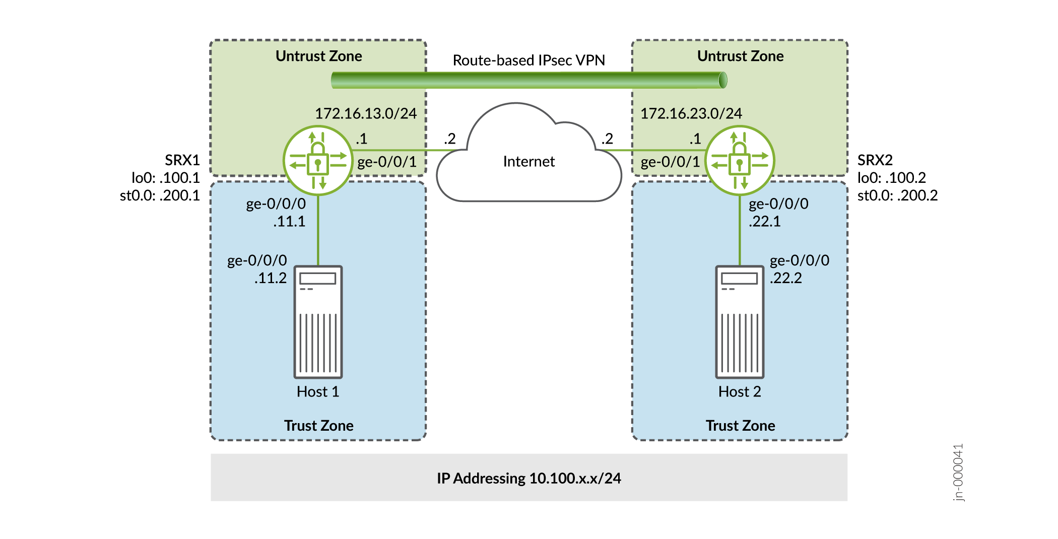
In this example, you configure interfaces, an IPv4 default route, and security zones. Then you configure IKE, IPsec, security policy, and TCP-MSS parameters. See Table 1 through Table 5 for specific configuration parameters used in this example.
|
Feature |
Name |
Configuration Parameters |
|---|---|---|
|
Interfaces |
ge-0/0/0.0 |
10.100.11.1/24 |
|
ge-0/0/1.0 |
172.16.13.1/24 |
|
|
st0.0 (tunnel interface) |
10.100.200.1/24 |
|
|
Static routes |
10.100.22.0/24 0.0.0.0/0 |
The next hop is st0.0. The next hop is 172.16.13.2. |
|
Security zones |
trust |
|
|
untrust |
|
|
|
vpn |
|
|
Feature |
Name |
Configuration Parameters |
|---|---|---|
|
Proposal |
standard |
|
|
Policy |
IKE-POL |
|
|
Gateway |
IKE-GW |
|
|
Feature |
Name |
Configuration Parameters |
|---|---|---|
|
Proposal |
standard |
|
|
Policy |
IPSEC-POL |
|
|
VPN |
VPN-to-Host2 |
|
|
Purpose |
Name |
Configuration Parameters |
|---|---|---|
|
The security policy permits traffic from the trust zone to the VPN zone. |
VPN-OUT |
|
|
The security policy permits traffic from the VPN zone to the trust zone. |
VPN-IN |
|
|
Purpose |
Configuration Parameters |
|---|---|
|
TCP-MSS is negotiated as part of the TCP three-way handshake and limits the maximum size of a TCP segment to better fit the MTU limits on a network. For VPN traffic, the IPsec encapsulation overhead, along with the IP and the frame overhead, can cause the resulting ESP packet to exceed the MTU of the physical interface, which causes fragmentation. Fragmentation increases bandwidth and the device resources. We recommend a value of 1350 as the starting point for most Ethernet-based networks with an MTU of 1500 or greater. You might need to experiment with different TCP-MSS values to obtain optimal performance. For example, you might need to change the value if any device in the path has a lower MTU, or if there is any additional overhead such as PPP or Frame Relay. |
MSS value: 1350 |
Configuration
- Configure Basic Network and Security Zone Information
- Configuring IKE
- Configuring IPsec
- Configuring Security Policies
- Configuring TCP-MSS
- Configuring SRX2
Configure Basic Network and Security Zone Information
CLI Quick Configuration
To quickly configure this section of the example for SRX1, copy the following
commands, paste them into a text file, remove any line breaks, change any
details necessary to match your network configuration, copy and paste the
commands into the CLI at the [edit] hierarchy level, and
then enter commit from configuration mode.
set interfaces ge-0/0/0 unit 0 family inet address 10.100.11.1/24
set interfaces ge-0/0/1 unit 0 family inet address 172.16.13.1/24
set interfaces lo0 unit 0 family inet address 10.100.100.1/32
set interfaces st0 unit 0 family inet address 10.100.200.1/24
set routing-options static route 10.100.22.0/24 next-hop st0.0
set routing-options static route 0.0.0.0/0 next-hop 172.16.13.2
set security zones security-zone trust host-inbound-traffic system-services all
set security zones security-zone trust interfaces ge-0/0/0.0
set security zones security-zone untrust host-inbound-traffic system-services ike
set security zones security-zone untrust host-inbound-traffic system-services ping
set security zones security-zone untrust interfaces ge-0/0/1.0
set security zones security-zone VPN host-inbound-traffic system-services ping
set security zones security-zone VPN interfaces st0.0
Step-by-Step Procedure
The following example requires you to navigate various levels in the configuration hierarchy. For instructions on how to do that, see the CLI User Guide.
To configure interface, static route, and security zone information:
-
Configure the interfaces.
[edit]
user@SRX1# set interfaces ge-0/0/0 unit 0 family inet address 10.100.11.1/24
user@SRX1# set interfaces ge-0/0/1 unit 0 family inet address 172.16.13.1/24
user@SRX1# set interfaces lo0 unit 0 family inet address 10.100.100.1/32
user@SRX1# set interfaces st0 unit 0 family inet address 10.100.200.1/24
-
Configure the static routes.
[edit]
user@SRX1# set routing-options static route 10.100.22.0/24 next-hop st0.0
user@SRX1# set routing-options static route 0.0.0.0/0 next-hop 172.16.13.2
-
Assign the Internet facing interface to the untrust security zone.
[edit security zones security-zone untrust]
user@SRX1# set interfaces ge-0/0/1.0
-
Specify the allowed system services for the untrust security zone.
[edit security zones security-zone untrust]
user@SRX1# set host-inbound-traffic system-services ike
user@SRX1# set host-inbound-traffic system-services ping
-
Assign the Host1 facing interface to the trust security zone.
[edit security zones security-zone trust]
user@SRX1# set interfaces ge-0/0/0.0
-
Specify the allowed system services for the trust security zone.
[edit security zones security-zone trust]
user@SRX1# set host-inbound-traffic system-services all
-
Assign the secure tunnel interface to the VPN security zone.
[edit security zones security-zone VPN]
user@SRX1# set interfaces st0.0
-
Specify the allowed system services for the VPN security zone.
[edit security zones security-zone VPN]
user@SRX1# set host-inbound-traffic system-services ping
Results
From configuration mode, confirm your configuration by entering the
show interfaces, show routing-options,
and show security zones commands. If the output does not
display the intended configuration, repeat the configuration instructions in
this example to correct it.
[edit]
user@SRX1# show interfaces
ge-0/0/0 {
    unit 0 {
        family inet {
            address 10.100.11.1/24;
        }
    }
}
ge-0/0/1 {
    unit 0 {
        family inet {
            address 172.16.13.1/24;
        }
    }
}
lo0 {
    unit 0 {
        family inet {
            address 10.100.100.1/32;
        }
    }
}
st0 {
    unit 0 {
        family inet {
            address 10.100.200.1/24;
        }
    }
}
[edit]
user@SRX1# show routing-options
static {
    route 10.100.22.0/24 next-hop st0.0;
    route 0.0.0.0/0 next-hop 172.16.13.2;
}
[edit]
user@SRX1# show security zones
security-zone trust {
    host-inbound-traffic {
        system-services {
            all;
        }
    }
    interfaces {
        ge-0/0/0.0;
    }
}
security-zone untrust {
    host-inbound-traffic {
        system-services {
            ike;
            ping;
        }
    }
    interfaces {
        ge-0/0/1.0;
    }
}
security-zone VPN {
    host-inbound-traffic {
        system-services {
            ping;
        }
    }
    interfaces {
        st0.0;
    }
}
Configuring IKE
CLI Quick Configuration
To quickly configure this section of the example for SRX1, copy the following
commands, paste them into a text file, remove any line breaks, change any
details necessary to match your network configuration, copy and paste the
commands into the CLI at the [edit] hierarchy level, and
then enter commit from configuration mode.
set security ike proposal standard authentication-method pre-shared-keys
set security ike policy IKE-POL mode main
set security ike policy IKE-POL proposals standard
set security ike policy IKE-POL pre-shared-key ascii-text $ABC123
set security ike gateway IKE-GW ike-policy IKE-POL
set security ike gateway IKE-GW address 172.16.23.1
set security ike gateway IKE-GW external-interface ge-0/0/1
Step-by-Step Procedure
The following example requires you to navigate various levels in the configuration hierarchy. For instructions on how to do that, see CLI User Guide.
To configure IKE:
-
Create the IKE proposal.
[edit security ike]
user@SRX1# set proposal standard
-
Define the IKE proposal authentication method.
[edit security ike proposal standard]
user@SRX1# set authentication-method pre-shared-keys
-
Create an IKE policy.
[edit security ike]
user@SRX1# set policy IKE-POL
-
Set the IKE policy mode.
[edit security ike policy IKE-POL]
user@SRX1# set mode main
-
Specify a reference to the IKE proposal.
[edit security ike policy IKE-POL]
user@SRX1# set proposals standard
-
Define the IKE policy authentication method.
[edit security ike policy IKE-POL]
user@SRX1# set pre-shared-key ascii-text $ABC123
-
Create an IKE gateway and define its external interface.
[edit security ike]
user@SRX1# set gateway IKE-GW external-interface ge-0/0/1
-
Define the IKE policy reference.
[edit security ike gateway IKE-GW]
user@SRX1# set ike-policy IKE-POL
-
Define the IKE gateway address.
[edit security ike gateway IKE-GW]
user@SRX1# set address 172.16.23.1
Results
From configuration mode, confirm your configuration by entering the
show security ike command. If the output does not
display the intended configuration, repeat the configuration instructions in
this example to correct it.
[edit]
user@SRX1# show security ike
proposal standard {
    authentication-method pre-shared-keys;
}
policy IKE-POL {
    mode main;
    proposals standard;
    pre-shared-key ascii-text "$ABC123"; ## SECRET-DATA
}
gateway IKE-GW {
    ike-policy IKE-POL;
    address 172.16.23.1;
    external-interface ge-0/0/1;
}
Configuring IPsec
CLI Quick Configuration
To quickly configure this section of the example for SRX1, copy the following
commands, paste them into a text file, remove any line breaks, change any
details necessary to match your network configuration, copy and paste the
commands into the CLI at the [edit] hierarchy level, and
then enter commit from configuration mode.
set security ipsec proposal standard
set security ipsec policy IPSEC-POL proposals standard
set security ipsec vpn VPN-to-Host2 bind-interface st0.0
set security ipsec vpn VPN-to-Host2 ike gateway IKE-GW
set security ipsec vpn VPN-to-Host2 ike ipsec-policy IPSEC-POL
set security ipsec vpn VPN-to-Host2 establish-tunnels immediately
Step-by-Step Procedure
The following example requires you to navigate various levels in the configuration hierarchy. For instructions on how to do that, see the CLI User Guide.
To configure IPsec:
-
Create an IPsec proposal.
[edit]
user@SRX1# set security ipsec proposal standard
-
Create the IPsec policy.
[edit security ipsec]
user@SRX1# set policy IPSEC-POL
-
Specify the IPsec proposal reference.
[edit security ipsec policy IPSEC-POL]
user@SRX1# set proposals standard
-
Specify the IKE gateway.
[edit security ipsec]
user@SRX1# set vpn VPN-to-Host2 ike gateway IKE-GW
-
Specify the IPsec policy.
[edit security ipsec]
user@host# set vpn VPN-to-Host2 ike ipsec-policy IPSEC-POL
-
Specify the interface to bind.
[edit security ipsec]
user@host# set vpn VPN-to-Host2 bind-interface st0.0
-
Configure the tunnel to establish immediately.
[edit security ipsec]
user@host# set vpn VPN-to-Host2 establish-tunnels immediately
Results
From configuration mode, confirm your configuration by entering the
show security ipsec command. If the output does not
display the intended configuration, repeat the configuration instructions in
this example to correct it.
[edit]
user@host# show security ipsec
proposal standard;
policy IPSEC-POL {
    proposals standard;
}
vpn VPN-to-Host2 {
    bind-interface st0.0;
    ike {
        gateway IKE-GW;
        ipsec-policy IPSEC-POL;
    }
    establish-tunnels immediately;
}
Configuring Security Policies
CLI Quick Configuration
To quickly configure security policies for SRX1, copy the following commands,
paste them into a text file, remove any line breaks, change any details
necessary to match your network configuration, copy and paste the commands
into the CLI at the [edit] hierarchy level, and then enter
commit from configuration mode.
set security address-book Host1 address Host1-Net 10.100.11.0/24
set security address-book Host1 attach zone trust
set security address-book Host2 address Host2-Net 10.100.22.0/24
set security address-book Host2 attach zone VPN
set security policies from-zone trust to-zone untrust policy default-permit match source-address any
set security policies from-zone trust to-zone untrust policy default-permit match destination-address any
set security policies from-zone trust to-zone untrust policy default-permit match application any
set security policies from-zone trust to-zone untrust policy default-permit then permit
set security policies from-zone trust to-zone VPN policy VPN-OUT match source-address Host1-Net
set security policies from-zone trust to-zone VPN policy VPN-OUT match destination-address Host2-Net
set security policies from-zone trust to-zone VPN policy VPN-OUT match application any
set security policies from-zone trust to-zone VPN policy VPN-OUT then permit
set security policies from-zone VPN to-zone trust policy VPN-IN match source-address Host2-Net
set security policies from-zone VPN to-zone trust policy VPN-IN match destination-address Host1-Net
set security policies from-zone VPN to-zone trust policy VPN-IN match application any
set security policies from-zone VPN to-zone trust policy VPN-IN then permit
Step-by-Step Procedure
The following example requires you to navigate various levels in the configuration hierarchy. For instructions on how to do that, see the CLI User Guide.
To configure security policies:
-
Create address book entries for the networks that will be used in the security policies.
[edit]
user@SRX1# set security address-book Host1 address Host1-Net 10.100.11.0/24
user@SRX1# set security address-book Host1 attach zone trust
user@SRX1# set security address-book Host2 address Host2-Net 10.100.22.0/24
user@SRX1# set security address-book Host2 attach zone VPN
-
Create a security policy to permit traffic from the trust zone to the untrust zone for traffic to the Internet.
[edit security policies from-zone trust to-zone untrust]
user@SRX1# set policy default-permit match source-address any
user@SRX1# set policy default-permit match destination-address any
user@SRX1# set policy default-permit match application any
user@SRX1# set policy default-permit then permit
-
Create a security policy to permit traffic from Host1 in the trust zone destined to Host2 in the VPN zone.
[edit security policies from-zone trust to-zone VPN]
user@SRX1# set policy VPN-OUT match source-address Host1-Net
user@SRX1# set policy VPN-OUT match destination-address Host2-Net
user@SRX1# set policy VPN-OUT match application any
user@SRX1# set policy VPN-OUT then permit
-
Create a security policy to permit traffic from Host2 in the VPN zone to Host1 in the trust zone.
[edit security policies from-zone VPN to-zone trust]
user@host# set policy VPN-IN match source-address Host2-Net
user@host# set policy VPN-IN match destination-address Host1-Net
user@host# set policy VPN-IN match application any
user@host# set policy VPN-IN then permit
Results
From configuration mode, confirm your configuration by entering the
show security address-book and show security
policies commands. If the output does not display the intended
configuration, repeat the configuration instructions in this example to
correct it.
[edit]
user@host# show security address-book
Host1 {
    address Host1-Net 10.100.11.0/24;
    attach {
        zone trust;
    }
}
Host2 {
    address Host2-Net 10.100.22.0/24;
    attach {
        zone VPN;
    }
}
user@host# show security policies
from-zone trust to-zone untrust {
    policy default-permit {
        match {
            source-address any;
            destination-address any;
            application any;
        }
        then {
            permit;
        }
    }
}
from-zone trust to-zone VPN {
    policy VPN-OUT {
        match {
            source-address Host1-Net;
            destination-address Host2-Net;
            application any;
        }
        then {
            permit;
        }
    }
}
from-zone VPN to-zone trust {
    policy VPN-IN {
        match {
            source-address Host2-Net;
            destination-address Host1-Net;
            application any;
        }
        then {
            permit;
        }
    }
}
Configuring TCP-MSS
CLI Quick Configuration
To quickly configure the TCP MSS for SRX1, copy the following commands, paste
them into a text file, remove any line breaks, change any details necessary
to match your network configuration, copy and paste the commands into the
CLI at the [edit] hierarchy level, and then enter
commit from configuration mode.
set security flow tcp-mss ipsec-vpn mss 1350
Step-by-Step Procedure
The following example requires you to navigate various levels in the configuration hierarchy. For instructions on how to do that, see the CLI User Guide.
To configure TCP-MSS information:
-
Configure the TCP-MSS information.
[edit]
user@SRX1# set security flow tcp-mss ipsec-vpn mss 1350
Results
From configuration mode, confirm your configuration by entering the
show security flow command. If the output does not
display the intended configuration, repeat the configuration instructions in
this example to correct it.
[edit]
user@SRX1# show security flow
tcp-mss {
    ipsec-vpn {
        mss 1350;
    }
}
If you are done configuring the device, enter commit from
configuration mode.
Configuring SRX2
CLI Quick Configuration
For reference, the configuration for the SRX2 is provided.
To quickly configure this section of the example, copy the following
commands, paste them into a text file, remove any line breaks, change any
details necessary to match your network configuration, copy and paste the
commands into the CLI at the [edit] hierarchy level, and
then enter commit from configuration mode.
set security ike proposal standard authentication-method pre-shared-keys
set security ike policy IKE-POL mode main
set security ike policy IKE-POL proposals standard
set security ike policy IKE-POL pre-shared-key ascii-text $ABC123
set security ike gateway IKE-GW ike-policy IKE-POL
set security ike gateway IKE-GW address 172.16.13.1
set security ike gateway IKE-GW external-interface ge-0/0/1
set security ipsec proposal standard
set security ipsec policy IPSEC-POL proposals standard
set security ipsec vpn VPN-to-Host1 bind-interface st0.0
set security ipsec vpn VPN-to-Host1 ike gateway IKE-GW
set security ipsec vpn VPN-to-Host1 ike ipsec-policy IPSEC-POL
set security ipsec vpn VPN-to-Host1 establish-tunnels immediately
set security address-book Host1 address Host1-Net 10.100.11.0/24
set security address-book Host1 attach zone VPN
set security address-book Host2 address Host2-Net 10.100.22.0/24
set security address-book Host2 attach zone trust
set security flow tcp-mss ipsec-vpn mss 1350
set security policies from-zone trust to-zone untrust policy default-permit match source-address any
set security policies from-zone trust to-zone untrust policy default-permit match destination-address any
set security policies from-zone trust to-zone untrust policy default-permit match application any
set security policies from-zone trust to-zone untrust policy default-permit then permit
set security policies from-zone trust to-zone VPN policy VPN-OUT match source-address Host2-Net
set security policies from-zone trust to-zone VPN policy VPN-OUT match destination-address Host1-Net
set security policies from-zone trust to-zone VPN policy VPN-OUT match application any
set security policies from-zone trust to-zone VPN policy VPN-OUT then permit
set security policies from-zone VPN to-zone trust policy VPN-IN match source-address Host1-Net
set security policies from-zone VPN to-zone trust policy VPN-IN match destination-address Host2-Net
set security policies from-zone VPN to-zone trust policy VPN-IN match application any
set security policies from-zone VPN to-zone trust policy VPN-IN then permit
set security zones security-zone trust host-inbound-traffic system-services all
set security zones security-zone trust interfaces ge-0/0/0.0
set security zones security-zone untrust host-inbound-traffic system-services ike
set security zones security-zone untrust host-inbound-traffic system-services ping
set security zones security-zone untrust interfaces ge-0/0/1.0
set security zones security-zone VPN host-inbound-traffic system-services ping
set security zones security-zone VPN interfaces st0.0
set interfaces ge-0/0/0 unit 0 family inet address 10.100.22.1/24
set interfaces ge-0/0/1 unit 0 family inet address 172.16.23.1/24
set interfaces lo0 unit 0 family inet address 10.100.100.2/32
set interfaces st0 unit 0 family inet address 10.100.200.2/24
set routing-options static route 10.100.11.0/24 next-hop st0.0
set routing-options static route 0.0.0.0/0 next-hop 172.16.23.2
Verification
Perform these tasks to confirm that the configuration is working properly:
- Verify the IKE Status
- Verify the IPsec Status
- Test Traffic Flow Across the VPN
- Review Statistics and Errors for an IPsec Security Association
Verify the IKE Status
Purpose
Verify the IKE status.
Action
From operational mode, enter the show security ike
security-associations command. After obtaining an index number
from the command, use the show security ike security-associations
index index_number detail command.
user@SRX1> show security ike security-associations
Index State Initiator cookie Responder cookie Mode Remote Address
1859340 UP b153dc24ec214da9 5af2ee0c2043041a Main 172.16.23.1
user@SRX1> show security ike security-associations index 1859340 detail
IKE peer 172.16.23.1, Index 1859340, Gateway Name: IKE-GW
Role: Responder, State: UP
Initiator cookie: b153dc24ec214da9, Responder cookie: 5af2ee0c2043041a
Exchange type: Main, Authentication method: Pre-shared-keys
Local: 172.16.13.1:500, Remote: 172.16.23.1:500
Lifetime: Expires in 23038 seconds
Reauth Lifetime: Disabled
IKE Fragmentation: Disabled, Size: 0
Remote Access Client Info: Unknown Client
Peer ike-id: 172.16.23.1
AAA assigned IP: 0.0.0.0
Algorithms:
Authentication : hmac-sha1-96
Encryption : 3des-cbc
Pseudo random function: hmac-sha1
Diffie-Hellman group : DH-group-2
Traffic statistics:
Input bytes : 1236
Output bytes : 868
Input packets: 9
Output packets: 5
Input fragmentated packets: 0
Output fragmentated packets: 0
IPSec security associations: 2 created, 2 deleted
Phase 2 negotiations in progress: 1
Negotiation type: Quick mode, Role: Responder, Message ID: 0
Local: 172.16.13.1:500, Remote: 172.16.23.1:500
Local identity: 172.16.13.1
Remote identity: 172.16.23.1
Flags: IKE SA is created
Meaning
The show security ike security-associations command lists
all active IKE SAs. If no SAs are listed, there was a problem with IKE
establishment. Check the IKE policy parameters and external interface
settings in your configuration.
If SAs are listed, review the following information:
-
Index—This value is unique for each IKE SA, which you can use in the
show security ike security-associations index detailcommand to get more information about the SA. -
Remote Address—Verify that the remote IP address is correct.
-
State
-
UP—The IKE SA has been established.
-
DOWN—There was a problem establishing the IKE SA.
-
-
Mode—Verify that the correct mode is being used.
Verify that the following are correct in your configuration:
-
External interfaces (the interface must be the one that receives IKE packets)
-
IKE policy parameters
-
Preshared key information
-
Proposal parameters (must match on both peers)
The show security ike security-associations index 1859340
detail command lists additional information about the security
association with an index number of 1859340:
-
Authentication and encryption algorithms used
-
lifetime
-
Traffic statistics (can be used to verify that traffic is flowing properly in both directions)
-
Role information
Troubleshooting is best performed on the peer using the responder role.
-
Initiator and responder information
-
Number of IPsec SAs created
-
Number of negotiations in progress
Verify the IPsec Status
Purpose
Verify the IPsec status.
Action
From operational mode, enter the show security ipsec
security-associations command. After obtaining an index number
from the command, use the show security ipsec security-associations
index index_number detail command.
user@SRX1> show security ipsec security-associations Total active tunnels: 1 Total Ipsec sas: 1 ID Algorithm SPI Life:sec/kb Mon lsys Port Gateway <131074 ESP:3des/sha1 912f9063 3403/ unlim - root 500 172.16.23.1 >131074 ESP:3des/sha1 71dbaa56 3403/ unlim - root 500 172.16.23.1
user@SRX1> show security ipsec security-associations index 131074 detail
ID: 131074 Virtual-system: root, VPN Name: VPN-to-Host2
Local Gateway: 172.16.13.1, Remote Gateway: 172.16.23.1
Local Identity: ipv4_subnet(any:0,[0..7]=0.0.0.0/0)
Remote Identity: ipv4_subnet(any:0,[0..7]=0.0.0.0/0)
Version: IKEv1
DF-bit: clear, Copy-Outer-DSCP Disabled, Bind-interface: st0.0
Port: 500, Nego#: 26, Fail#: 0, Def-Del#: 0 Flag: 0x600a29
Multi-sa, Configured SAs# 1, Negotiated SAs#: 1
Tunnel events:
Fri Jul 23 2021 10:46:34 -0700: IPSec SA negotiation successfully completed (23 times)
Fri Jul 23 2021 09:07:24 -0700: IKE SA negotiation successfully completed (3 times)
Thu Jul 22 2021 16:34:17 -0700: Negotiation failed with INVALID_SYNTAX error (3 times)
Thu Jul 22 2021 16:33:50 -0700: Tunnel configuration changed. Corresponding IKE/IPSec SAs are deleted (1 times)
Thu Jul 22 2021 16:23:49 -0700: IPSec SA negotiation successfully completed (2 times)
Thu Jul 22 2021 15:34:12
: IPSec SA delete payload received from peer, corresponding IPSec SAs cleared (1 times)
Thu Jul 22 2021 15:33:25 -0700: IPSec SA negotiation successfully completed (1 times)
Thu Jul 22 2021 15:33:25
: Tunnel is ready. Waiting for trigger event or peer to trigger negotiation (1 times)
Thu Jul 22 2021 15:33:25 -0700: External interface's address received. Information updated (1 times)
Thu Jul 22 2021 15:33:25 -0700: Bind-interface's zone received. Information updated (1 times)
Thu Jul 22 2021 10:34:55 -0700: IKE SA negotiation successfully completed (1 times)
Thu Jul 22 2021 10:34:46 -0700: No response from peer. Negotiation failed (16 times)
Direction: inbound, SPI: 912f9063, AUX-SPI: 0
, VPN Monitoring: -
Hard lifetime: Expires in 3302 seconds
Lifesize Remaining: Unlimited
Soft lifetime: Expires in 2729 seconds
Mode: Tunnel(0 0), Type: dynamic, State: installed
Protocol: ESP, Authentication: hmac-sha1-96, Encryption: 3des-cbc
Anti-replay service: counter-based enabled, Replay window size: 64
Direction: outbound, SPI: 71dbaa56, AUX-SPI: 0
, VPN Monitoring: -
Hard lifetime: Expires in 3302 seconds
Lifesize Remaining: Unlimited
Soft lifetime: Expires in 2729 seconds
Mode: Tunnel(0 0), Type: dynamic, State: installed
Protocol: ESP, Authentication: hmac-sha1-96, Encryption: 3des-cbc
Anti-replay service: counter-based enabled, Replay window size: 64
Meaning
The output from the show security ipsec
security-associations command lists the following
information:
-
The ID number is 131074. Use this value with the
show security ipsec security-associations indexcommand to get more information about this particular SA. -
There is one IPsec SA pair using port 500, which indicates that no NAT-traversal is implemented. (NAT-traversal uses port 4500 or another random high-number port.)
-
The SPIs, lifetime (in seconds), and usage limits (or lifesize in KB) are shown for both directions. The 3403/ unlim value indicates that the lifetime expires in 3403 seconds, and that no lifesize has been specified, which indicates that it is unlimited. Lifetime can differ from lifetime, as IPsec is not dependent on IKE after the VPN is up.
-
VPN monitoring is not enabled for this SA, as indicated by a hyphen in the Mon column. If VPN monitoring is enabled, U indicates that monitoring is up, and D indicates that monitoring is down.
-
The virtual system (vsys) is the root system, and it always lists 0.
The output from the show security ipsec security-associations index
131074 detail command lists the following information:
-
The local identity and remote identity make up the proxy ID for the SA.
A proxy ID mismatch is one of the most common causes for a IPsec failure. If no IPsec SA is listed, confirm that IPsec proposals, including the proxy ID settings, are correct for both peers. For route-based VPNs, the default proxy ID is local=0.0.0.0/0, remote=0.0.0.0/0, and service=any. Issues can occur with multiple route-based VPNs from the same peer IP. In this case, a unique proxy ID for each IPsec SA must be specified. For some third-party vendors, the proxy ID must be manually entered to match.
-
Another common reason for IPsec failure is not specifying the ST interface binding. If IPsec cannot complete, check the kmd log or set trace options.
Test Traffic Flow Across the VPN
Purpose
Verify the traffic flow across the VPN.
Action
Use the ping command from the Host1 device to test traffic
flow to Host2.
user@Host1> ping 10.100.22.1 rapid count 100
PING 10.100.22.1 (10.100.22.1): 56 data bytes
!!!!!!!!!!!!!!!!!!!!!!!!!!!!!!!!!!!!!!!!!!!!!!!!!!!!!!!!!!!!!!!!!!!!!!!!!!!!!!!!!!!!!!!!!!!!!!!!!!!!
--- 10.100.22.1 ping statistics ---
100 packets transmitted, 100 packets received, 0% packet loss
round-trip min/avg/max/stddev = 3.146/3.824/6.193/0.402 ms
Meaning
If the ping command fails from Host1, there might be a
problem with the routing, security policies, end host, or encryption and
decryption of ESP packets.
Review Statistics and Errors for an IPsec Security Association
Purpose
Review ESP and authentication header counters and errors for an IPsec security association.
Action
From operational mode, enter the show security ipsec statistics index
index_number command, using the index
number of the VPN for which you want to see statistics.
user@SRX1> show security ipsec statistics index 131074
ESP Statistics:
  Encrypted bytes:            13600
  Decrypted bytes:             8400
  Encrypted packets:            100
  Decrypted packets:            100
AH Statistics:
  Input bytes:                    0
  Output bytes:                   0
  Input packets:                  0
  Output packets:                 0
Errors:
  AH authentication failures: 0, Replay errors: 0
  ESP authentication failures: 0, ESP decryption failures: 0
  Bad headers: 0, Bad trailers: 0
You can also use the show security ipsec statistics command
to review statistics and errors for all SAs.
To clear all IPsec statistics, use the clear security ipsec
statistics command.
Meaning
If you see packet loss issues across a VPN, run the show security
ipsec statistics or show security ipsec statistics
detail command several times to confirm if the encrypted and
decrypted packet counters are incrementing. Look in the command output for
any incrementing error counters.