Forward Error Correction (FEC) and Bit Error Rate (BER)
Optical transport network (OTN) interfaces use pre-forward error correction (pre-FEC) bit error rate (BER) for monitoring the condition of an OTN link. Use this topic to understand more about how OTN links are monitored and the supported FEC modes on devices.
Overview
Optical interfaces on PTX Series support monitoring the condition of an optical link by using the pre-forward error correction (pre-FEC) bit error rate (BER). The following PICs support pre-FEC BER monitoring:
P1-PTX-2-100G-WDM
P2-100GE-OTN
P1-PTX-24-10G-W-SFPP
The PICs use forward error correction (FEC) to correct bit errors in the received data. As long as the pre-FEC BER is below the FEC limit, all bit errors are successfully identified and corrected and, therefore, no packet loss occurs. The system monitors the pre-FEC BER on each port. This gives an early warning of link degradation. By configuring an appropriate pre-FEC BER threshold and interval, you enable the PIC to take preemptive action before the FEC limit is reached. If you combine the pre-FEC BER threshold logic with MPLS fast reroute, then you can prevent or minimize packet loss.
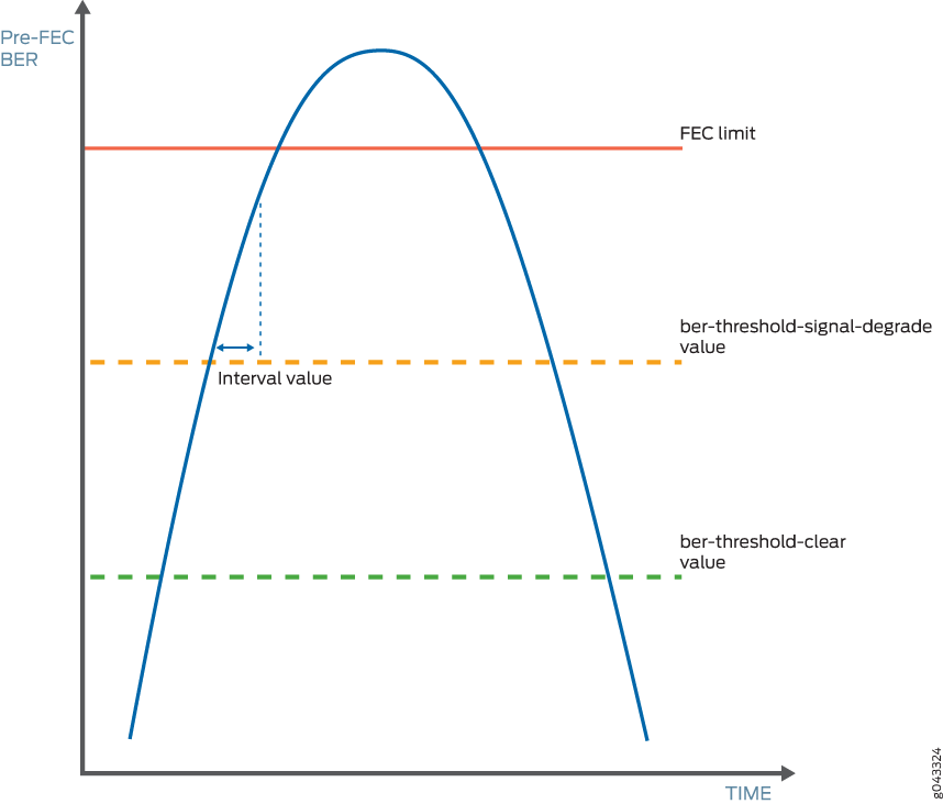
You must specify both the signal degradation threshold (ber-threshold-signal-degrade) and the interval (interval) for the interface. The threshold defines the BER criteria for a signal degrade condition and the interval defines the minimum duration over which the BER must exceed the threshold before an alarm is raised. The relationship between the threshold and the interval is illustrated in Figure 1. After an alarm is raised, if the BER returns to a level below the threshold clear value (ber-threshold-clear), the alarm is cleared.
With pre-FEC BER monitoring enabled, when the configured pre-FEC BER signal degrade threshold is reached, the PIC stops forwarding packets to the remote interface and raises an interface alarm. Ingress packets continue to be processed. If pre-FEC BER monitoring is used with MPLS fast reroute or another link protection method, then traffic is rerouted to a different interface.
You can also configure backward fast reroute to insert the local pre-FEC status into transmitted optical frames, notifying the remote interface of signal degradation. The remote interface can use the information to reroute traffic to a different interface. If you use pre-FEC BER monitoring together with backward fast reroute, then notification of signal degradation and rerouting of traffic occurs in less time than that required through a Layer 3 protocol.
Include the signal-degrade-monitor-enable and backward-frr-enable statements at the [edit interfaces interface-name otn-options preemptive-fast-reroute] hierarchy
level to enable pre-FEC BER monitoring and backward fast reroute.
When you configure pre-FEC BER signal degrade monitoring,
we recommend that you configure both the signal-degrade-monitor-enable and the backward-frr-enable statements.
You can also configure the pre-FEC BER thresholds that raise or clear a signal degrade alarm and the time interval for the thresholds. If the BER thresholds and interval are not configured, the default values are used.
When a received signal degrade alarm is active and backward fast reroute is enabled, a specific flag is inserted into the trasmitted optics overhead. The remote PIC at the opposite end of the link monitors the optics overhead, thus enabling both ends to initiate traffic rerouting in the event of a signal degrade condition. When the signal degrade condition is cleared, the overhead flag is returned to a normal state.
The pre-FEC BER signal degrade threshold value defines a specific amount of system margin relative to the BER correction limit (or FEC limit) of the PIC’s receive FEC decoder. Each PIC has a set FEC limit—it is intrinsic to the FEC decoder implementation.
The examples below use Q2-factor measurements (also known as Q-factor). Q2-factor is expressed in units of decibels relative to a Q2-factor of zero (dBQ). Q2-factor enables you to describe system margin in linear terms in contrast to BER values, which are nonlinear in nature. After you determine the thresholds, you must convert the threshold values from Q2-factor to BER to enter them in the CLI by using scientific notation. BER can be converted to Q2-factor by using the following equation:
Q2-factor = 20 * log10 (sqrt(2) * erfcinv(2 * BER))
To convert between Q2-factor and BER in a spreadsheet program, you can approximate the values by using the following formulas:
To calculate Q2-factor:
= 20 * LOG10(–NORMSINV(BER))
To calculate BER:
= 1 – NORMSDIST(10^(0.05 * Q2-factor))
Include the ber-threshold-signal-degrade, ber-threshold-clear, and interval statements at the [edit interfaces interface-name otn-options signal-degrade] hierarchy
level to configure the BER thresholds and time interval.
Configuring a high BER threshold for signal degradation and a long interval might cause the internal counter register to be saturated. Such a configuration is ignored by the router, and the default values are used instead. A system log message is logged for this error.
Signal Degrade and Clear Threshold Values for PICs
Table 1 shows the relationship between the fixed FEC limit, the configurable signal degrade threshold, and the configurable clear threshold for different PICs. In this example, approximately 1 dBQ of system margin has been set between the FEC limit, signal degrade threshold, and clear threshold.
|
PIC |
FEC Type |
FEC Limit |
Signal Degrade Threshold |
Clear Threshold |
|||
|---|---|---|---|---|---|---|---|
| Q2-Factor | BER | Q2-Factor | BER | Q2-Factor | BER | ||
|
P1-PTX-2-100G-WDM |
SD-FEC |
6.7 dBQ |
1.5E–2 |
7.7 dBQ |
7.5E–3 |
8.7 dBQ |
3.0E–3 |
|
P2-100GE-OTN |
G.709 GFEC |
11.5 dBQ |
8.0E–5 |
12.5 dBQ |
1.1E–5 |
13.5 dBQ |
1.0E–6 |
|
P1-PTX-24-10G-W-SFPP |
G.975.1 I.4 (UFEC) |
9.1 dBQ |
2.2E–3 |
10.1 dBQ |
6.9E–4 |
11.1 dBQ |
1.6E–4 |
|
G.975.1 I.7 (EFEC) |
9.6 dBQ |
1.3E–3 |
10.6 dBQ |
3.6E–4 |
11.6 dBQ |
7.5E–5 |
|
|
G.709 GFEC |
11.5 dBQ |
8.0E–5 |
12.5 dBQ |
1.1E–5 |
13.5 dBQ |
1.0E–6 |
|
To adjust the signal degrade threshold, you must first decide on a new system margin target and then calculate the respective BER value (using the equation to convert from Q2-factor to BER). Table 2 shows the values if 3 dBQ of system margin relative to the FEC limit is required for the signal degrade threshold (while maintaining the clear threshold at 1 dBQ relative to the signal degrade threshold).
The choice of system margin is subjective, as you might want to optimize your thresholds based on different link characteristics and fault tolerance and stability objectives. For guidance about configuring pre-FEC BER monitoring and BER thresholds, contact your Juniper Networks representative.
|
PIC |
FEC Type |
FEC Limit |
Signal Degrade Threshold |
Clear Threshold |
|||
|---|---|---|---|---|---|---|---|
| Q2-Factor | BER | Q2-Factor | BER | Q2-Factor | BER | ||
|
P1-PTX-2-100G-WDM |
SD-FEC |
6.7 dBQ |
1.5E–2 |
9.7 dBQ |
1.1E–3 |
10.7 dBQ |
2.9E–4 |
|
P2-100GE-OTN |
G.709 GFEC |
11.5 dBQ |
8.0E–5 |
14.5 dBQ |
4.9E–8 |
15.5 dBQ |
1.1E–9 |
|
P1-PTX-24-10G-W-SFPP |
G.975.1 I.4 (UFEC) |
9.1 dBQ |
2.2E–3 |
12.1 dBQ |
2.8E–5 |
13.1 dBQ |
3.1E–6 |
|
G.975.1 I.7 (EFEC) |
9.6 dBQ |
1.3E–3 |
12.6 dBQ |
1.1E–5 |
13.6 dBQ |
9.1E–7 |
|
|
G.709 GFEC |
11.5 dBQ |
8.0E–5 |
14.5 dBQ |
4.8E–8 |
15.5 dBQ |
1.1E–9 |
|
Supported Forward Error Correction Modes
This section describes FEC modes supported on different routers at the [edit
interfaces interface-name otn-options] level.
MX Series Routers
|
Line Card |
FEC Mode |
Port Speed |
|---|---|---|
|
|
10G |
|
|
|
10G and 100G (GFEC only) |
|
|
|
10G |
|
|
|
100G (GFEC only) |
|
|
|
100G |
PTX Series Routers
|
Line Card |
FEC Mode | Port Speed |
|---|---|---|
| P1-PTX-24-10G-W-SFPP |
(gfec | efec | none | ufec) |
10G |
| P2-10G-40G-QSFPP |
(gfec | efec | none | ufec) |
10G |
| P2-100GE-OTN |
(gfec | none) |
100G (GFEC only) |
| P1-PTX-2-100G-WDM |
(gfec-sdfec) |
100G |
| PTX-5-100G-WDM |
(gfec | sdfec) |
100G |
See Also
Supported Forward Error Correction Modes on PTX Series Routers
Table 6 lists the FEC modes that are supported
on PTX Series routers at the [edit interfaces interface-name otn-options] hierarchy level.
Line Card |
FEC Mode |
Port Speed |
Junos Version |
|---|---|---|---|
|
10G |
12.1X48, 12.3, 13.2 (PTX5000)13.2R2 (PTX3000) |
|
|
10G |
14.1R2 (PTX5000)15.1F6 (PTX3000) |
|
|
100G (GFEC only) |
14.1 |
|
|
100G |
13.2 (PTX5000)13.3 (PTX3000) |
|
|
100G |
15.1F6 |
See Also
Supported Forward Error Correction Modes on ACX6360 Router
Table 7 lists the FEC modes that are supported
on ACX6360 routers at the [edit interfaces interface-name optics-options] hierarchy
level.
FEC Mode |
Modulation Format |
Port Speed |
Junos Version |
|---|---|---|---|
|
QPSK |
100G |
18.3R1 |
|
QPSK |
100G |
18.3R1 |
|
8-QAM |
200G |
18.3R1 |
|
16-QAM |
200G |
18.3R1 |
See Also
Supported FEC Modes on ACX5448-D Router
Table 8 lists the forward error
correction (FEC) modes that are supported on ACX5448-D routers. You
can configure the FEC modes at the [edit interfaces interface-name optics-options] hierarchy level.
FEC Mode |
Modulation Format |
Port Speed |
Junos OS |
|---|---|---|---|
|
QPSK |
100 Gbps |
19.2R1-S1 |
|
QPSK |
100 Gbps |
19.2R1-S1 |
|
QPSK |
100 Gbps |
19.2R1-S1 |
|
8-QAM |
200 Gbps |
19.2R1-S1 |
|
16-QAM |
200 Gbps |
19.2R1-S1 |
See Also
Change History Table
Feature support is determined by the platform and release you are using. Use Feature Explorer to determine if a feature is supported on your platform.