QFX10016 System Overview
QFX10016 Hardware Overview
The Juniper Networks QFX10016 modular switch builds a strong underlay foundation for flexible, high-performance, standards-based fabrics and routing that improve network reliability and agility. The largest of the QFX10000 line of switches, the QFX10016 can provide 96 Tbps of throughput and 32 Bpps of forwarding capacity in a 21 rack unit (21 U) chassis. The QFX10016 has 16 slots for line cards that allow for a smooth transition from 10-Gigabit Ethernet and 40-Gigabit Ethernet networks to 100-Gigabit Ethernet high-performance networks. Table 1 shows the supported port densities.
|
Port Density |
Maximum |
|---|---|
|
10-Gigabit Ethernet |
2304 |
|
40-Gigabit Ethernet |
576 |
|
100-Gigabit Ethernet |
480 |
The QFX10016 can be deployed in various network designs and fabrics, including:
-
Layer 3 fabrics
-
Juniper Networks MC-LAG for Layer 2 and 3 networks
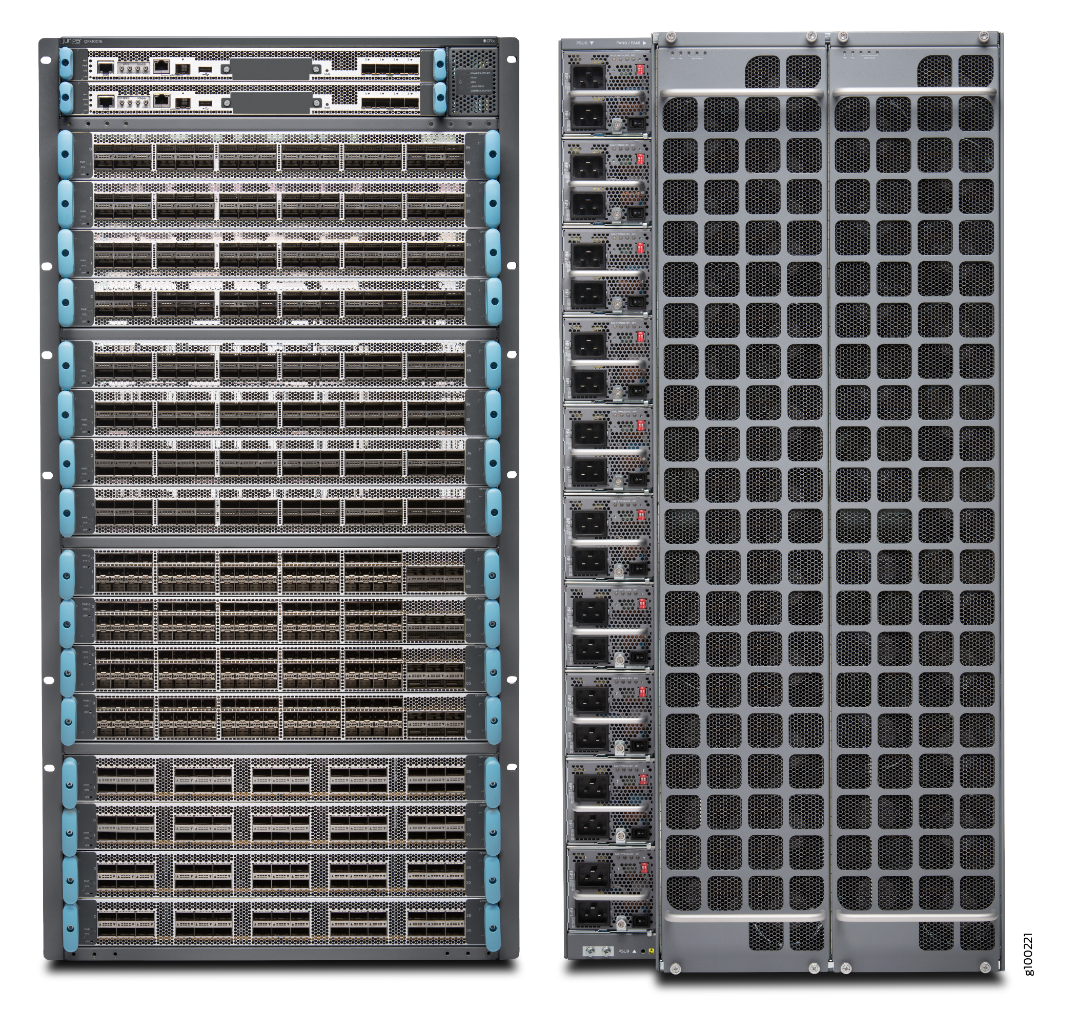
The QFX10016 is available in both base and redundant configurations for both AC and DC operation. All systems feature front-to-back airflow. This airflow is also know as airflow out (AFO).
Figure 1 shows a front and rear view of the QFX10016.
- Benefits of QFX10000 Modular Chassis Switches
- Chassis Description
- Routing and Control Board
- Line Cards
- Switch Interface Boards
- Cooling System
- Power Supplies
- Software
Benefits of QFX10000 Modular Chassis Switches
| System throughput |
The Juniper Networks® QFX10000 line of modular switches delivers up to 96 Tbps of system throughput to meet the rapid and ongoing traffic growth in data center, campus, and routing environments. Industry-leading scale and density on the QFX10000 modular switches redefine per-slot economics, enabling you to do more with less while simplifying network design and reducing operating expenditures. |
| Logical scale |
The QFX10000 modular switches deliver the highest Layer 2 / Layer 3 scale with up to 1 million MAC addresses, 2 million host routes, and 2 million FIB. The system also supports deep buffers with up to 100ms packet buffering per port. Virtual output Queue (VoQ) based architecture prevents head-of-line blocking. |
| Network architectures |
The QFX10000 line can be deployed in a number of different network designs and fabrics, including IP fabrics and EVPN-VXLAN overlays for Layer 2 and Layer 3 networks, along with support for DC edge and DCI use cases, giving customers complete architectural flexibility. Additionally, the open architecture ensures that customers can innovate on top of Juniper Networks Junos® operating system to accelerate the pace of innovation. |
Chassis Description
The QFX10016 is 21 U tall. Two QFX10016 chassis can fit in a standard 42 U rack with adequate cooling and power. All key QFX10016 components are field-replaceable units (FRUs). Figure 2 illustrates the key components visible from the front and rear of the chassis., Figure 3 illustrates the components that are visible from the rear of the chassis, and Figure 4 illustrates the components that are internal to the chassis.
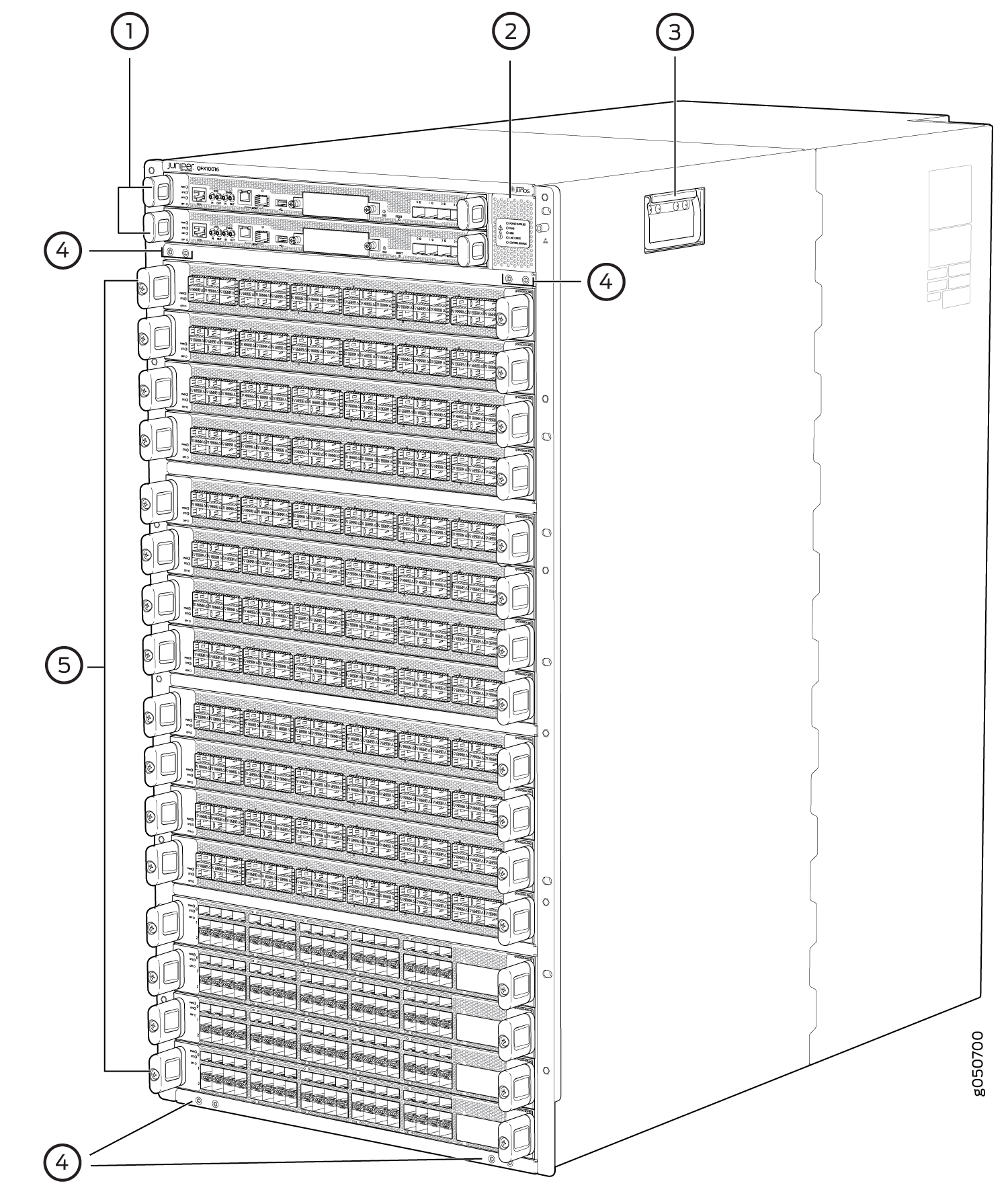
1 — RCBs slots 0 and 1 (numbered top to bottom) | 4 — Installation holes for the front panel |
2 — Status LED panel | 5 — Line card slots 0 to 15 (numbered top to bottom) |
3 — Handles |
Some chassis ship with an enhanced power bus to support the power needs of higher wattage line cards. Chassis with the enhanced power bus have a modified Status Panel (see QFX10000 Status Panel).
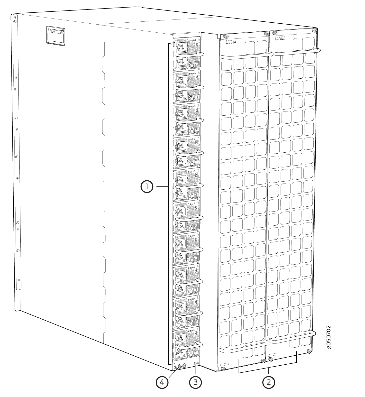
1 — AC or DC power supplies slots 0 to 9 (numbered top to bottom) | 3 — ESD point |
2 — Fan trays with redundant fans | 4 — Protective earthing terminal |
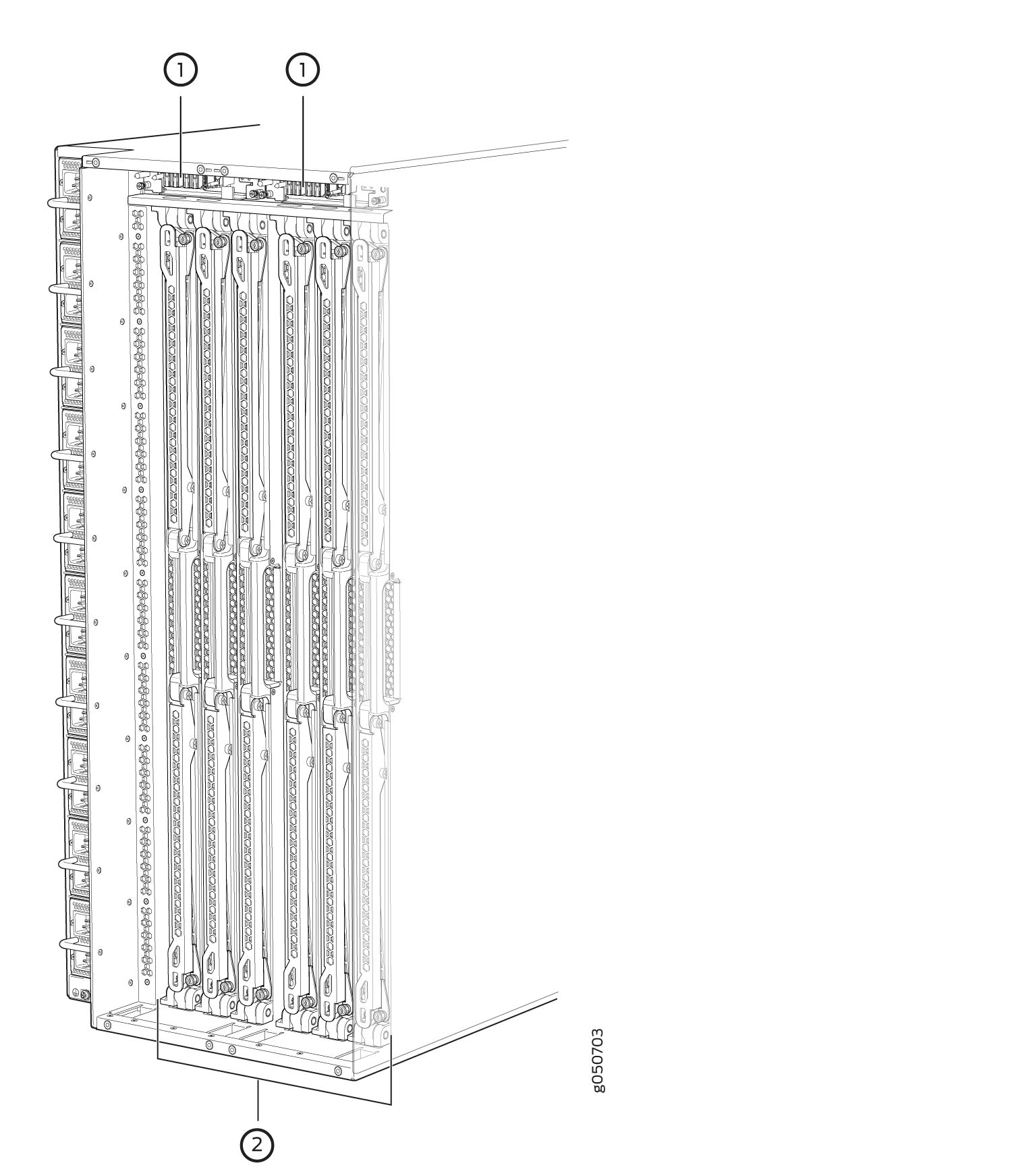
1 — Fan tray controllers slots 0 and 1 (numbered left to right) | 2 — Switch Interface Boards (SIBs) slots 0 to 5 (numbered left to right) |
See QFX10016 Chassis Physical Specifications and QFX10000 Field-Replaceable Units.
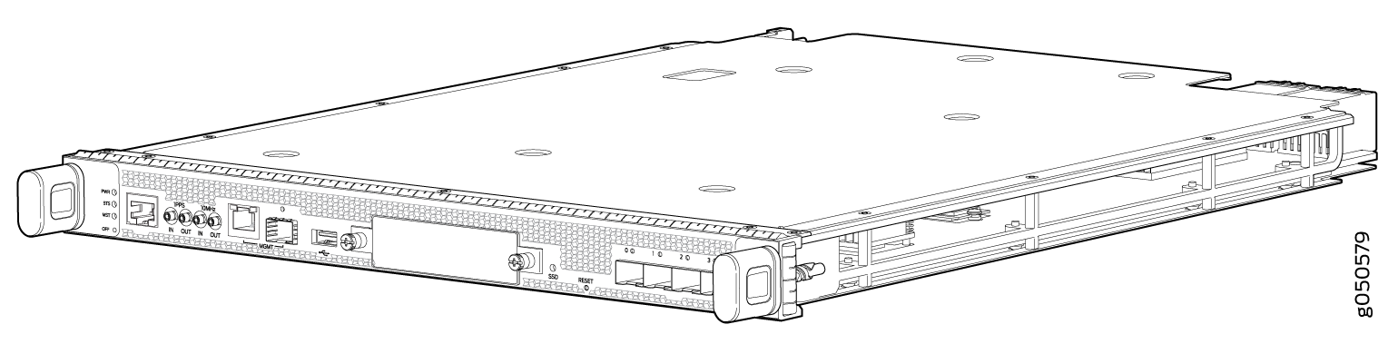
Routing and Control Board
The routing and control board (RCB) (see Figure 5) contains a Routing Engine and is responsible for the system management and system control in QFX10016. See QFX10000 Routing and Control Board Description. RCBs are FRUs that are installed in the front of the chassis in the slots labeled CB0 and CB1. The base configuration has a single RCB; the fully-redundant configuration has two RCBs. The RCB also contains Precision Time Protocol (PTP) ports and four Media Access Control Security (MACsec) capable ports. See QFX10016 Components and Configurations. The base configuration has a single RCB; the fully redundant configuration has two RCBs.
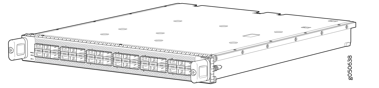
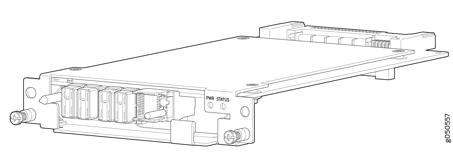
Line Cards
The QFX10016 features 16 horizontal line card slots and supports line rate for each line card. The line cards combine a Packet Forwarding Engine (PFE) and Ethernet interfaces enclosed in a single assembly. The QFX10000 line card architecture is based on a number of identical, independent PFE slices, each with 500 Gbps full-duplex throughput. Line cards are FRUs that can be installed in the line card slots labeled 0 through 15 (top to bottom) on the front of the switch chassis. All line cards are hot-removable and hot-insertable.
Five line cards are available for the QFX10016:
-
QFX10000-36Q–provides 36 ports of 40-gigabit QSFP+. Twelve ports are designed to be 100-Gigabit capable using QSFP28. Each of the 40-Gigabit QSFP+ can be configured as either a native 40-Gigabit port or four 10-Gigabit ports using a breakout cable. With breakout cables, the line card supports a maximum of 144 logical 10-Gigabit Ethernet ports.
-
QFX10000-30C–provides 30 ports of either 100-gigabit or 40-gigabit QSFP28. The ports autodetect the type of transceiver installed and set the configuration to the appropriate speed. Each of the 40-gigabit ports can be configured as either a native 40-gigabit port or four 10-gigabit ports using a breakout cable. With breakout cables, the line card supports a maximum of 96 logical 10-Gigabit Ethernet ports.
-
QFX10000-30C-M–provides 30 ports of either 100-gigabit or 40-gigabit QSFP28 that support MACsec security features.
-
QFX10000-60S-6Q–provides 60 SFP+ ports that can be configured for either 1-gigabit or 10-gigabit speeds. The card also provides six flexible configuration ports for 100-gigabit and 40-gigabit speeds. Of the six flexible configuration ports, two ports have QSFP28 sockets that support either 100-gigabit or 40-gigabit speeds. The remaining four ports have QSFP+ sockets that can be configured as either a native 40-gigabit port or four 10-gigabit ports using a breakout cable. With breakout cables, the line card supports a maximum of 84 logical 10-Gigabit Ethernet ports.
-
QFX10K-12C-DWDM-provides 6 coherent dense wavelength-division multiplexing (DWDM) ports with built-in optics. The card supports MACsec security features and provides a flexible rate modulation at 100 Gbps, 150 Gbps, and 200 Gbps speeds.
See Figure 6 for an example of a QFX10000 line card.
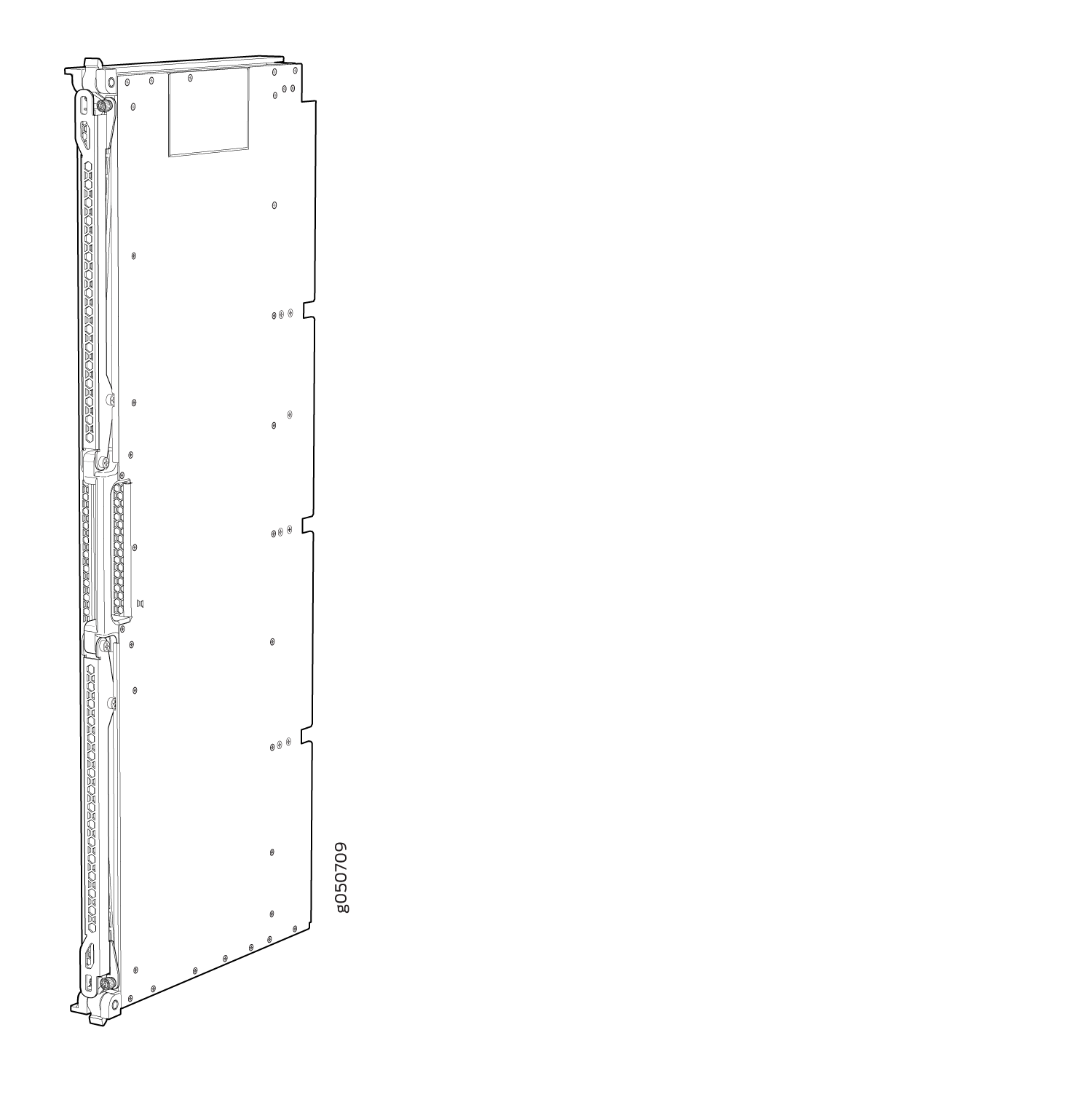
Switch Interface Boards
Five switch interface boards (SIBs) provide the necessary switching functionality to a base configuration QFX10016. A sixth SIB is available in the redundant configuration to provide n+1 redundancy. SIBs are installed between the line cards and the fan trays inside of the chassis (see Figure 7). Each QFX10016 SIB has 16 connectors that match to a line card slot, eliminating the need for a backplane. When all six SIBs are installed, the QFX10016 has a net switching capacity of 96 Tbps. See QFX10016 Switch Interface Board Description.
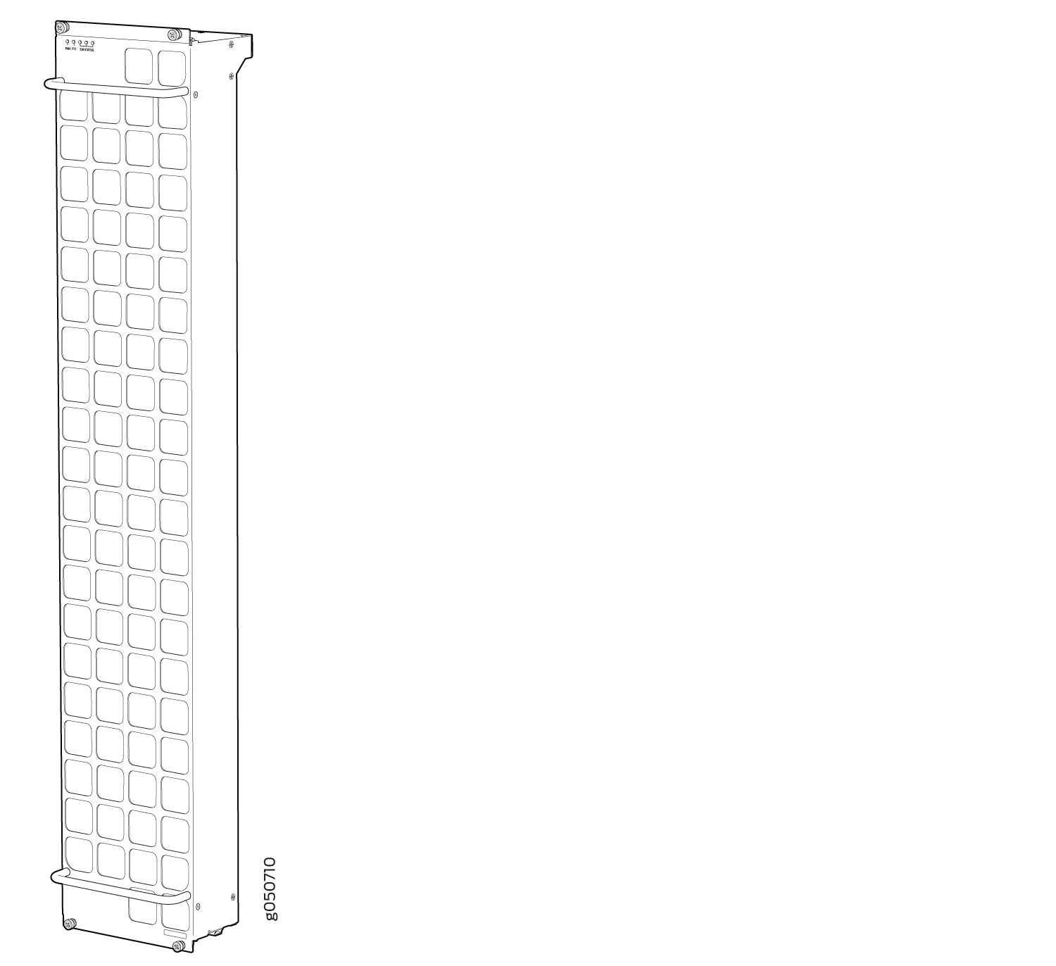
Cooling System
The cooling system in a QFX10016 consists of two hot-removable and hot-insertable FRU fan trays (see Figure 8) and two fan tray controllers (see Figure 9). Each fan tray contains 21 fans. The fan trays install vertically on the rear of the chassis and provide front-to-back chassis cooling. See QFX10016 Cooling System and Airflow.
Power Supplies
The QFX10000 switches support AC, DC, high-voltage alternating current (HVAC) and high-voltage direct current (HVDC) by offering the following power supplies:
-
QFX10000-PWR-AC
-
JNP10K-PWR-AC2
-
QFX10000-PWR-DC
-
JNP10K-PWR-DC2
All of the power supplies for the QFX10000 are fully redundant, load-sharing, and hot-removable and hot-insertable FRUs. Each QFX10016 base configuration has five power supplies; redundant configurations hold the maximum of ten AC HVAC, DC, or HVDC power supplies. Each power supply has an internal fan for cooling. You can install the power supplies in any slot. See Table 2 and Figure 10 through Figure 13.
The JNP10K-PWR-AC2 and JNP10K-PWR-DC2 PSMs work optimally with the enhanced power bus. To determine whether your system has the standard power bus or the enhanced power bus, see QFX10000 Status Panel. Table 2 provides the specifications for these different power supplies.
|
QFX10000-PWR-AC |
JNP10K-PWR-AC2 |
QFX10000-PWR-DC |
JNP10K-PWR-DC2 |
|
|---|---|---|---|---|
|
Maximum output power |
2700 W |
5000 W, single feed or 5500 W, dual feed when set for high power (30-A); 3000 W when set for low power (20-A) |
2500 W |
5500 W when set for high power (80-A) or 4400 W when set for low power (60-A) |
|
Inputs |
2 AC only(INP1, INP2) |
2 AC, HVAC, or HVDC (INP1, INP2) |
2 DC only (INPUT 1, INPUT 2) |
4 DC only (INPUT 1, INPUT 2) |
|
Compatible power bus |
Standard or enhanced |
Standard or enhanced * |
Standard or enhanced |
Standard or enhanced* |
|
Note:
*The JNP10K-PWR-AC2 and the JNP10K-PWR-DC2 power supplies are supported on both the standard and enhanced chassis. However, when these models are run in a standard chassis, the power management software sets the power budget to 3000 W. |
||||
Do not mix power supply models in the same chassis in a running environment. DC and HVDC can coexist in the same chassis during the hot swap of DC for HVDC.
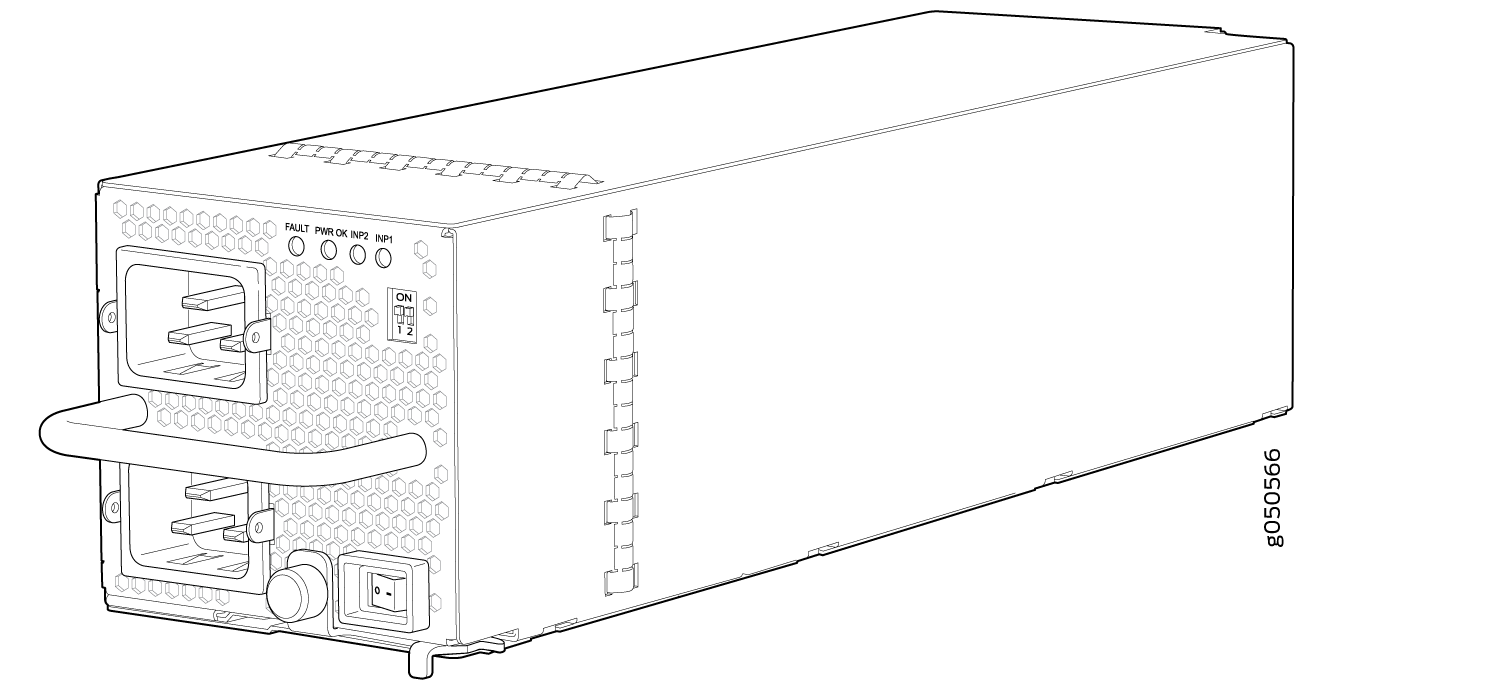
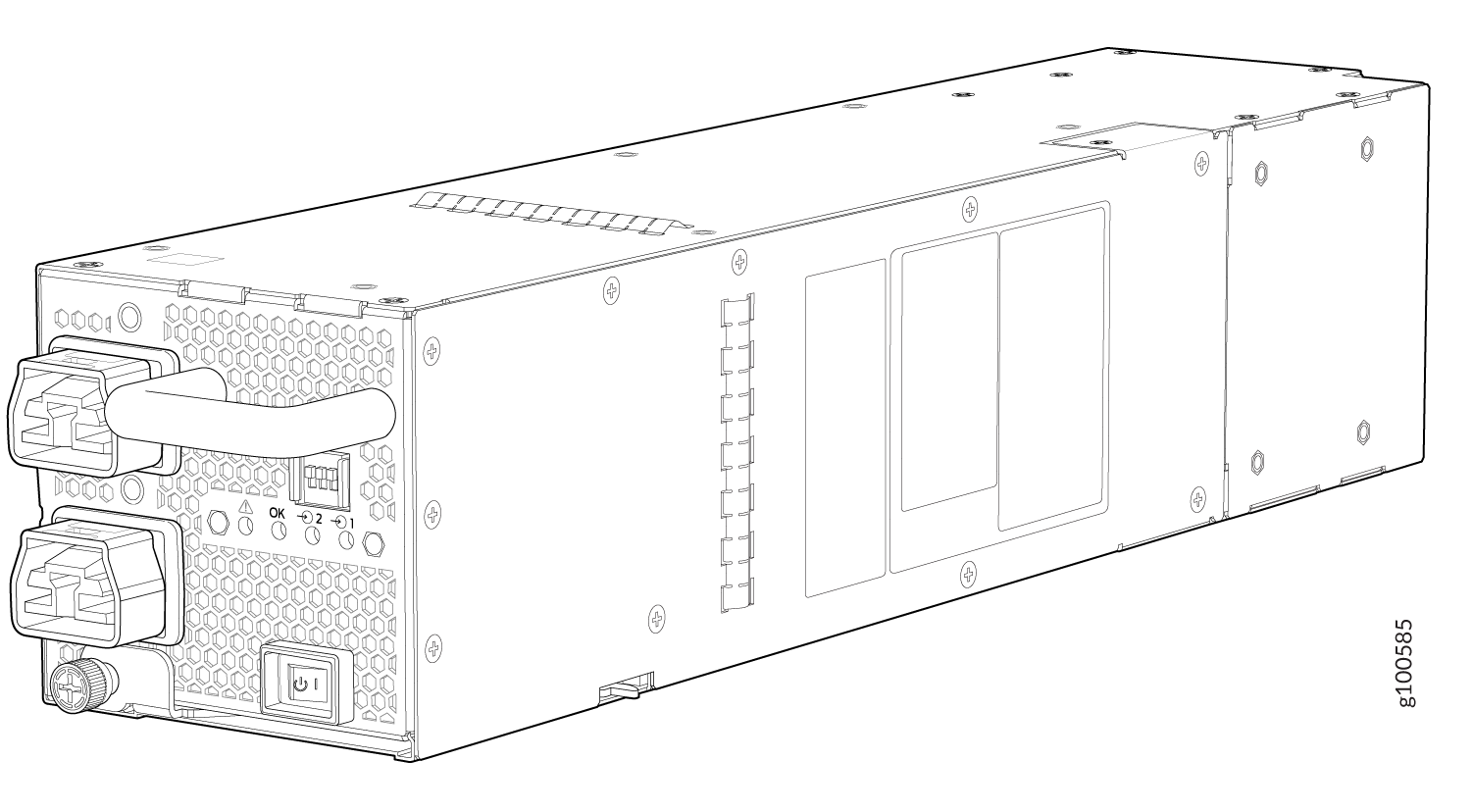
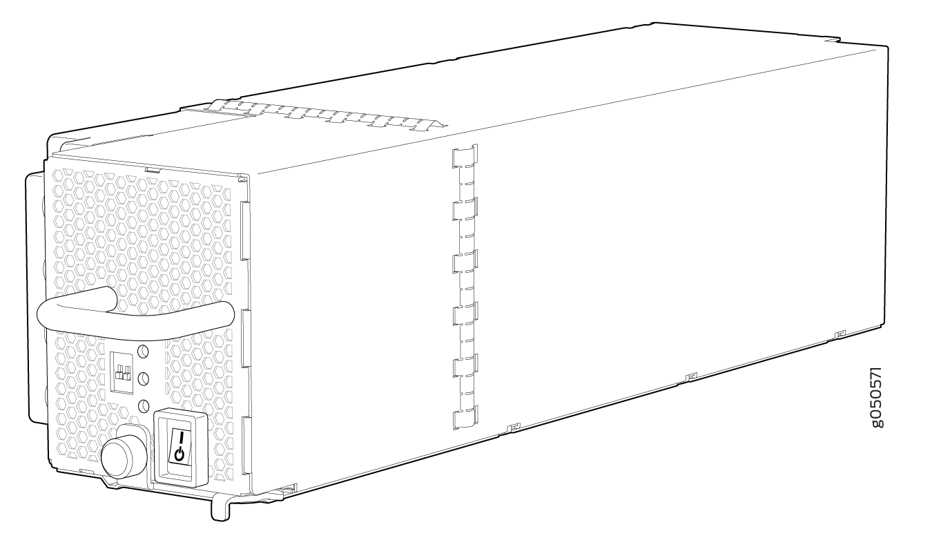
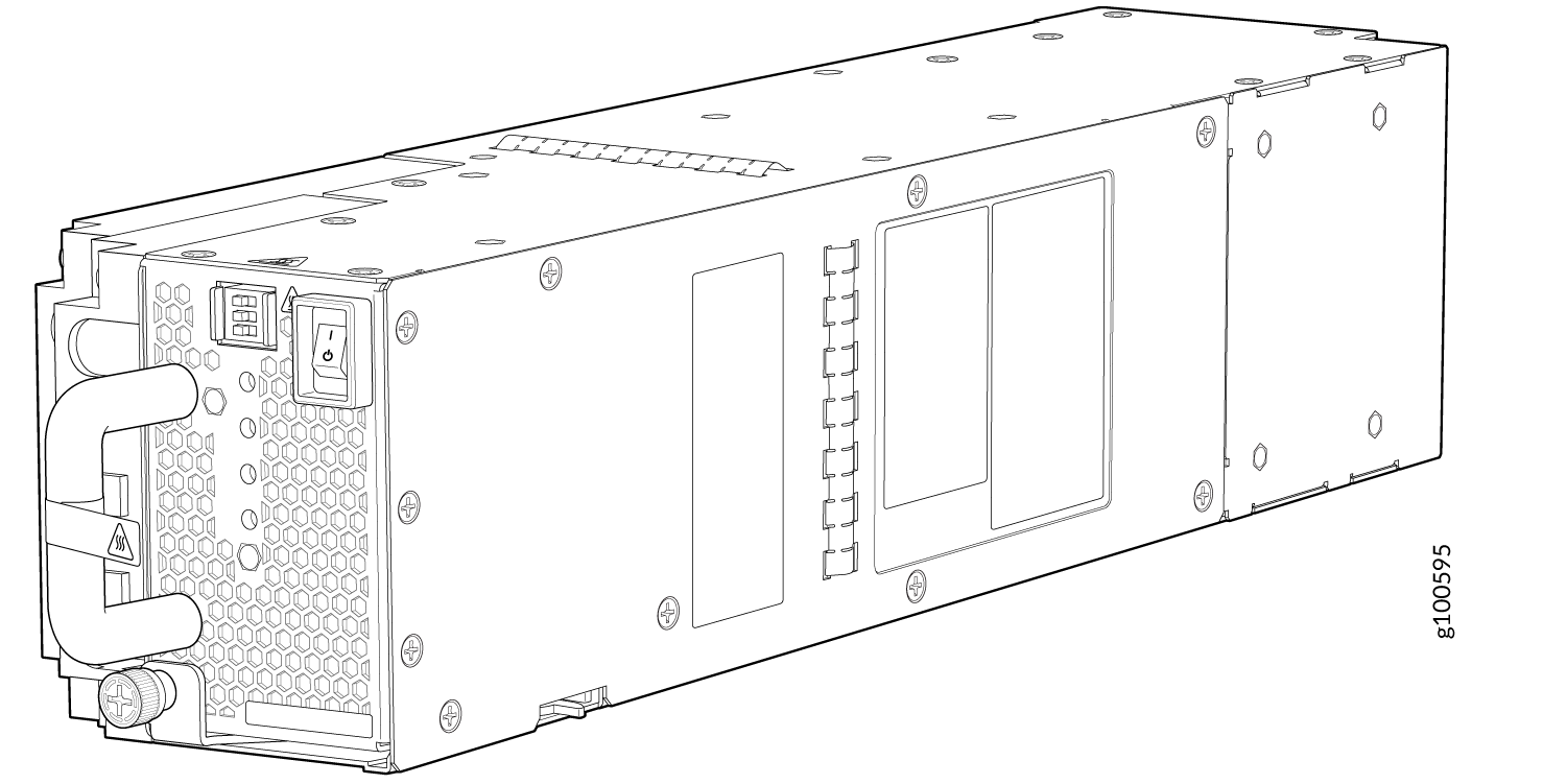
Table 2 provides an overview of the differences among the power supplies.
Software
The Juniper Networks QFX Series Ethernet Switches run Junos OS, which provides Layer 2 and Layer 3 switching, routing, and security services. The same Junos OS code base that runs on QFX Series switches also runs on all Juniper Networks EX Series, M Series, MX Series, and T Series routers and SRX Series Firewalls. The minimum Junos OS release is 15.1X53-D61.
QFX10016 Components and Configurations
Table 3 lists the four hardware configurations for a QFX10016 modular chassis—base (AC version), and redundant (AC and DC versions)—and the components included in each configuration.
Switch Configuration |
Configuration Components |
|---|---|
Base AC configuration QFX10016-BASE |
|
Redundant AC configuration QFX10016-REDUND |
|
Redundant DC configuration QFX10016-REDUND-DC |
|
You can install up to 8 line cards (any combination of line cards) in the QFX10008 and 16 line cards in the QFX10016.
Line cards, the cable management system, and the SATA solid state drive are not part of the base or redundant configurations. You must order them separately.
If you want to purchase additional power supplies (AC or DC), SIBs, or RCBs for your switch configuration, you must order them separately.
See Also
QFX10000 Hardware and CLI Terminology Mapping
This topic describes the hardware terms used in QFX10000 documentation and the corresponding terms used in the Junos OS CLI. See Table 4.
Hardware Item (CLI) |
Description (CLI) |
Value (CLI) |
Item In Documentation |
Additional Information |
|---|---|---|---|---|
Chassis |
QFX10008 QFX10016 |
– |
Switch chassis |
QFX10008 Physical Specifications and QFX10016 Chassis Physical Specifications |
Routing and Control Board |
CB (n) |
n is a value in the range of 0–1. Multiple line items appear in the CLI if more than one RCB (CB) is installed in the chassis. |
||
FPC (n) |
Abbreviated name of the Flexible PIC Concentrator (FPC) On QFX10008 and QFX10016, an FPC equates to a line card. |
n is a value in the range of 0–7 for the QFX10008 and 0–15 for the QFX10016. The value corresponds to the line card slot number in which the line card is installed. |
Line card (The switch does not have actual FPCs—the line cards are the FPC equivalents on the switch.) |
|
Xcvr (n) |
Abbreviated name of the transceiver |
n is a value equivalent to the number of the port in which the transceiver is installed. |
Optical transceivers |
|
PSU (n) |
One of the following:
|
n is a value in the range of 0–5. The value corresponds to the power supply slot number. |
AC, DC, HVAC, or HVDC |
|
Fan tray |
QFX10008-FAN JNP10008-FAN2 QFX10016-FAN |
– |
Fan tray |
|
SIB (n) |
This field indicates:
|
n is a value in the range of 0–5. |
Fabric plane |
show chassis fabric sibs |
PIC (n) |
– |
Value of n is always 0. |
– |
QFX10000 Component Redundancy
The QFX10000 is designed so that no single point of failure can cause the entire system to fail. The following major hardware components in the redundant configuration provide redundancy:
Routing and Control Board (RCB)—The RCB consolidates the Routing Engine function with control plane function in a single unit. The QFX10000 can have one or two RCBs. When two RCBs are installed, one functions as the primary and the other functions as the backup. If the primary RCB (or either of its components) fails, the backup can take over as the primary. See QFX10000 Routing and Control Board Description.
Switch Interface Boards (SIBs)—The QFX10000 has six SIB slots. Five SIBs are required for base operation and the sixth SIB provides n+1 redundancy. All six SIBs are active and can sustain full throughput rate. The fabric plane can tolerate one SIB failure without any loss of performance. See the QFX10008 Switch Interface Board Description and QFX10016 Switch Interface Board Description.
Power supplies—The QFX10000 requires three power supplies for minimum operation (two RCBs, two fan trays, six SIBs and no line cards). With additional power supplies, it provides n+1 redundancy for the system. AC, DC, HVAC, and HVDC systems tolerate a single power supply to fail without system interruption. If one power supply fails in a fully redundant system, the other power supplies can provide full power to the QFX10000 indefinitely.
The QFX10000 also supports source redundancy. Two sets of lugs are provided for the QFX10000-PWR-AC cables, four sets of lugs are provided for the JNP10K-PWR-DC2 cables, and two AC power cords are provided for each JNP10K-PWR-AC2 power supply.
Cooling system—The fan trays have redundant fans, which are controlled by the fan tray controller. If one of the fans fails, the host subsystem increases the speed of the remaining fans to provide sufficient cooling for the switch indefinitely. See QFX10008 Cooling System and Airflow and QFX10016 Cooling System and Airflow .