QFX10008 Chassis
QFX10000 Field-Replaceable Units
Field-replaceable units (FRUs) are switch components that you can replace at your site. The switch uses these types of FRUs:
Hot-insertable and hot-removable—You can remove and replace these components without powering off the switch or disrupting the switching function.
Hot-pluggable—You can remove and replace these components without powering off the switch, but the switching function is interrupted until you replace the component.
Table 1 lists the FRUs and their types for the QFX10000.
FRU |
Type |
|---|---|
Power supplies |
Hot-insertable and hot-removable. |
Fan tray |
Hot-insertable and hot-removable. |
Fan tray controller |
Hot-insertable and hot-removable. |
Routing Control Board (RCB) |
Redundant configuration:
Base configuration:
See QFX10008 Configurations and Upgrade Options and QFX10016 Components and Configurations. |
Switch Interface Boards (SIBs) |
SIBs are hot-insertable and hot-removable. We recommend that you take SIBs offline before removing them to avoid traffic loss while the switch fabric is being reconfigured. For example: user@switch> request chassis sib (offline | online) slot slot-number offline |
Line cards |
Hot-insertable and hot-removable. We recommend that you take line cards offline before removing them. For example: user@switch> request chassis fpc slot slot-number offline |
Optical transceivers See the Hardware Compatibility Tool. |
Hot-insertable and hot-removable. |
Line cards are not part of the base or redundant configuration. You must order them separately.
If you have a Juniper Care service contract, register any addition, change, or upgrade of hardware components at https://www.juniper.net/customers/support/tools/updateinstallbase/. Failure to do so can result in significant delays if you need replacement parts. This note does not apply if you replace an existing component with the same type of component.
QFX10000 Status Panel
The status panel of the QFX10008 and QFX10016 has two purposes:
Shows the overall status of the chassis
Indicates the type of power bus internal to the chassis
Some chassis ship with an enhanced power bus to support the power needs of higher wattage line cards.
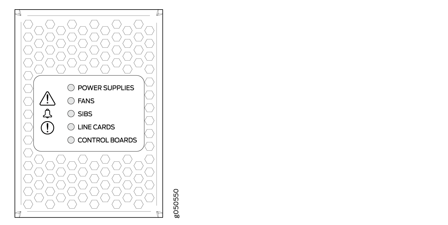
The status panel indicates chassis status through a set of five bi-color LEDs. See Figure 1 for chassis with the original power bus.
Other chassis have the same set of five bi-color LEDs, but also have an azure blue line to indicate the enhanced power bus (see Figure 2).
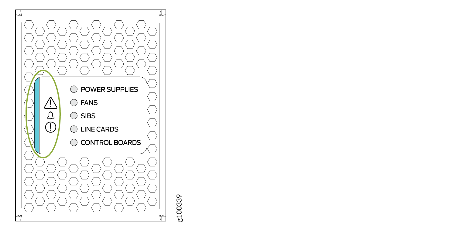
Table 2 describes the status panel LEDs.
Name |
Color |
State |
Description |
|---|---|---|---|
Power supplies |
Green |
On steadily |
All of the power supplies are online and operating normally. |
Yellow |
On steadily |
One or more of the power supplies has an error. |
|
None |
Off |
None of the power supplies is receiving power. |
|
Fans |
Green |
On steadily |
The fans and the fan tray controllers are online and operating normally. |
Yellow |
On steadily |
There is an error in a fan or in one of the fan tray controllers. |
|
None |
Off |
The fan tray controllers and fan trays are not receiving power. |
|
SIBs |
Green |
On steadily |
All installed Switch Interface Boards (SIBs) are online. |
Yellow |
On steadily |
There is an error in one or more SIBs. |
|
None |
Off |
One or more SIBs are offline. |
|
Line cards |
Green |
On steadily |
All installed line cards are online. |
Yellow |
On steadily |
One or more line cards have an error condition. |
|
None |
Off |
One or more line cards are offline. |
|
Routing Control Boards |
Green |
On steadily |
All installed RCBs are online. |
Yellow |
Blinking |
One or more RCBs have an error condition. |
|
None |
Off |
The installed RCBs are offline. |
See Also
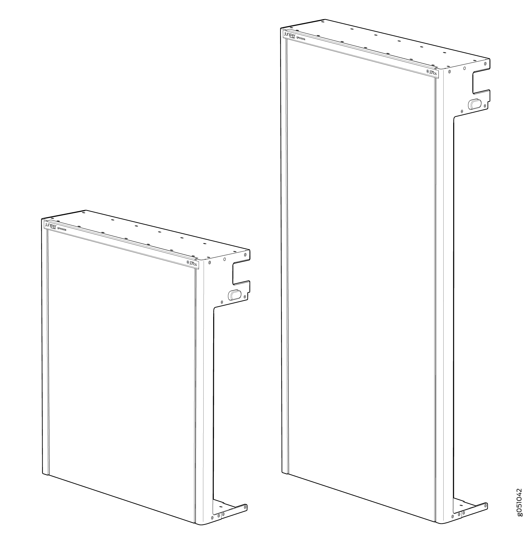
QFX10000 EMI Front Panel
The QFX10000 modular chassis models come equipped with a screened door, or panel, that provides additional electromagnetic interference (EMI) protection.
The panel attaches to the front of the chassis and swings open to allow easy access to optics and line cards, see Figure 3 and Table 3.
Model |
Dimensions |
Weight |
|---|---|---|
QFX10008 |
22.25 in. H x 17.70 in. W x 6.10 in. D |
12.8 lb |
QFX10016 |
36.43 in. H x 17.70 in. W x 6.10 in. D |
20.3 lb |
See Also
QFX10000 Optional Equipment
The QFX10000 line of modular chassis switches supports the following optional equipment and systems:
QFX10000 Cable Management System
The QFX10000 cable management system (see Figure 4) enables you to route optical cables away from the line card ports for better airflow through the chassis. Using this optional system also makes it easier to use cable ties or strips to organize the cabling.
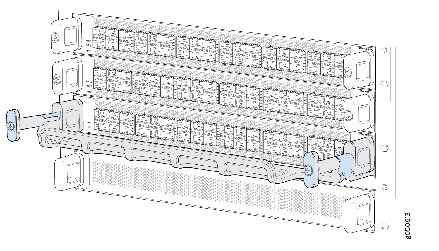
The cable management system is comprised of a set of handle extensions and a tray that snaps to the extensions (see Figure 5) for an individual line card. The handle extensions can be used with or without the cable tray. It is not necessary to remove the handle extensions if you want to remove a line card.
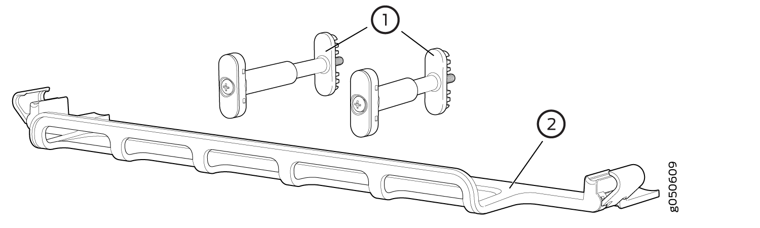
1 — Handle extensions | 2 — Cable tray |
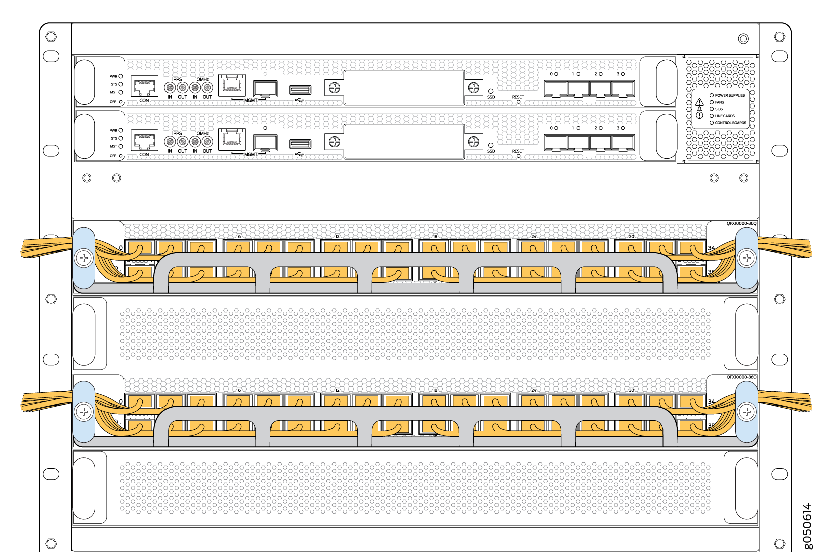
Cables are draped across or under the handle extensions and then secured with cable wraps (see Figure 6).
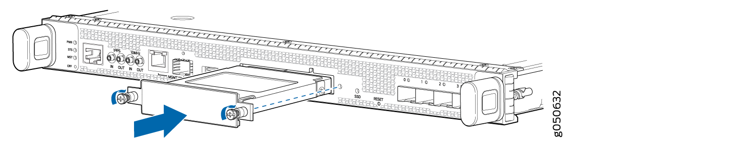
QFX10000 SATA SSD
The QFX10000 line of modular chassis switches allows you to install one of two Serial Advanced Technology Attachment (SATA) solid-state drives (SSDs) as a secondary boot drive or for log storage. The drive is available in either a 50 GB or 100 GB version. The SATA SSD is field-replaceable unit (FRU) that is installed in the front panel of a Routing and Control Board (see Figure 7).