Maintaining QFX10000 Solid State Drives
Removing the Optional SATA Solid State Drive in a QFX10000
The QFX100000 allows optional installation of either a 50 GB or a 100 GB serial advanced technology attachment (SATA) solid state drive (SSD) as a secondary boot drive or for log storage. The SATA SSD is a field-replaceable unit (FRU).
Before you remove an SATA SSD from the switch:
Drain traffic queues to prevent traffic loss.
Ensure that you understand how to prevent ESD damage. See Prevention of Electrostatic Discharge Damage.
Ensure that you have the following parts and tools available to remove an SATA SSD from a QFX10000:
Electrostatic discharge (ESD) grounding strap
Phillips (+) screwdriver, number 1
An electrostatic bag or antistatic mat
To remove either size of SATA SSD in a QFX10000:
- Attach the ESD grounding strap to your bare wrist, and
connect the strap to the ESD point on the chassis. There is an ESD
point located above the status LED panel on the right side of the
switch chassis (see Figure 1 and Figure 2).Figure 1: ESD Point on QFX10008 Chassis Front
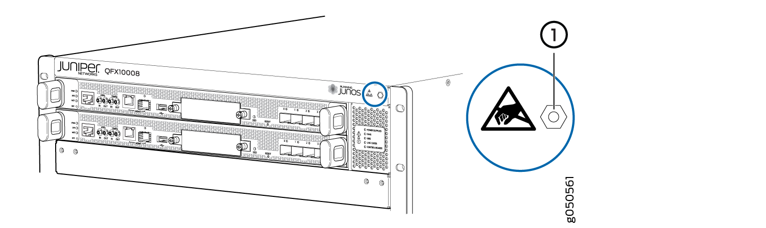 Figure 2: ESD Point on QFX10016 Chassis Front
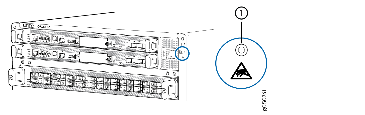 1—
1—ESD point
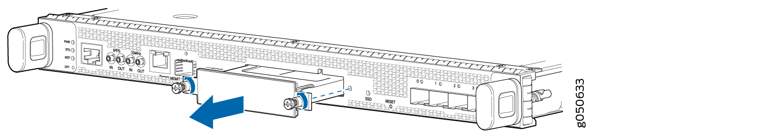
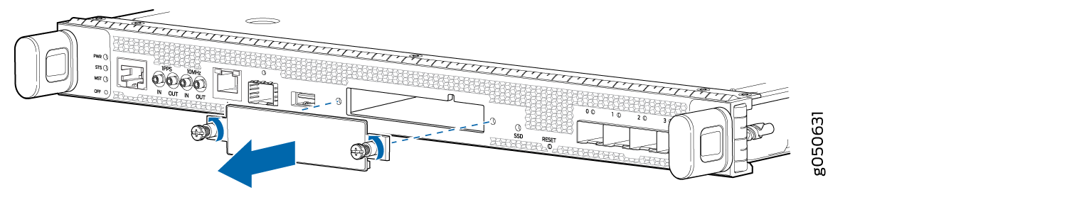
- Grasp the faceplate of the SATA SSD by the captive screws
and slide the drive out of the control panel (see Figure 3).Figure 3: Removing the SATA SSD
Installing the Optional SATA Solid State Drive in a QFX10000
The QFX100000 allows optional installation of either a 50 GB or a 100 GB serial advanced technology attachment (SATA) solid state drive (SSD) as a secondary boot drive or for log storage. The SATA SSD is a field-replaceable unit (FRU).
Before you install an SATA SSD in the switch, ensure you that understand how to prevent ESD damage. See Prevention of Electrostatic Discharge Damage.
Ensure that you have the following parts and tools available to install an SATA SSD in a QFX10000:
Electrostatic discharge (ESD) grounding strap
Phillips (+) screwdriver, number 1
To install either size of SATA SSD in a QFX10000:
- Attach the ESD grounding strap to your bare wrist, and
connect the strap to the ESD point on the front of the chassis. There
is an ESD point located above the status LED panel on the right side
(see Figure 4 and Figure 5).Figure 4: ESD Point on QFX10008 Chassis FrontFigure 5: ESD Point on QFX10016 Chassis Front1—
ESD point
- Loosen the two captive screws to remove the cover on the
RCB by using the Phillips (+) screwdriver, number 1
(see Figure 6).Figure 6: Removing the SATA SSD Cover
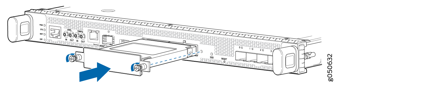
- Slide the SATA SSD into the open slot until the pins engage
and the faceplate is flush with the front panel of the Control Board
(see Figure 7).Figure 7: Installing the SATA SSD into the Slot