Maintaining QFX10000 Line Cards
Removing a QFX10000 Line Card
QFX10000 line cards are field-replaceable units (FRUs) that can be installed in the line card slots on the front of the chassis. The line cards are hot-insertable and hot-removable: you can remove and replace them without powering off the switch or disrupting switch functions. However, we recommend that you take them offline before removing them.
If you have the optional line-card cable management system, it is not necessary to remove the cable management system before removing the line card.
Before you remove a line card from the switch chassis:
Ensure that you have taken the necessary precautions to prevent electrostatic discharge (ESD) damage. See Prevention of Electrostatic Discharge Damage.
If there are any optical cables, (including transceivers, direct-attach copper (DAC), or DAC break-out) installed in the line card), remove them before you remove the line card. See Removing a Transceiver.
Ensure that you know how to handle and store the line card. See Unpacking QFX10000 Line Cards, Routing and Control Boards, and Switch Interface Boards.
Ensure that you have the following parts and tools available to remove a line card from a QFX10000 chassis:
ESD grounding strap
An electrostatic bag or an antistatic mat
Note:Placing a line card in an electrostatic bag might require a second person to assist with sliding the line card into the bag.
Replacement line card or a cover for the empty slot
To remove a line card from a QFX10000 switch chassis:
- Attach the ESD grounding strap to your bare wrist and
connect the strap to the ESD point above the status LEDs on the switch
chassis (see Figure 1). Figure 1: ESD Point on QFX10008 Chassis Front
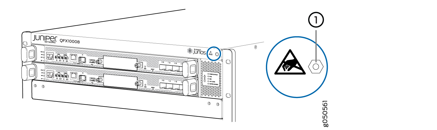 1—
1—ESD point
Figure 2: ESD Point on QFX10016 Chassis Front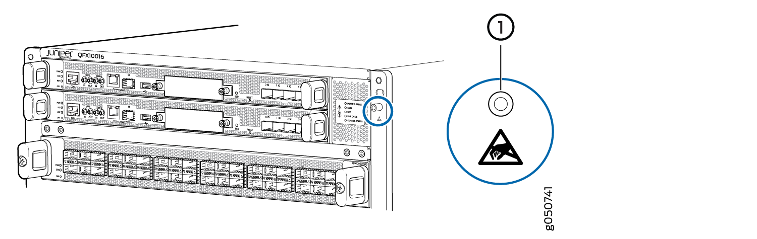 1—
1—ESD point
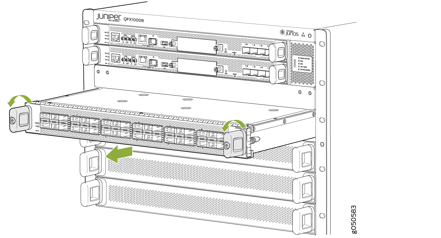
- Unscrew the line card from the chassis by continually
turning the handles to the left until the line card is fully unseated.
See Figure 3.Figure 3: Removing a QFX10000 Line Card
- Grasp both sides of line card at midpoint and remove the
line card from the chassis. Either have someone assist you in putting
the line card into the electrostatic bag or rest the card on the antistatic
mat. Take care not to bump or store the line cards on the connectors.
See Figure 4.Figure 4: QFX10000 Line Card Connectors
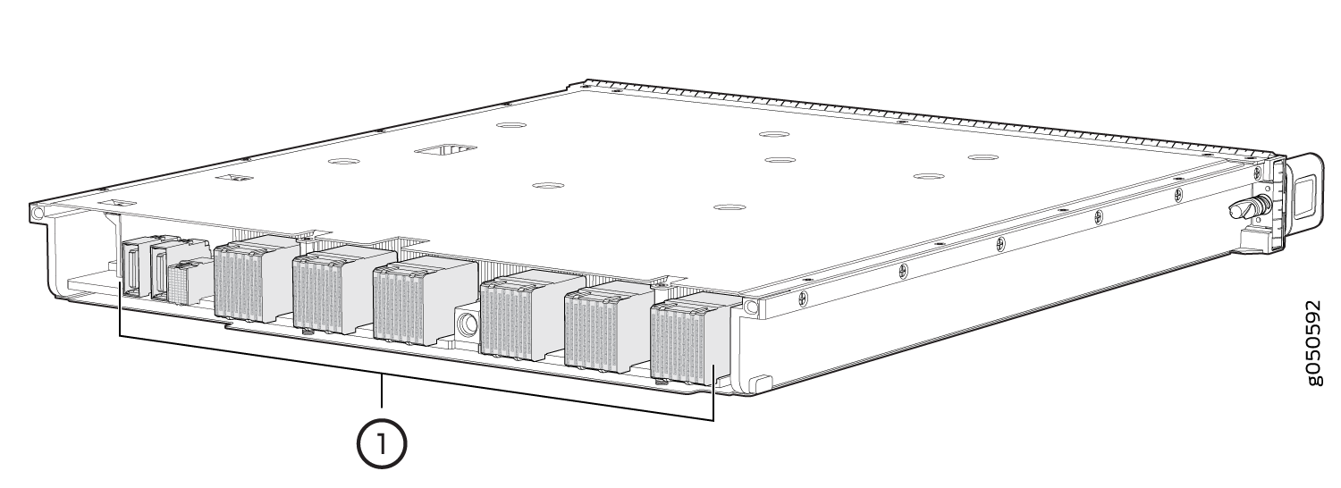 1—
1—Connectors
See Also
Installing a QFX10000 Line Card
QFX10000 line cards are field-replaceable units (FRUs) that can be installed in any of the line card slots on the front of the chassis. The line cards are hot-insertable and hot-removable: you can remove and replace them without powering off the switch or disrupting switch functions.
Before you install a line card in the switch chassis:
Ensure that you have taken the necessary precautions to prevent electrostatic discharge (ESD) damage. See Prevention of Electrostatic Discharge Damage.
Ensure that you know how to handle and store the line card. See Handling and Storing QFX10000 Line Cards, RCBs, and SIBs.
Inspect the connector edge of the line card for physical damage. Installing a damaged line card might damage the switch.
Ensure that the switch has sufficient power to power the line card while maintaining its N+1 power redundancy. To determine whether the switch has enough power available for the line card, use the
show chassis power-budget-statisticscommand. See also Power Requirements for QFX10000 Components.Ensure that you have the following parts and tools available to install a line card in the switch:
ESD grounding strap
Phillips (+) screwdriver, number 2
To install a line card in the switch chassis:
- Attach the ESD grounding strap to your bare wrist and
connect the strap to the ESD point on the switch chassis. The ESD
point is located above the status LED panel on the front of the switch
chassis. See Figure 5 and Figure 6.Figure 5: ESD Point on QFX10008 Chassis Front1—
ESD point
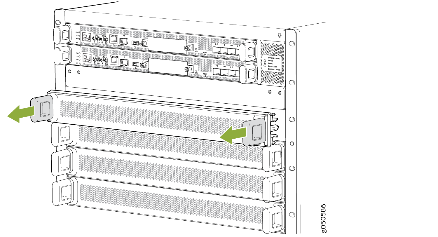
Figure 6: ESD Point on QFX10016 Chassis Front - Remove the cover panel by grasping the handles and pulling
straight out to expose the slot for the line card. See Figure 7.Figure 7: Removing the Cover for a Line Card
 CAUTION:
Do not lift the line card by holding the edge connectors or the handles on the faceplate. Neither the handles or the edge connectors can support the weight of the line card. Lifting the line card by the handles or edge connectors might bend them, which would prevent the line cards from being properly seated in the chassis. See Figure 8.
Figure 8: Line Card Connectors1—Connectors
- Slide the line card all the way into the slot until the
handle holes align. See Figure 9.Figure 9: Inserting a Line Card into the Slot and Rotating the Handles
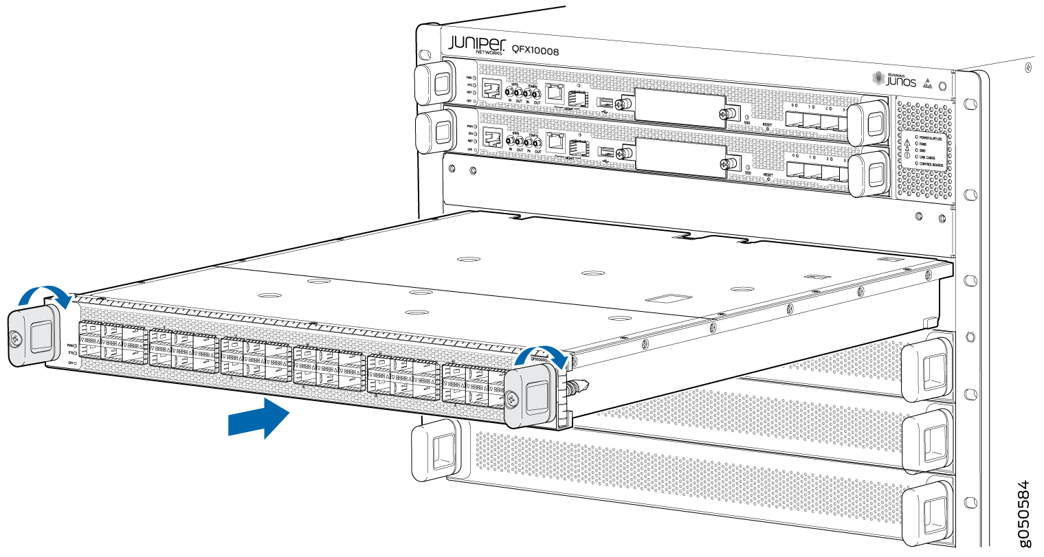
You can install the optional cable management kit after the card is installed.
See Also
Installing the QFX10000 Cable Management System
The QFX10000 cable management system is an optional kit that can be ordered to organize and protect optical cabling attached to the line cards. After a card is installed, you can still remove the line card without needing to remove the cable management system.
Ensure that you have the following parts and tools available to install the QFX10000 cable management system on a line card:
Phillips (+) screwdriver, number 2
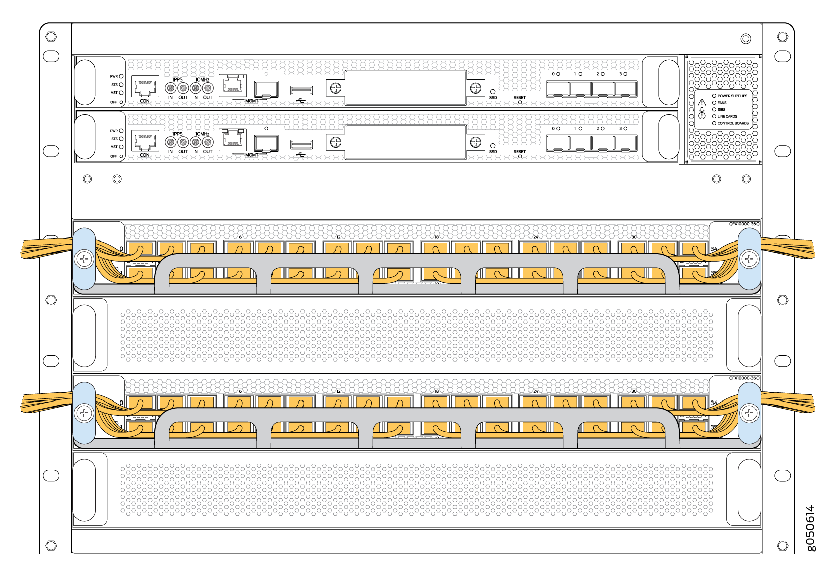
To install the cable management system (see Figure 10):
- Open the shipping carton for cable management system and
check that you have:
Two handle extensions
One cable tray
Figure 10: Cable Management System Components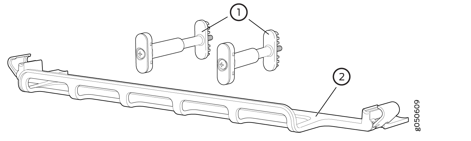
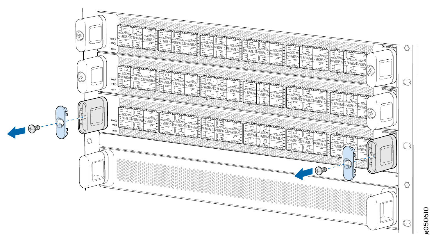
- Use the Phillips screwdriver to loosen and remove the
screws on the two line card handles (see Figure 11).Figure 11: Removing the Handle Screws
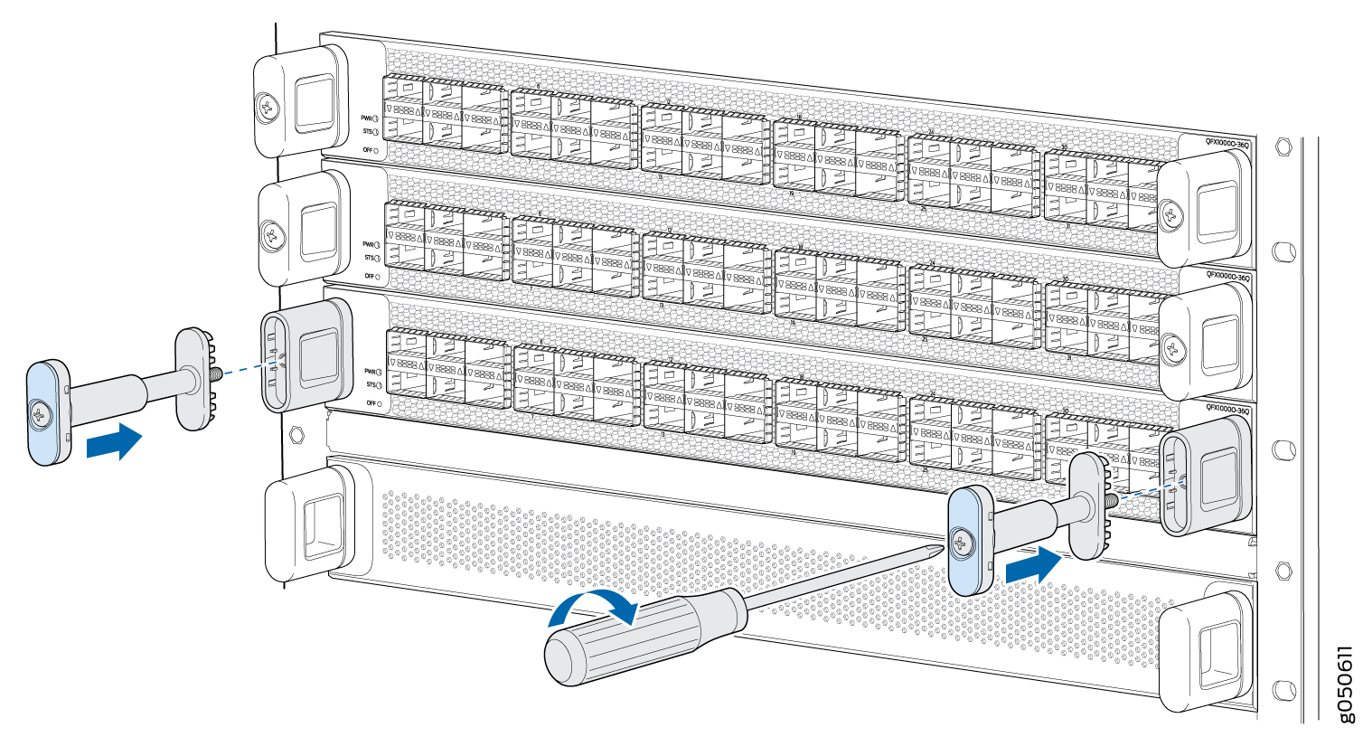
- Replace the blue cap on the line card handle with the
two handle extensions (see Figure 12).Figure 12: Adding Handle Extensions
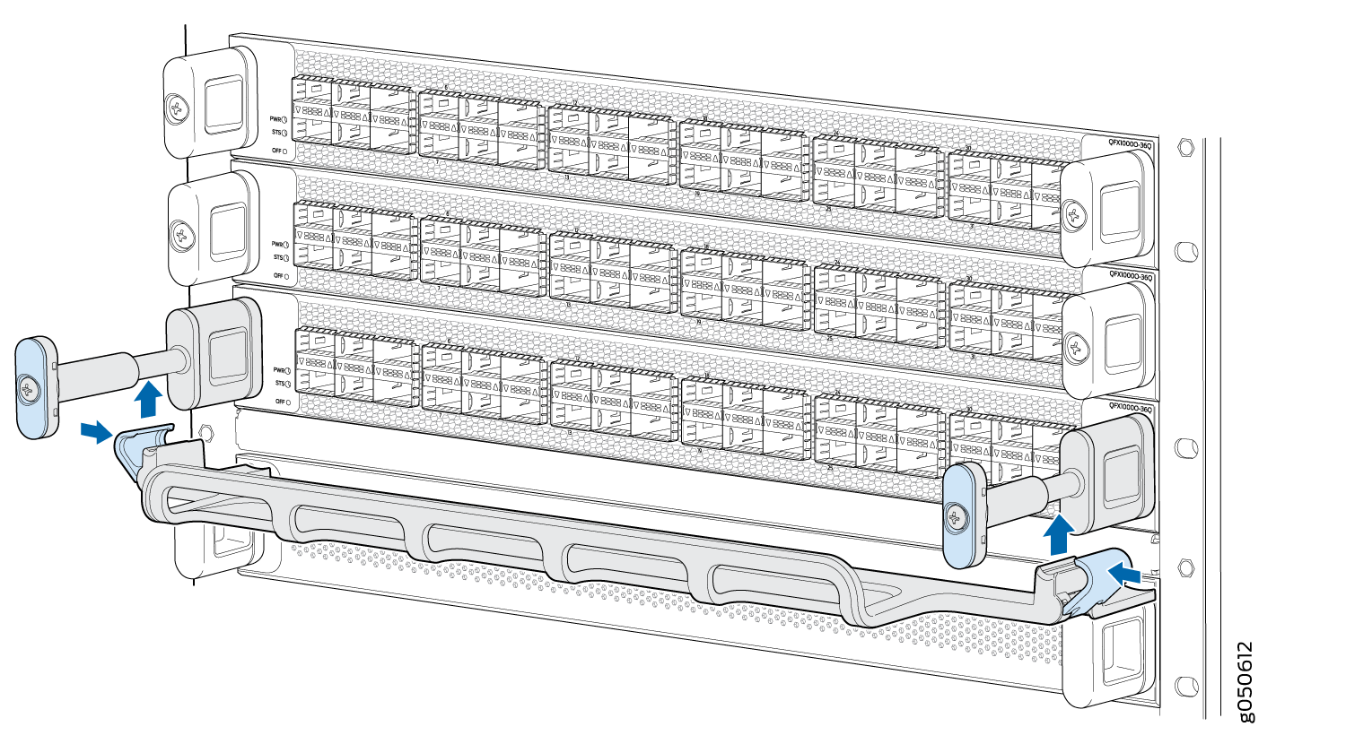
- Snap to close the blue clips of the cable tray around
the handle extensions (see Figure 13).Figure 13: Adding the Cable Tray
- Drape and tie the optical cables to the side (see Figure 14). Another option is to drape
some of the cables under the handle extension and some cables over
the handle extension.Figure 14: Completed Cable Management System