QFX10016 Cooling System
The QFX10016 cooling system components work together to keep all components within the acceptable temperature range. If the maximum temperature specification is exceeded and the system cannot be adequately cooled, the Routing and Control Board shuts down some or all of the hardware components.
QFX10016 Cooling System and Airflow
The cooling system in a QFX10016 chassis consists of dual fan trays and dual fan tray controllers. There is no air filter in a QFX10016.
Fan Tray QFX10016-FAN
Each fan tray is a hot-insertable and hot-removable FRU. Each fan tray contains 21 fans (0-20), a non-removable Control Board, and LEDs.
The two fan trays install vertically, side by side, next to the power supplies on the FRU side of the chassis. Two handles on each front faceplate facilitate handling of the fan tray. See Figure 1.
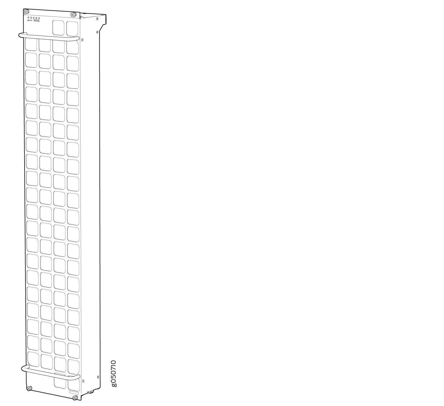
See Table 1 for the physical specifications for the fan trays.
Specification |
Value |
|---|---|
Height |
36.6 in. (92.97 cm) |
Width |
6.6 in. (16.8 cm) |
Depth |
4.0 in. (10.2 cm) without handles, 5.3 in. (13.46 cm) with handles |
Weight |
19.8 lb. (8.98 kg) |
Only remove one fan tray when replacing an existing fan tray while the switch is running. The switch continues to operate for a limited time with a single operating fan tray without triggering a thermal alarm.
To avoid a thermal alarm, do not remove both fan trays while the switch is operating.
The chassis will shut down if a thermal alarm is raised for more than three minutes.
The internal fan Control Board in each fan tray contains the LEDs for the associated fan tray controllers and the LEDs for the three SIBs directly behind the fan tray.
Fan Tray Controller
The two fan tray controllers provide the control logic and power to hot-insert and hot-remove a fan tray. The fans in each fan tray are numbered 0 through 20.
The system continually monitors the temperature of critical parts across the chassis and adjusts the chassis fan speed according to the temperature.
Software controls the fan speed. Under
normal operating conditions, the fans in the fan tray run at less
than full speed. If one fan tray controller fails
or appears missing (such as when a SIB is being replaced) the other
fan tray controller sets the fans to full speed. This allows the switch
to continue to operate normally as long as the remaining fans cool
the chassis sufficiently. Use the show chassis fan command
to see the status of individual fans and fan speed. For example:
user@device> show chassis fan
      Item                      Status   RPM     Measurement
      Fan Tray 0 Fan 0          OK       4500    Spinning at normal speed
      Fan Tray 0 Fan 1          OK       4650    Spinning at normal speed
      Fan Tray 0 Fan 2          OK       4650    Spinning at normal speed
      Fan Tray 0 Fan 3          OK       4800    Spinning at normal speed
      Fan Tray 0 Fan 4          OK       4650    Spinning at normal speed
      Fan Tray 0 Fan 5          OK       4650    Spinning at normal speed
      Fan Tray 0 Fan 6          OK       4650    Spinning at normal speed
      Fan Tray 0 Fan 7          OK       4500    Spinning at normal speed
      Fan Tray 0 Fan 8          OK       4500    Spinning at normal speed
      Fan Tray 0 Fan 9          OK       4650    Spinning at normal speed
      Fan Tray 0 Fan 10         OK       4650    Spinning at normal speed
      Fan Tray 0 Fan 11         OK       4500    Spinning at normal speed
      Fan Tray 0 Fan 12         OK       4500    Spinning at normal speed
      Fan Tray 0 Fan 13         OK       4500    Spinning at normal speed
      Fan Tray 0 Fan 14         OK       4650    Spinning at normal speed
      Fan Tray 0 Fan 15         OK       4350    Spinning at normal speed
      Fan Tray 0 Fan 16         OK       4500    Spinning at normal speed
      Fan Tray 0 Fan 17         OK       4500    Spinning at normal speed
      Fan Tray 0 Fan 18         OK       4350    Spinning at normal speed
      Fan Tray 0 Fan 19         OK       4500    Spinning at normal speed
      Fan Tray 0 Fan 20         OK       4500    Spinning at normal speed
      Fan Tray 1 Fan 0          OK       4500    Spinning at normal speed
      Fan Tray 1 Fan 1          OK       4650    Spinning at normal speed
      Fan Tray 1 Fan 2          OK       4500    Spinning at normal speed
      Fan Tray 1 Fan 3          OK       4500    Spinning at normal speed
      Fan Tray 1 Fan 4          OK       4650    Spinning at normal speed
      Fan Tray 1 Fan 5          OK       4650    Spinning at normal speed
      Fan Tray 1 Fan 6          OK       4650    Spinning at normal speed
      Fan Tray 1 Fan 7          OK       4500    Spinning at normal speed
      Fan Tray 1 Fan 8          OK       4500    Spinning at normal speed
      Fan Tray 1 Fan 9          OK       4650    Spinning at normal speed
      Fan Tray 1 Fan 10         OK       4500    Spinning at normal speed
      Fan Tray 1 Fan 11         OK       4500    Spinning at normal speed
      Fan Tray 1 Fan 12         OK       4500    Spinning at normal speed
      Fan Tray 1 Fan 13         OK       4650    Spinning at normal speed
      Fan Tray 1 Fan 14         OK       4500    Spinning at normal speed
      Fan Tray 1 Fan 15         OK       4650    Spinning at normal speed
      Fan Tray 1 Fan 16         OK       4650    Spinning at normal speed
      Fan Tray 1 Fan 17         OK       4650    Spinning at normal speed
      Fan Tray 1 Fan 18         OK       4650    Spinning at normal speed
      Fan Tray 1 Fan 19         OK       4500    Spinning at normal speed
      Fan Tray 1 Fan 20         OK       4500    Spinning at normal speed

user@device>
See Table 2 for the physical specifications for the fan tray controllers.
Specification |
Value |
|---|---|
Height |
1.5 in. (3.81 cm) |
Width |
6.5 in. (15.24 cm) |
Depth |
12.4 in. (31.5 cm) |
Weight |
1.5 lb. (0.68 kg) |
Airflow Direction in the QFX10016
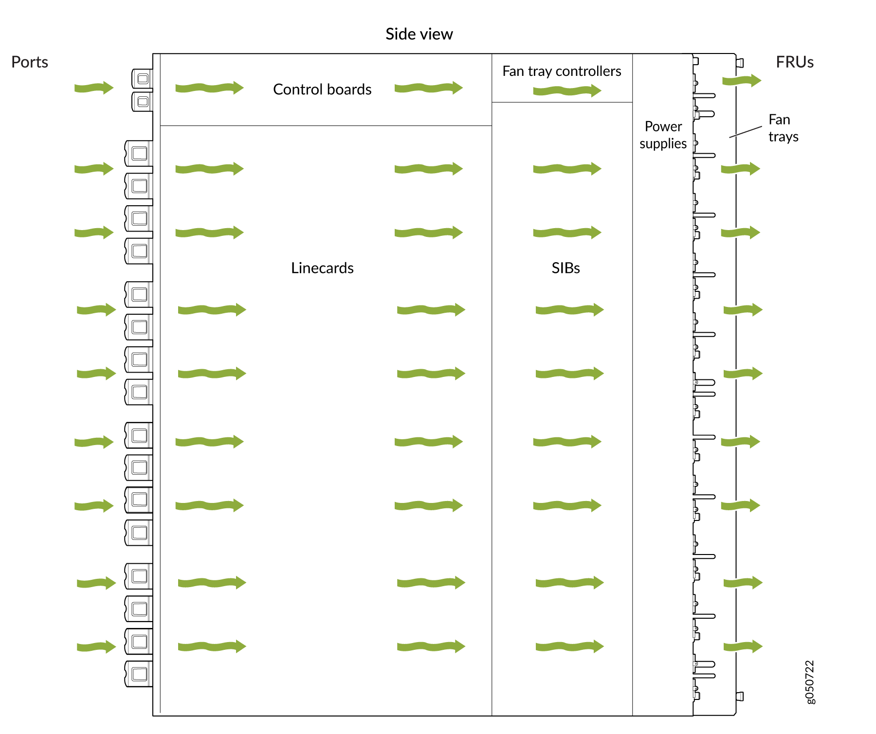
The air intake to cool the chassis is located on the port (line card) side of the chassis. Air flows into the chassis from the ports in the Routing and Control Boards (RCBs) and line cards, through the Switch Interface Boards (SIBs), and exits from the fan trays and the power supplies. This airflow is called port-to-FRU cooling or airflow out (AFO). See Figure 2.
The fan tray continues to operate indefinitely and provides sufficient cooling even when a single fan fails, provided the room temperature is within the operating range. You can check the status of fans by viewing the LEDs on each fan tray.
You cannot replace a single fan. If one or more fans fail, you must replace the entire fan tray.
In addition to the fan trays, there is an internal fan in each power supply.
See Also
QFX10000 Fan Tray LEDs and Fan Tray Controller LEDs
Each fan tray has a set of LEDs, and each corresponding fan tray controller also has a set of LEDs.
Fan Tray LEDs
The two fan trays have a set of LEDs that represent the status of the fans in the fan tray, the fan tray controller, and the three Switch Interface Boards (SIBs). The fan tray LEDs are located in the top left corner of each fan tray. Figure 3 shows the location of the LEDs on the QFX10008–FAN and QFX10016-FAN fan tray.
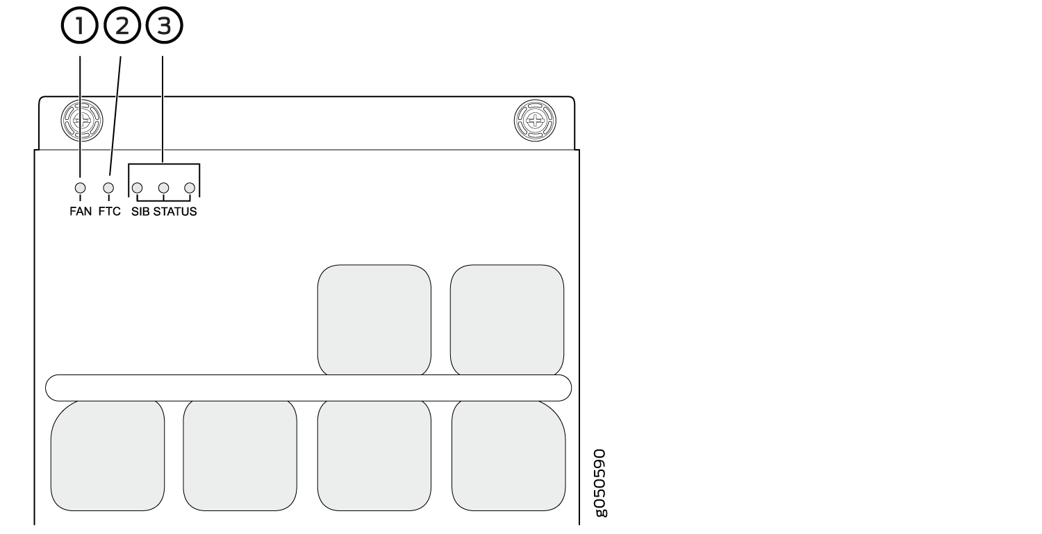
1 — Fan status LED | 3 — SIB status (SIB 0 through SIB 2 for the left fan tray and SIB 3 through 5 for the right fan tray) |
2 — Fan tray controller status |
Table 3 describes the functions of the fan tray LEDs.
Name |
Color |
State |
Description |
|---|---|---|---|
Fan status |
Green |
On steadily |
All fans are operating normally. The system has verified that the fan tray is engaged, that the airflow is in the correct direction, and that all fans are operating correctly. |
Green |
Blinking |
The beacon feature is enabled. This feature is enabled using
the |
|
Yellow |
Blinking |
An error has been detected in one or more fans in the fan tray. Replace the fan tray as soon as possible. Either the fan has failed or it has become disconnected. To maintain proper airflow through the chassis, leave the fan tray installed in the chassis until you are ready to replace it. |
|
None |
Off |
The fan is not receiving power from the fan tray controller. |
|
Fan tray controller status |
Green |
On steadily |
The fan tray controller is online and is operating normally. |
Green |
Blinking |
The beacon feature is enabled. This feature is enabled using
the |
|
Yellow |
Blinking |
An error has been detected in the fan tray controller. Replace the fan tray controller as soon as possible. The fan tray controller is located behind the fan tray above the SIBs. To maintain proper airflow through the chassis, leave the fan tray installed in the chassis until you are ready to replace the fan tray controller. |
|
None |
Off |
The fan tray controller is not receiving power. |
|
SIB 0 status |
Green |
On steadily |
The left-most SIB in the chassis is online. |
Green |
Blinking |
The beacon feature is enabled. This feature is enabled using
the |
|
Yellow |
Blinking |
An error has been detected in SIB 0. Replace the SIB as soon as possible. The SIB is located behind the left fan tray and is the left-most SIB in the chassis. To maintain proper airflow through the chassis, leave the fan tray installed in the chassis until you are ready to replace the SIB. |
|
None |
Off |
The SIB is offline. |
|
SIB 1 status |
Green |
On steadily |
The center SIB behind the left fan tray is online. |
Green |
Blinking |
The beacon feature is enabled. This feature is enabled using
the |
|
Yellow |
Blinking |
An error has been detected in SIB 1. Replace the SIB as soon as possible. The SIB is located behind the left fan tray and is the middle SIB in the grouping of 3. To maintain proper airflow through the chassis, leave the fan tray installed in the chassis until you are ready to replace the SIB. |
|
None |
Off |
The SIB is offline. |
|
SIB 2 status |
Green |
On steadily |
The right-most SIB behind the left fan tray is online. |
Green |
Blinking |
The beacon feature is enabled. This feature is enabled using
the |
|
Yellow |
Blinking |
An error has been detected in SIB 2. Replace the SIB as soon as possible. The SIB is located behind the left fan tray and is the right-most SIB in the grouping of 3. To maintain proper airflow through the chassis, leave the fan tray installed in the chassis until you are ready to replace the SIB. |
|
None |
Off |
The SIB is offline. |
|
SIB 3 status |
Green |
On steadily |
The left-most SIB behind the right fan tray is online. |
Green |
Blinking |
The beacon feature is enabled. This feature is enabled using
the |
|
Yellow |
Blinking |
An error has been detected in SIB 3. Replace the SIB as soon as possible. The SIB is located behind the right fan tray and is the left-most SIB in the grouping of 3. To maintain proper airflow through the chassis, leave the fan tray installed in the chassis until you are ready to replace the SIB. |
|
None |
Off |
The SIB is offline. |
|
SIB 4 status |
Green |
On steadily |
The center SIB behind the right fan tray is online. |
Green |
Blinking |
The beacon feature is enabled. This feature is enabled using
the |
|
Yellow |
Blinking |
An error has been detected in SIB 4. Replace the SIB as soon as possible. The SIB is located behind the right fan tray and is the middle SIB in the grouping of 3. To maintain proper airflow through the chassis, leave the fan tray installed in the chassis until you are ready to replace the SIB. |
|
None |
Off |
The SIB is offline. |
|
SIB 5 status |
Green |
On steadily |
The right-most SIB behind the right fan tray is online. |
Green |
Blinking |
The beacon feature is enabled. This feature is enabled using
the |
|
Yellow |
Blinking |
An error has been detected in SIB 5. Replace the SIB as soon as possible. The SIB is located behind the right fan tray and is the right-most SIB in the grouping of 3. To maintain proper airflow through the chassis, leave the fan tray installed in the chassis until you are ready to replace the SIB. |
|
None |
Off |
The SIB is offline. |
Fan Tray Controller LEDs
The fan tray controller LEDs are only visible when the associated fan tray is removed. The fan tray controller LEDs are located on the right of the controller panel. Figure 4 shows the location of the LEDs on the QFX10000-FAN-CTRL fan tray controller panel.

1 — Fan tray controller power | 2 — Fan tray controller status |
Table 4 describes the functions of the fan tray controller LEDs.
Name |
Color |
State |
Description |
|---|---|---|---|
Fan controller power |
Green |
On steadily |
The fan tray controller has power and is operating normally. |
Yellow |
Blinking |
A power error has been detected in the fan tray controller. Replace the fan tray controller as soon as possible. To maintain proper airflow through the chassis, leave the fan tray installed in the chassis until you are ready to replace the fan tray controller. |
|
None |
Off |
The fan tray controller is not powered on or is not receiving power. |
|
Fan tray controller status |
Green |
On steadily |
The fan tray controller is online and is operating normally. |
Green |
Blinking |
The beacon feature is enabled. This feature is enabled using
the |
|
Yellow |
Blinking |
An error has been detected in the fan tray controller. Replace the fan tray controller as soon as possible. To maintain proper airflow through the chassis, leave the fan tray installed in the chassis until you are ready to replace the fan tray controller. |
|
None |
Off |
The fan tray controller is not receiving power. |