QFX10000 AC Power System
QFX10000-PWR-AC Power Supply
QFX10000-PWR-AC Power Supply Description
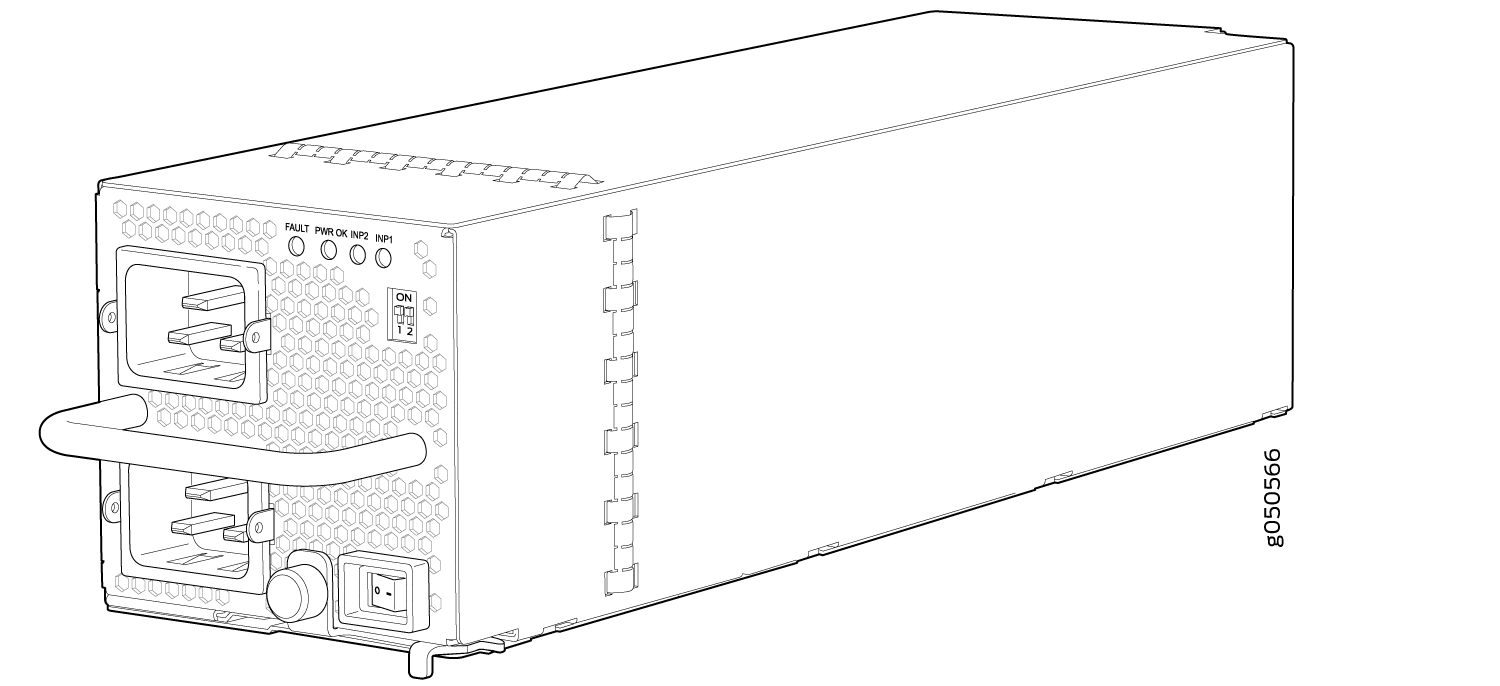
The QFX10000-PWR-AC power supply is a 2700 W, hot-insertable, hot-removable, field-replaceable unit (FRU). You can install up to six power supplies in a QFX10008 in the slots labeled PSU 0 through PSU 5 (top to bottom) located in the rear of the chassis. In QFX10016, you can install up to 10 power supplies in the slots labeled PSU 0 through PSU 9. Power supplies install in any available power supply slot.
The AC power supply supports 200–240 VAC. Each AC power supply has two independent 16 A rated AC inlets on the faceplate. The output is 12 VDC; the output power is 2700 W.
The switch is pluggable type A equipment installed in a restricted-access location. It has a separate protective earthing terminal on the chassis that must be connected to earth ground permanently to ground the chassis adequately and protect the operator from electrical hazards.
Before you begin installing the switch, ensure that a licensed electrician has attached an appropriate grounding lug to the grounding cable that you supply. Using a grounding cable with an incorrectly attached lug can damage the switch.
All base configuration QFX10008 switches are shipped with three power supplies; base configuration for QFX10016 switches are shipped with five power supplies. Covers are installed over the remaining power supply slots. You can add additional power supplies to base configuration switches as necessary. To calculate the number of additional power supplies needed for your specific system, see Calculating Power Requirements for a QFX10008 and Calculating Power Requirements for a QFX10016. For details about different switch configurations, see QFX10008 Configurations and Upgrade Options and QFX10016 Components and Configurations.
The JNP10K-PWR-AC power supplies do not share power.
Each QFX10000-PWR-AC power supply weighs approximately 6.8 lb (3.08 kg) and has 2 independent 16 A rated AC inlets on the faceplate. Although each inlet provides sufficient input power to provide full output, always connect to a dedicated AC power feed to provide redundancy. Only one power feed is operational at a time.
QFX10000 modular switches employ automatic transfer switch (ATS) technology. The system provides 2n source redundancy and n+1 power supply redundancy, allowing you to use fewer power supplies than you would require in a 2n configuration. Should one power source fail, ATS switches the power supply to the alternate source.
For redundancy, always plug the two power cords from each power supply:
INP1 into a UPS
INP2 into the public electricity supply
Each QFX10000-PWR-AC power supply has a power switch with international markings for on (|) and off (O), a fan, and four LEDs on the faceplate that indicate the status of the power supply. See Figure 1.
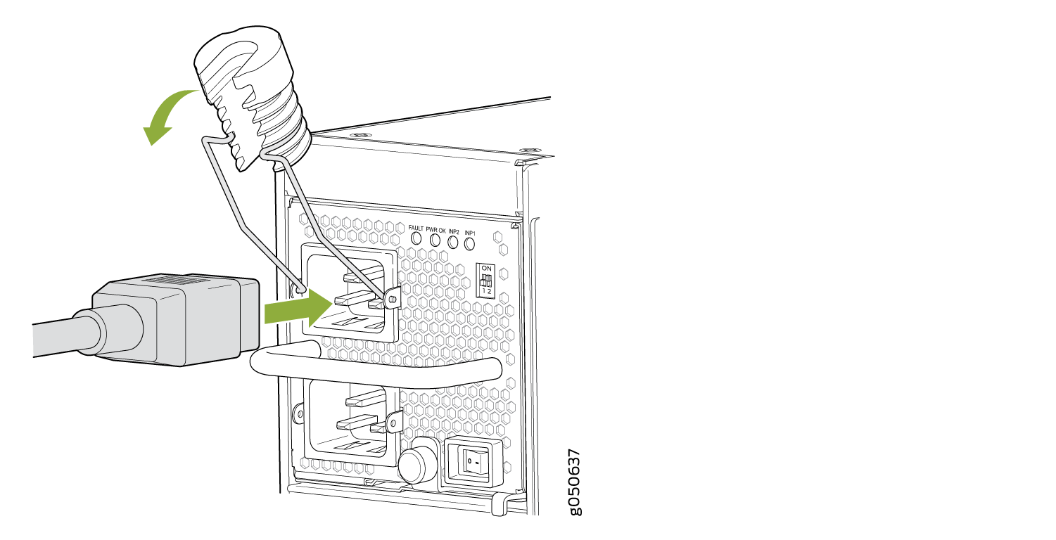
Each QFX10000-PWR-AC power supply comes with two power cord retainers that hold the power cords in place. See Figure 2. Each power cord retainer has a clip and an adjustment nut. The ends of the clip hook into the bracket holes on each side of the AC appliance inlet on the faceplate. The adjustment nut holds the power cord in the correct position. For instructions for installing the power cord retainers, see Connect AC Power to a QFX Modular Chassis.
Each power supply connects to the power rail in the switch. The power rail distributes the output power produced by the power supplies to different switch components. Each AC power supply provides power to all the components in the switch.
Each power supply has its own fan and is cooled by its own internal cooling system. Hot air exhausts from the rear of the chassis.
QFX10000-PWR-AC Power Specifications
Table 1 lists the power specifications for the AC power supply used in a QFX10000 modular chassis.
Item |
Specifications |
|---|---|
AC input voltage |
Operating range: 200–240 VAC |
AC input line frequency |
50–60 Hz |
AC input current rating |
16 A |
AC output power |
2700 W |
Table 2 shows the physical specifications for a QFX10000-PWR-AC power supply.
Specification |
Value |
|---|---|
Height |
3.5 in. (8.89 cm) |
Width |
3.6 in. (9.14 cm) |
Depth |
14.4 in. (6.53 cm) |
Weight |
6.8 lb (3.08 kg) |
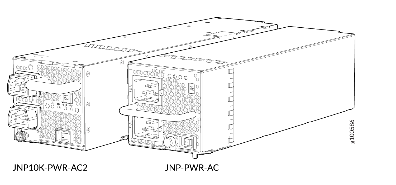
JNP10K-PWR-AC2 Power Supply
The JNP10K-PWR-AC2 power supply is a high-capacity, high-line model that is designed to support either AC or DC systems in either a low-power or high-power mode. The power supply takes AC input and provides DC output of 12.3 VDC, 5000 W with a single feed and 5500 W with a dual feed. For AC systems, the operating input voltage is 180 to 305 VAC and for DC systems, the operating input voltage is 190 to 410 VDC.
The number of power feeds and whether the power supplies provide high output (30-A) or low output (20-A) power is configured using a set of dual inline package (DIP) switches on the faceplate of the power supply. If one power supply in the chassis is set to low power, the power budget for the chassis is reduced to low power, regardless of their DIP switch settings or the output results in CLI. This design safeguards against accidentally setting the power supply to 30-A in a facility that can only provide 20-A and tripping the facility circuit breaker. We recommend that you do not mix DIP switch settings in your system. See Table 3.
The JNP10K-PWR-AC2 power supplies share power.
The JNP10K-PWR-AC2 fits into the standard power supply bay but when compared to most other models, the JNP10K-PWR-AC2 is longer and protrudes from the bay when fully inserted into the chassis. See Figure 3 for the settings for the dip switches.
Extreme burn danger–Do not handle an HVAC or HVDC power supply running in the chassis without heat protective gloves, such as welder’s gloves. The JNP10K-PWR-AC2 can reach temperatures in the range of 158°F (70°C) to 176°F (80°C) under running conditions.
The switch is pluggable type A equipment installed in a restricted-access location. It has a separate protective earthing terminal on the chassis that must be connected to earth ground permanently to ground the chassis adequately and protect the operator from electrical hazards.
Before you begin installing the switch, ensure that a licensed electrician has attached an appropriate grounding lug to the grounding cable that you supply. Using a grounding cable with an incorrectly attached lug can damage the device.
Use a 2-pole circuit breaker rated at 25 A in the building installation and the system, or as per local electrical code.
INP0 (Switch 1) |
INP1 (Switch 2) |
H/L (High Input 30 A/Low Input 20A) |
Output Power |
|---|---|---|---|
On |
On |
On (30 A) |
5500 W |
On |
On |
Off (20 A) |
3000 W |
On |
Off |
On (30 A) |
5000 W |
Off |
On |
On (30 A) |
5000 W |
On |
Off |
Off (20 A) |
2700 W |
Off |
On |
Off (20 A) |
2700 W |
It is important to connect both input feeds of the JNP10K-PWR-AC2 power supply to AC mains before loading the system with power.
The JNP10K-PWR-AC2 requires the enhanced power bus to operate at full power. You can use the standard bus, but available power is 3000 W for power budget from the power management software. To determine whether your system has the standard power bus or the enhanced power bus, see QFX10000 Status Panel.
JNP10K-PWR-AC2 Power Specifications
The JNP10K-PWR-AC2 power supply supports AC, HVAC, and HVDC.
Table 4 lists the power specifications for the JNP10K-PWR-AC power supply.
Item |
Specifications |
|---|---|
AC input voltage |
180–305 VAC |
DC input voltage |
190–410 VDC |
Input current rating |
28.5 A |
DC output power |
12.3 V, 5500 W with dual feed and 5000 W with single feed |
Table 5 shows the physical specifications for a JNP10K-PWR-AC2 power supply.
Specification |
Value |
|---|---|
Height |
3.5 in. (8.89 cm) |
Width |
3.6 in. (9.14 cm) |
Depth |
15.1 in. (38.35 cm) |
Weight |
11.4 lb (5.17 kg) |
QFX10000 Power Cables Specifications
Most sites distribute power through a main conduit that leads to frame-mounted power distribution panels, one of which can be located at the top of the rack that houses the switch. An AC power cord connects each power supply to the power distribution panel.
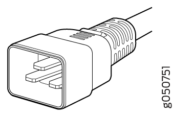
Each detachable AC power cord is 8 feet (approximately 2.5 meters) long. The coupler end of the appliance cord inserts into the AC appliance inlet on the faceplate of the AC power supply. The coupler type is C19 as described by the International Electrotechnical Commission (IEC) standard 60320. The plug end of the power cord fits into the power source outlet that is standard for your geographical location.
In North America, AC power cords must not exceed 15 feet (approximately 4.5 meters) in length, to comply with National Electrical Code (NEC) Sections 400-8 (NFPA 75, 5-2.2) and 210-52 and Canadian Electrical Code (CEC) Section 4-010(3). The cords shipped with the switch to North America and Canada are in compliance.
QFX10000 AC, high-voltage alternating current (HVAC), and high-voltage direct current (HVDC) have specific cord requirements. Use the following sections to determine the cable requirements based on the model of your power supply and any mode settings:
QFX10000-PWR-AC see QFX10000-PWR-AC Power Cable Specifications
JNP10K-PWR-AC2 with 20-A input, see JNP10K-PWR-AC2 Power Cable Specifications
JNP10K-PWR-AC2 with 30-A input, see JNP10K-PWR-AC2 Power Cable Specifications for 30-A Input
- QFX10000-PWR-AC Power Cable Specifications
- JNP10K-PWR-AC2 Power Cable Specifications
- JNP10K-PWR-AC2 Power Cable Specifications for 30-A Input
QFX10000-PWR-AC Power Cable Specifications
Table 6 lists the AC power cord specifications for QFX10000-PWR-AC for various countries and regions.
Country/Region |
Electrical Specifications |
Plug Standards |
Juniper Model Number |
Graphic |
|---|---|---|---|---|
Argentina |
250 VAC, 16 A, 50 Hz |
IRAM Type RA/3/20 |
CBL-EX-PWR-C19-AR |
 |
Australia |
250 VAC, 15 A, 50 Hz |
AS/NZS 3112 Type SAA/3/15 |
CBL-EX-PWR-C19-AU |
 |
Brazil |
250 VAC, 16 A, 50 Hz |
NBR 14136: 2002 Type BR/3/20 |
CBL-EX-PWR-C19-BR |
 |
China |
250 VAC, 16 A, 50 Hz |
GB 1002 Type PRC/3/16 |
CBL-EX-PWR-C19-CH |
 |
Europe (except Italy, Switzerland, and United Kingdom) |
250 VAC, 16 A, 50 Hz |
CEE (7) VII Type VIIG |
CBL-EX-PWR-C19-EU |
 |
India |
250 AC, 16 A, 50 Hz |
SABS 164/1:1992 Type ZA/3 |
CBL-EX-PWR-C19-SA |
 |
Israel |
250 AC, 16 A, 50 Hz |
SI 32/1971 Type IL/3 |
CBL-EX-PWR-C19-IL |
 |
Italy |
250 VAC, 16 A, 50 Hz |
CEI 23-16 Type I/3/16 |
CBL-EX-PWR-C19-IT |
 |
Japan |
250 VAC, 16 A, 60 Hz |
NEMA 6–20 Type N6/20 |
CBL-EX-PWR-C19-JP (default) |
 |
250 VAC, 16 A, 60 Hz |
NEMA L6–20P Type NEMA Locking |
CBL-EX-PWR-C19-JPL |
 |
|
Korea |
250 VAC, 16 A, 50 Hz |
CEE (7) VII Type VIIG |
CBL-EX-PWR-C19-KR |
|
North America |
250 VAC, 16 A, 60 Hz |
NEMA 6–20 Type N6/20 |
CBL-EX-PWR-C19-US (default) |
|
250 VAC, 16 A, 60 Hz |
NEMA L6–20P Type NEMA Locking |
CBL-EX-PWR-C19-USL |
|
|
South Africa |
250 VAC, 16 A, 50 Hz |
SABS 164/1:1992 Type ZA/3 |
CBL-EX-PWR-C19-SA |
 |
Switzerland |
250 VAC, 16 A, 50 Hz |
SEV 5934/2 Type 23G |
CBL-EX-PWR-C19-SZ |
 |
United Kingdom |
250 VAC, 13 A, 50 Hz |
BS 1363/A Type BS89/13 |
CBL-EX-PWR-C19-UK |
|
Worldwide |
250 VAC, 16 A, 50 Hz |
EN 60320-2-2/1 |
CBL-EX-PWR-C19-C20 |
 |
JNP10K-PWR-AC2 Power Cable Specifications
The JNP10K-PWR-AC2 power supply operates in two modes:
30-A input with 5500 W output
JNP10K-PWR-AC2 Power Cable Specifications for 30-A Input shows the cables and connectors for 30-A input.
20-A input with 3000 W output
Table 7 shows the cables appropriate for 20-A input.
-
HVAC input with 3000 W output
Table 8 shows the cable appropriate for HVAC input.
Do not run JNP10K-PWR-AC2 power supplies using 20-A cables if connected to 30-A input.
|
Locale |
Cord Set Rating |
Plug Standards |
Spare Juniper Model Number |
Graphic |
|---|---|---|---|---|
|
Argentina |
16 A, 250 VAC |
IRAM 2073 Type RA/3 |
CBL-JNP-SG4-AR |
|
|
Australia and New Zealand |
15 A, 250 VAC |
AS/NZS 4417 |
CBL-JNP-SG4-AU |
|
|
Brazil |
16 A, 250 VAC |
NBR 14136 Type BR/3 |
CBL-JNP-SG4-BR |
|
|
China |
16 A, 250 VAC |
GB2099 |
CBL-JNP-SG4-CH |
|
|
Europe (except Italy, Switzerland, and United Kingdom) |
20 A, 250 VAC |
IEC 316P6W |
CG_CBL-APP-400-02 |
|
|
Great Britain |
13 A, 250 VAC, |
BS1363 |
CBL-JNP-SG4-UK |
|
|
India |
16 A, 250 VAC |
SANS 164/1 |
CBL-JNP-SG4-SA |
|
|
Israel |
16 A, RA, 250 VAC |
SI 32/1971 Type IL/3G |
CBL-JNP-SG4-IL |
|
|
Italy |
16 A, 250 VAC |
CEI 23-16 |
CBL-JNP-SG4-IT |
|
|
North America |
20 A, 250 VAC |
C20 to Anderson 3-5958p4 |
CBL-JNP-SG4-C20 |
|
|
North America |
16 A, 250 VAC |
Locking NEMA L6-20P |
CBL-JNP-SG4-US-L |
|
|
North America |
16 A, 250 VAC |
NEMA 6-20P |
CBL-JNP-SG4-US |
|
|
North America |
20 A, 250 V |
IEC 320P6W |
CG_CBL-APP-400-02 |
|
|
South Africa |
16 A, 250 VAC |
SANS 164/1 |
CBL-JNP-SG4-SA |
|
|
Switzerland |
16 A, 250 VAC |
CEI 23-50 |
CBL-JNP-SG4-SZ |
|
|
Locale |
Cord Set Rating |
Plug Standards |
Spare Juniper Model Number |
Graphic |
|---|---|---|---|---|
|
North America |
16 A, 277 V |
NEMA L7-20P |
CBL-JNP-SG4-HVAC |
|
JNP10K-PWR-AC2 Power Cable Specifications for 30-A Input
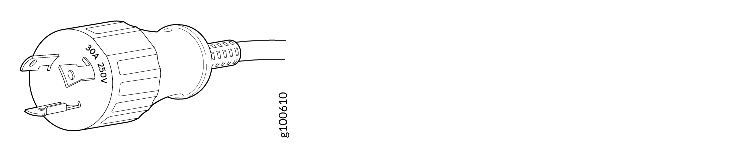
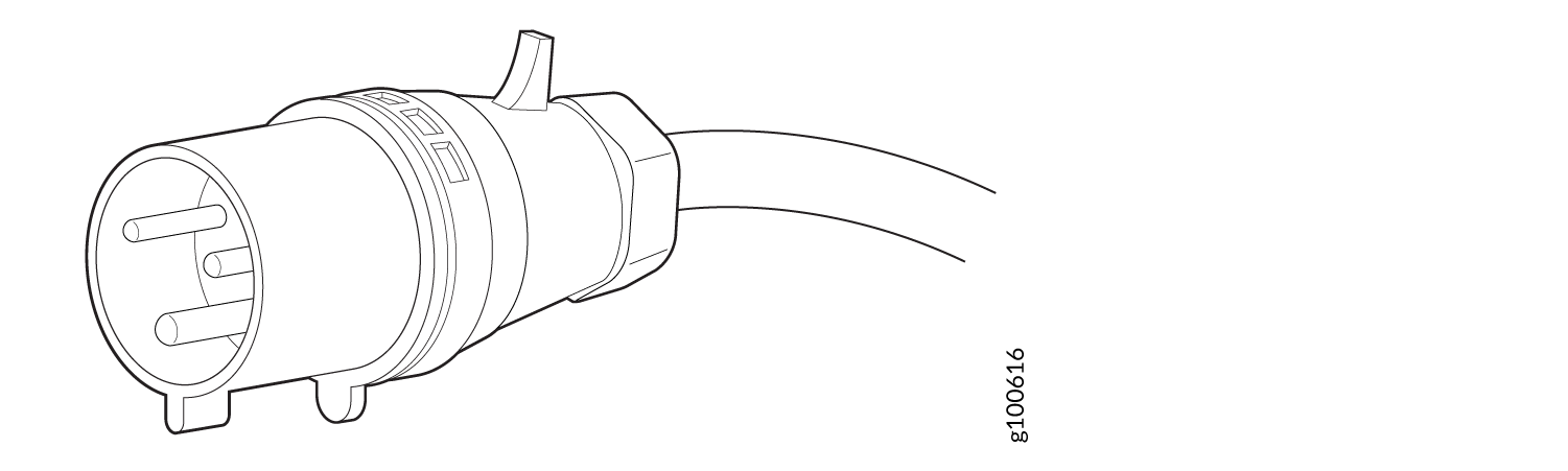
The JNP10K-PWR-AC2 HVAC or HVDC power supplies requires a high voltage cable assembly when set for 30-A input. One end of the cable has an Anderson APP-400 connector, the other end of the cable is bare wire. See Figure 4 and Table 9. These cables are separately orderable and are not shipped automatically with JNP10K-PWR-AC2 orders. An example of the right-angle cable and connector is shown in Figure 6.
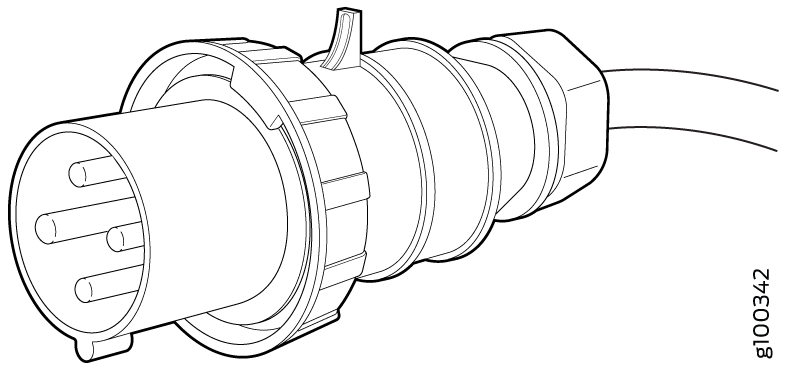
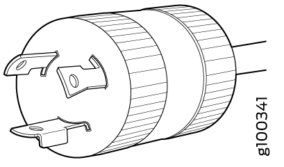
For connection to AC systems, Juniper provides a cable with either a NEMA 30-A connector (Figure 4) or an IEC 330P6W connector (Figure 5).
Power Cord |
Locale |
Cord Set Rating |
Plug Standards |
Connector |
Spare Juniper Model Number |
|---|---|---|---|---|---|
|
HVDC power cord |
Any |
30- A, 400 VAC |
UL 950 and IEC 60950 |
Anderson/straight to bare wire |
CBL-PWR2-BARE |
|
HVDC power cord |
Any |
30-A, 400 VAC |
UL 950 and IEC 60950 |
Anderson/right-angle to bare wire |
CBL-PWR2-BARE-RA |
AC power cord |
Continental Europe |
30-A 250 VAC |
UL 950 and IEC332P6 |
Anderson/straight to IEC 332P6 |
CBL-PWR2-332P6W-RA |
AC power cord |
North America |
30-A 250 VAC |
UL 950 and IEC332P6 |
Anderson/straight to IEC332P6 |
CBL-PWR2-332P6W |
AC power cord |
North America |
30-A 240 VAC |
IEC330P6 |
Anderson/right-angle to IEC 330P6 |
CBL-PWR2-330P6W-RA |
AC power cord |
North America |
30-A 240 VAC |
IEC330P6 |
Anderson/straight to IEC 330P6 |
CBL-PWR2-330P6W |
AC power cord |
North America |
30-A 250 VAC |
UL 498, IEC5958P4 |
Anderson/straight to L6-30P |
CBL-PWR2-L6-30P |
AC jumper power cord |
North America |
30-A 400 VAC |
UL, CSA |
Anderson/straight to Anderson |
CG-CBL-APP-400-02 |
AC power cord |
North America |
30-A 250 VAC |
UL 498, CSA |
Anderson/right-angle to L6-30P |
CBL-PWR2-L6-30P-RA |
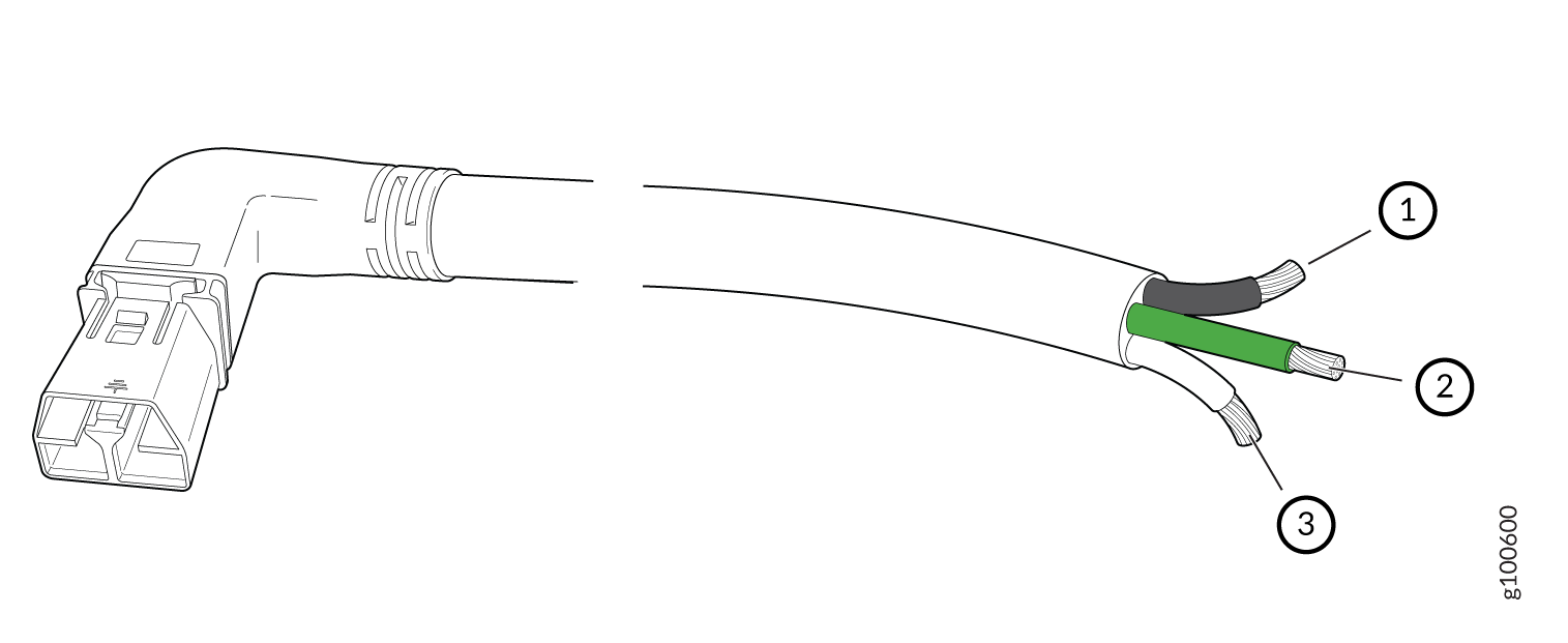
1 — Black wire–Return (+) | 3 — White wire–Neutral |
2 — Green wire-Ground |
See Also
QFX10000 AC Power Supply LEDs
The QFX10000-PWR-AC power supply has four LEDs on its faceplate: INP1, INP2, PWR OK, and FAULT. These LEDs display information about the status of the power supply. See Figure 7.
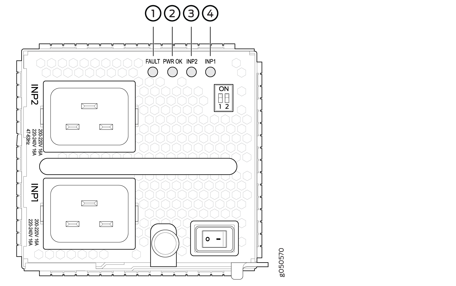
1 — FAULT | 3 — INP2–Source input 2 |
2 — PWR OK | 4 — INP1–Source input 1 |
Table 10 describes the LEDs on a QFX10000-AC power supply in QFX10008 and QFX10016 modular chassis.
LED |
Color |
State |
Description |
|---|---|---|---|
INP1 (INP0 in CLI output) or INP2 (INP1 in CLI output) |
Yellow |
Blinking |
Indicates that the AC power input voltage is not within normal operating range. |
Green |
Solid |
AC is within operating range (200–240 VAC). |
|
Dark |
Unlit |
The power supply is switched off. |
|
PWR OK |
Green |
Solid |
DC power output is within normal operating range. |
Yellow |
Blinking |
The output is out of the limits. |
|
FAULT |
Dark |
Unlit |
Power supply is functioning normally. |
Red |
Solid |
Power supply has failed and must be replaced. Or, only one input is powered and the enabled switch for the input that is not powered is set to ON. See Connect AC Power to a QFX Modular Chassis for more information about the enable switches. |
If the INP1 or INP2 LED and the PWR OK LED are unlit, the AC power cord is not installed properly or the power supply has failed.
If the INP1 or INP2 LED is lit and the PWR OK LED is unlit, the AC power supply is not installed properly or the power supply has an internal failure.
See Also
JNP10K-PWR-AC2 Power Supply LEDs
The JNP10K-PWR-AC2 power supply has four LEDs on its faceplate: !, OK, 2, and 1. These LEDs display information about the status of the power supply. See Figure 8.
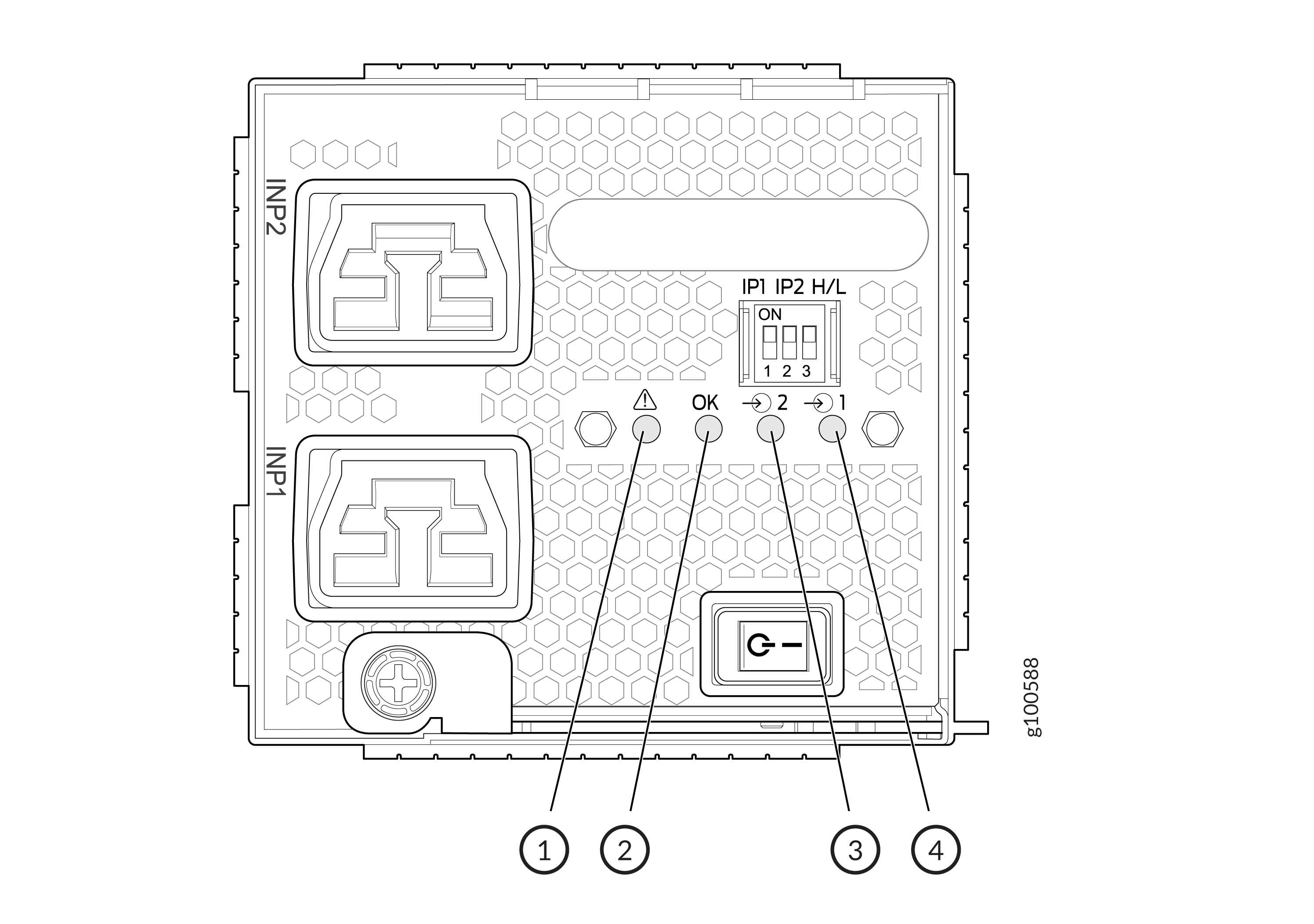
1 — ! FAULT | 3 — 2 INP2–Source input 1 |
2 — OK PWR OK | 4 — 1 INP1–Source input 0 |
Physical markings on the power supply are INP1 and INP2.
These markings correspond to INP0 and INP1 in the show chassis
power output (see Table 11).
Physical Marking on JNP10K-PWR-AC2 |
Show Chassis Power Command |
|---|---|
INP1 |
INP0 |
INP2 |
INP1 |
Table 12 describes the LEDs on a JNP10K-PWR-AC2 power supply.
LED |
Color |
State |
Description |
|---|---|---|---|
INP1 or INP0 in CLI output |
Yellow |
Blinking |
The input voltage is present, but is not within normal operating range. |
Green |
Solid |
The input voltage is present and within normal operating range. |
|
Unlit |
Off |
The power supply is switched off; voltage is zero. |
|
INP2 or INP1 in CLI output |
Yellow |
Blinking |
The input voltage is present, but is not within normal operating range. |
Green |
Solid |
The input voltage is present and within normal operating range. |
|
Unlit |
Off |
The power supply is switched off; voltage is zero. |
|
OK |
Green |
Solid |
The power supply output is within normal operating range. |
Yellow |
Blinking |
The power supply output is out of the power limits or is over-current position. |
|
! |
Red |
Solid |
Power supply has failed and must be replaced. |
Unlit |
Off |
Power supply is functioning normally. |