ON THIS PAGE
Maintaining QFX10000 Power System
QFX10008 and QFX10016 routers support both AC and DC power supplies. Additionally, QFX10000 routers support high voltage alternating current (HVAC) or high voltage direct current (HVDC) power supplies. To install and remove the power supplies in a QFX10008 router or a QFX10016 router, refer to the following sections.
How to Remove a QFX10000-PWR-AC Power Supply
Before you remove a power supply from the chassis:
Ensure you understand how to prevent ESD damage. See Prevention of Electrostatic Discharge Damage.
Ensure that you have the following parts and tools available to remove an QFX10000-PWR-AC power supply from a QFX10000 switch:
Electrostatic discharge (ESD) grounding strap
Phillips (+) screwdriver, number 1
Replacement power supply or a cover for the power supply slot
The QFX10000-PWR-AC power supply in a QFX10008 and QFX10016 switch chassis is a hot-removable and hot-insertable field-replaceable unit (FRU). You remove all power supplies from the rear of the chassis.
Before you remove a power supply, ensure that you have power supplies sufficient to power the switch left in the chassis. See Power Requirements for QFX10000 Components.
Do not leave the power supply slot empty for a long time while the switch is operational. Either replace the power supply promptly or install a cover over the empty slot.
To remove a QFX10000-PWR-AC power supply from a QFX10000 switch:
- Attach the electrostatic discharge (ESD) grounding strap
to your bare wrist, and connect the strap to the ESD point on the
chassis. There is an ESD point located next to the protective earthing
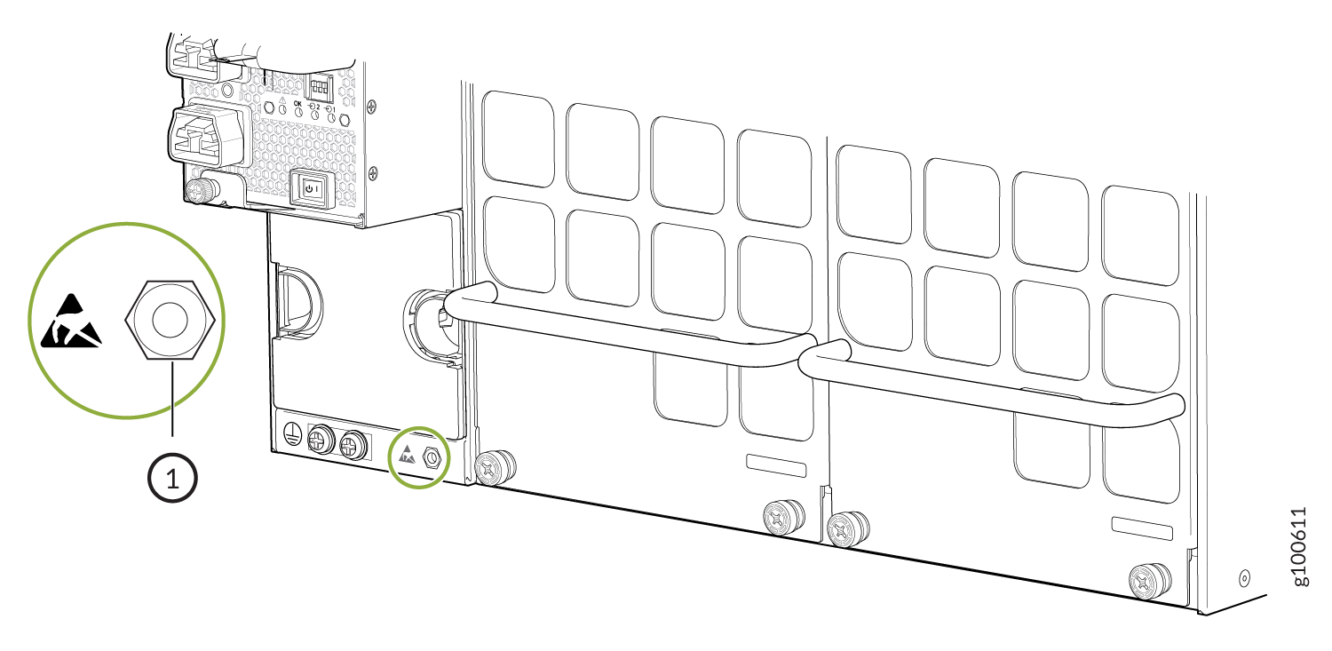
terminal and below PSU 5 on the QFX10008
rear panel (see Figure 1) and
below PSU_9 on the QFX10016 (see Figure 2).Figure 1: ESD Point on QFX10008 Chassis Rear
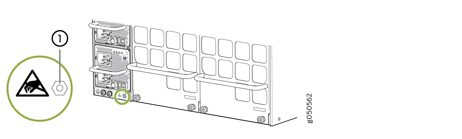 1—
1—ESD point
Figure 2: ESD Point on QFX10016 Chassis Rear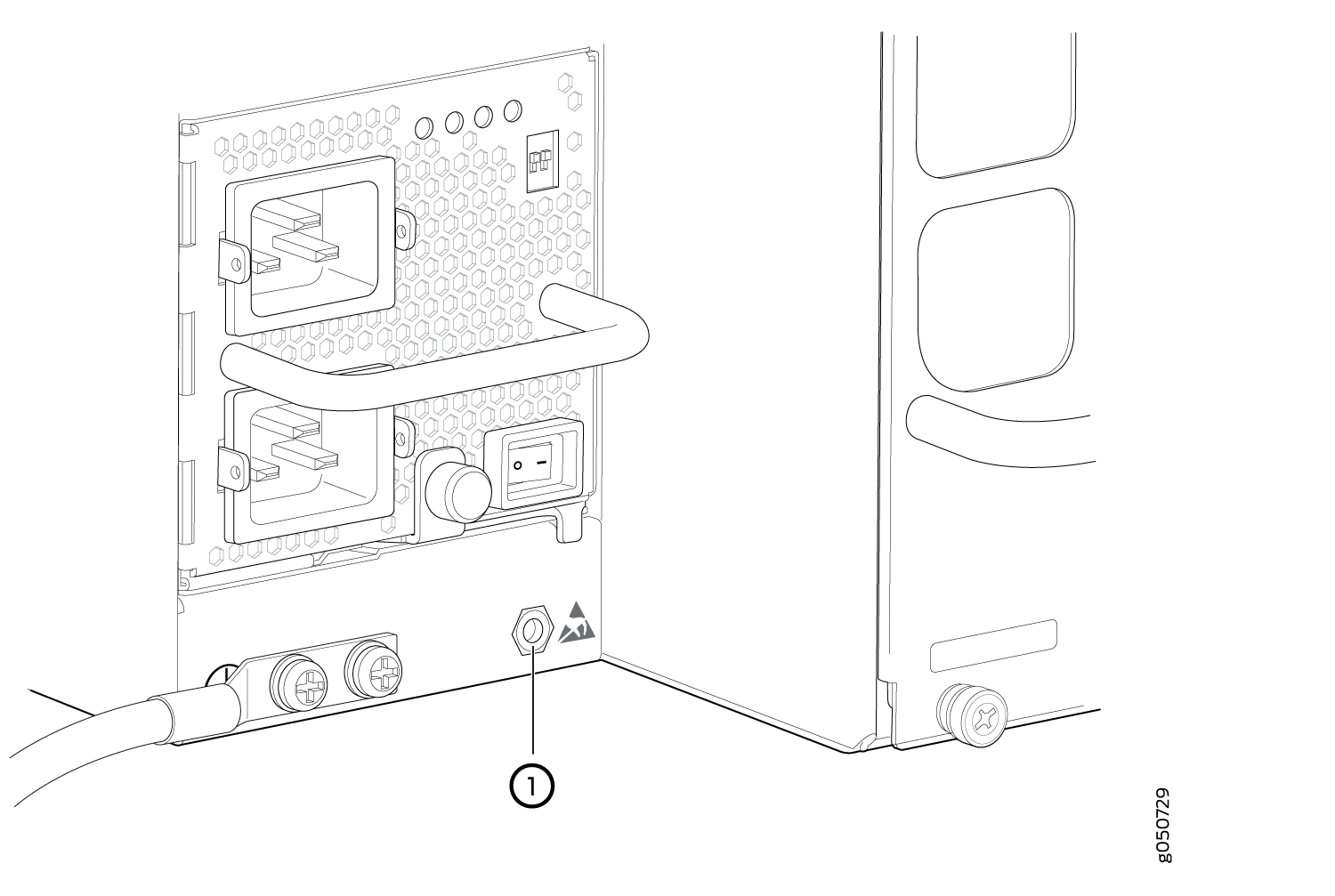 1—
1—ESD point
How to Install a QFX10000-PWR-AC Power Supply
Before you install an QFX10000-PWR-AC power supply in the switch:
Ensure you understand how to prevent ESD damage. See Prevention of Electrostatic Discharge Damage.
If the AC power source outlets have a power switch, set them to the off (O) position.
Ensure that you have the following parts and tools available to install a QFX10000-PWR-AC power supply:
Electrostatic discharge (ESD) grounding strap
Phillips (+) screwdriver, number 1
Power cords appropriate for your geographical location. See QFX10000 Power Cables Specifications.
Power cord retainer clips
The QFX10000-PWR-AC power supply is a hot-insertable and hot-removable field-replaceable unit (FRU). You can install up to 6 QFX10000-PWR-AC power supplies in a QFX10008 and 10 in a QFX10016 switch chassis. All power supplies install in the rear of the chassis in the slots provided along the left side.
Do not mix AC and DC power supplies in the same chassis.
To install a QFX10000-PWR-AC power supply in a QFX10008 or QFX10016:
- Attach the electrostatic discharge (ESD) grounding strap
to your bare wrist, and connect the strap to the ESD point on the
chassis. There is an ESD point located next to the protective earthing
terminal and below PSU 5 on the QFX10008
rear panel (see Figure 5) or
below PSU_9 on the QFX10016 (see Figure 6).Figure 5: ESD Point on QFX10008 Chassis Rear1—
ESD point
Figure 6: ESD Point on QFX10016 Chassis Rear1—ESD point
- If the power supply slot has a cover panel, insert your
thumb and forefinger into the finger holes, squeeze and pull the cover
panel out of the slot. Save the cover panelfor later use. See Figure 7 for removal on a QFX10008
and Figure 8 for the QFX10016.Figure 7: Removing the PSU Cover Panel on a QFX10008
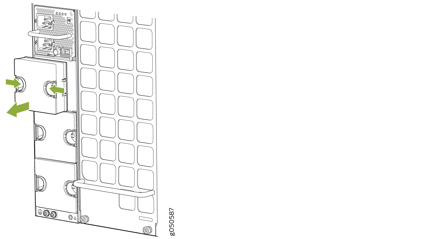 Figure 8: Removing the PSU Cover Panel on a QFX10016
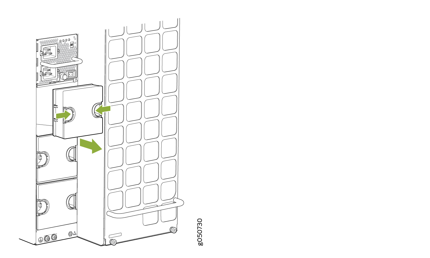
-
Tighten the captive screw by turning it clockwise by using your fingers or by
using the Phillips (+) screwdriver, number 1. Do not overtighten—do not apply
more than 7.3 lb-in (0.82 Nm) of torque to the screws. When the screw is
completely tight, the latch locks into the switch chassis.
Figure 9: Installing a QFX10000-PWR-AC Power Supply in a QFX10008
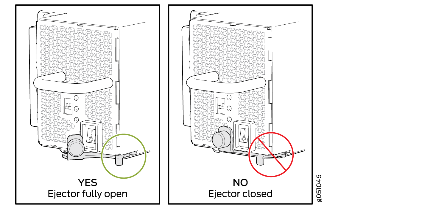
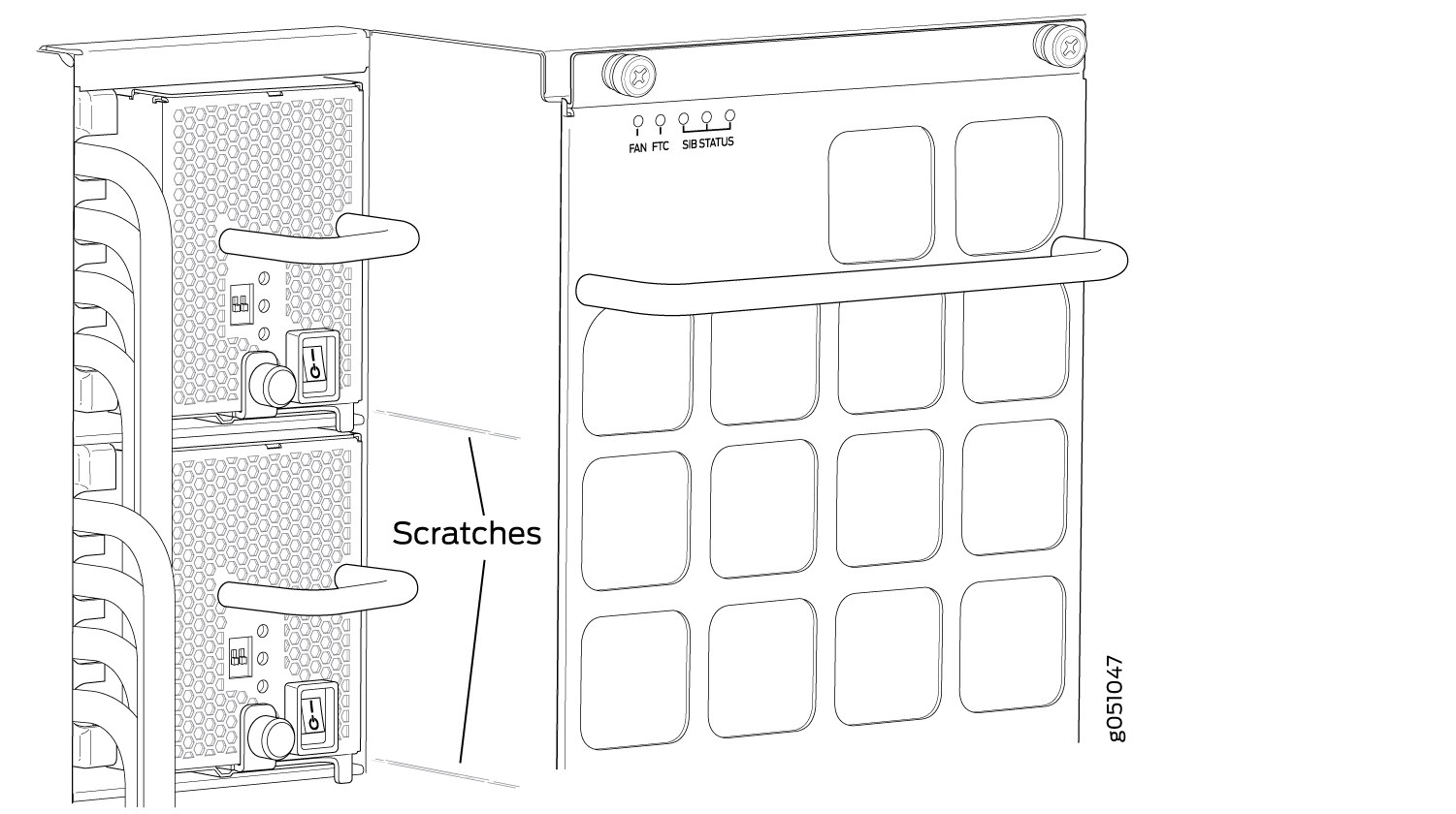
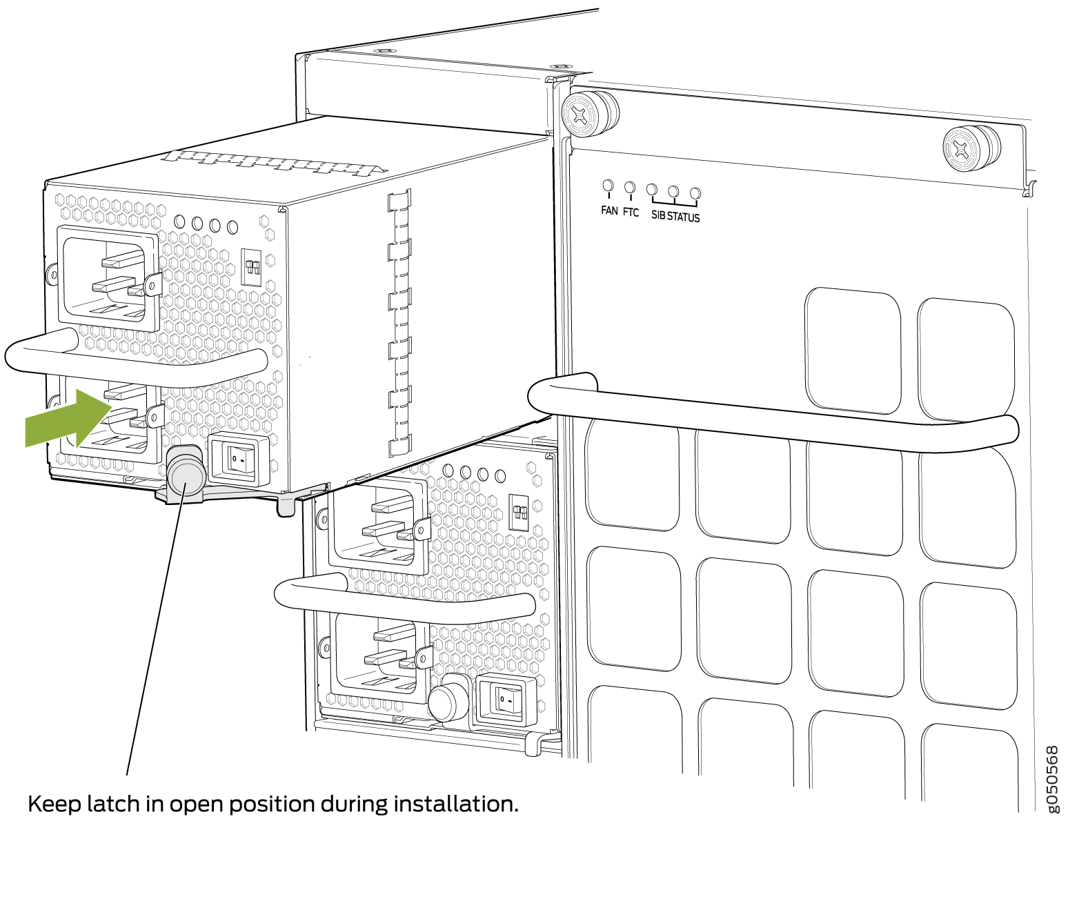 Note:
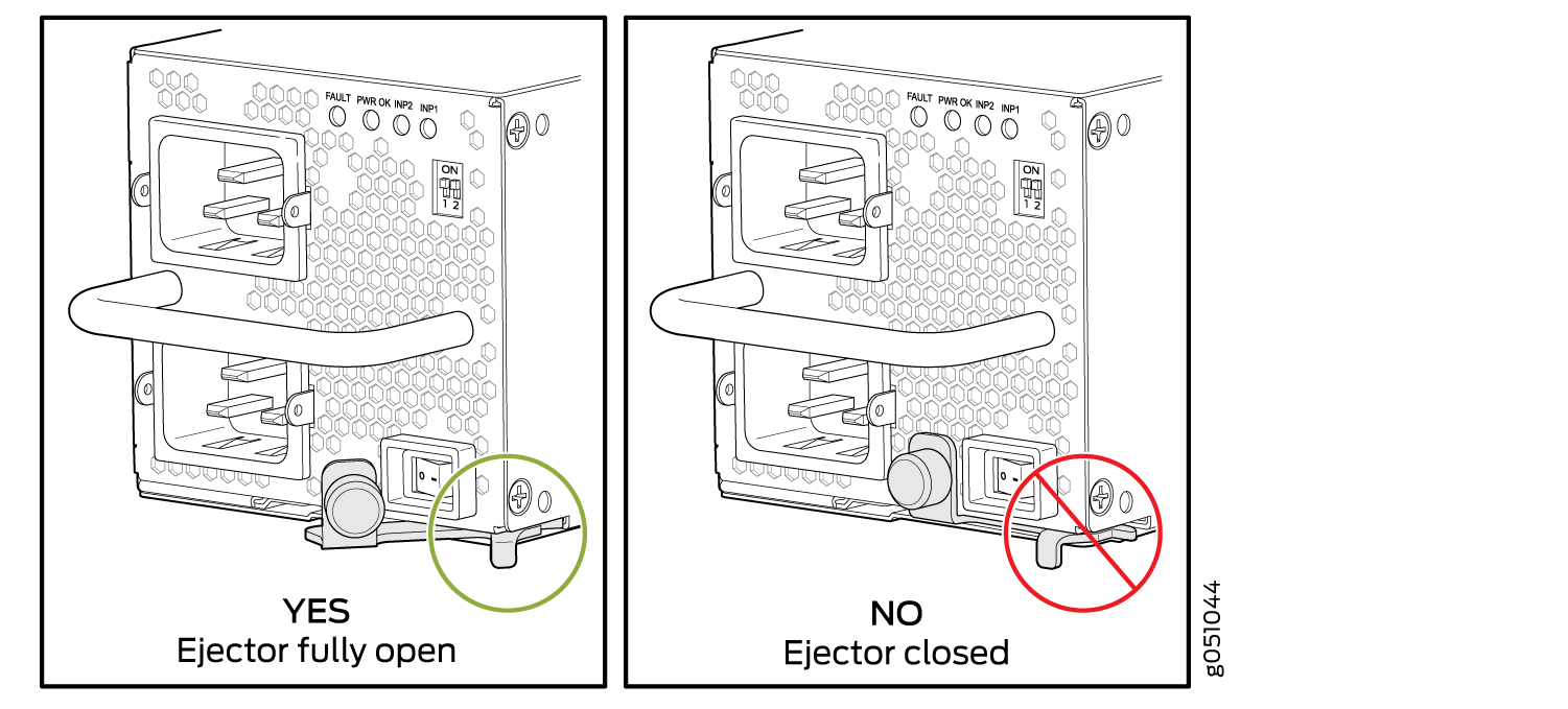
Note:Ensure that the ejector is fully open to avoid scratching the chassis.
Figure 10: Installing a QFX10000-PWR-AC Power Supply in a QFX10016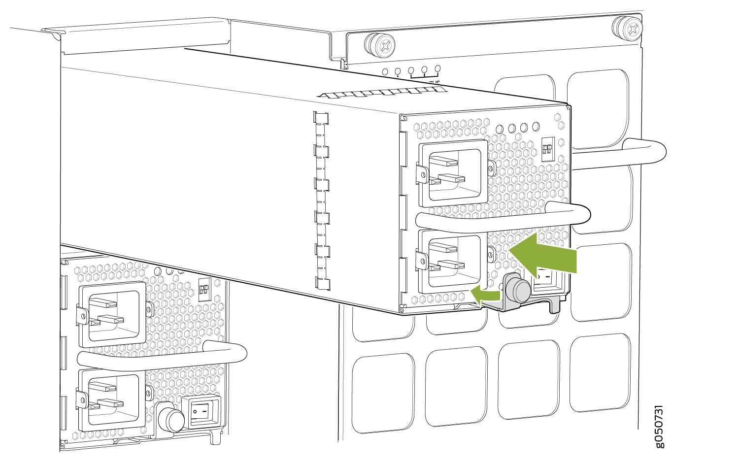
- Manually load balance the power supplies as you attach
each power cable to a dedicated AC power source outlet. To load balance,
route the power cables to alternate between power sources. The QFX10000-PWR-AC
does not share power; all power comes into INP1 (lower receptacle)
and only uses INP2 (top receptacle) at fail over. See Figure 11 for QFX10008 and Figure 12.Figure 11: Proper Load Balancing for QFX10000-PWR-AC Power Cables on QFX10008
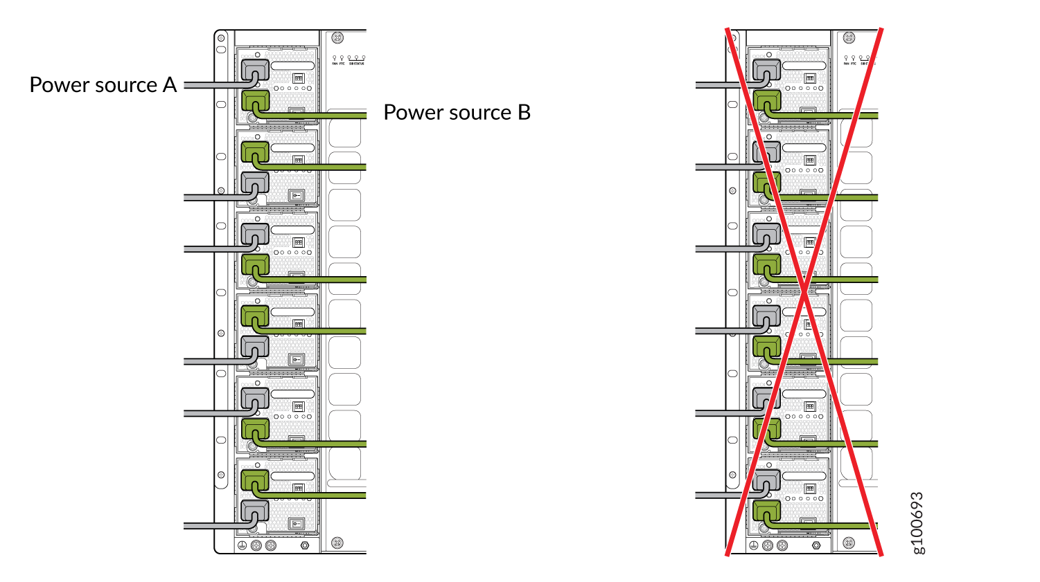 Figure 12: Proper Load Balancing for QFX10000-PWR-AC Power Cables on QFX10016
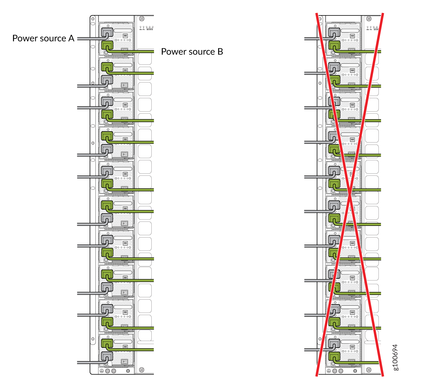 Warning:
Ensure that the power cords do not block access to router components or drape where people can trip on them. Always prevent cords and cables from being exposed to hot air exhaust by routing them away from the fan trays and power supplies at the rear of the chassis.
- Fasten the cord retainer by lowering the clip over the
cord and pushing the cord into the adjustment nut of the cord retainer.
Rotate the nut until it is tight against the base of the cord. See Figure 13.Figure 13: Power Cord and Retainer Clip
 1—
1—Enable switch for INP1
2—Enable switch for INP2
Warning:Ensure that the power cords do not block access to switch components or drape where people can trip on them.
See Also
How to Remove a JNP10K-PWR-AC2 Power Supply
Before you remove an JNP10K-PWR-AC2 power supply from the chassis:
Ensure you understand how to prevent ESD damage. See Prevention of Electrostatic Discharge Damage.
Ensure that you have the following parts and tools available to remove a JNP10K-PWR-AC2 power supply from a QFX10000 switch:
Heat protective gloves able to withstand temperatures in the range of 158°F (70°C) to 176°F (80°C)
Electrostatic discharge (ESD) grounding strap
Phillips (+) screwdriver, number 1
Replacement power supply or a cover panel for the power supply slot
The JNP10K-PWR-AC2 power supply in a QFX10008 or a QFX10016 chassis is a hot-removable and hot-insertable field-replaceable unit (FRU). You remove all power supplies from the rear of the chassis.
Protect yourself from severe burns by wearing heat-protective gloves when removing a working QFX10000-PWR-AC2 power supply from the chassis. These power supplies can reach in the range of 158°F (70°C) to 176°F (80°C).
Before you remove a power supply, ensure that you have power supplies sufficient to power the switch left in the chassis. See Power Requirements for QFX10000 Components.
Do not leave the power supply slot empty for a long time while the switch is operational. Either replace the power supply promptly or install a cover panel over the empty slot.
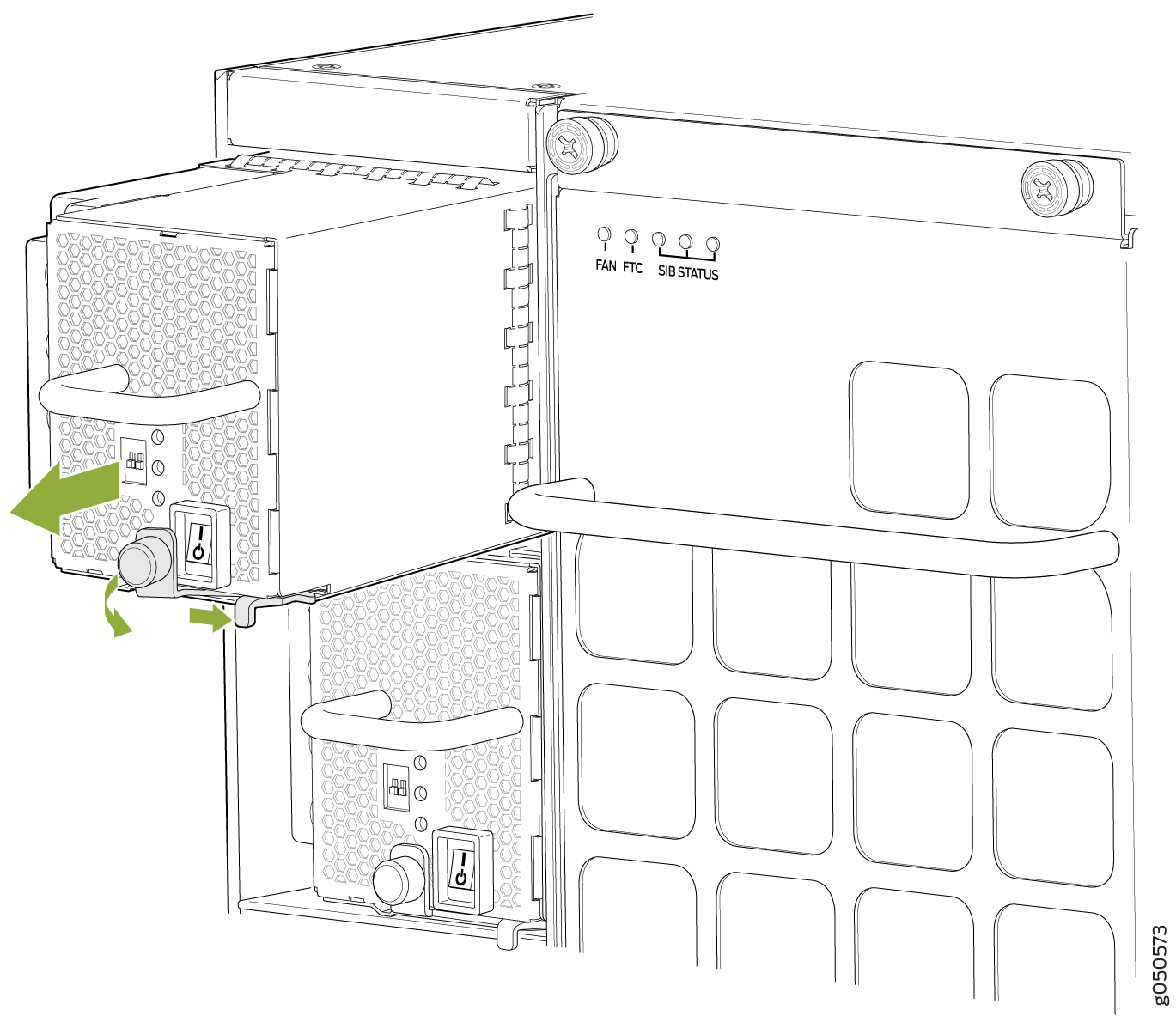
To remove a JNP10K-PWR-AC2 power supply from a QFX10000 switch:
- Attach the electrostatic discharge (ESD) grounding strap
to your bare wrist, and connect the strap to the ESD point on the
chassis. There is an ESD point located next to the protective earthing
terminal and below PSU 5 on the QFX10008
rear panel (see Figure 14) and
below PSU_9 on the QFX10016 (see Figure 15).Figure 14: ESD Point on QFX10008 Chassis Rear
 1—
1—ESD point
Figure 15: ESD Point on QFX10016 Chassis Rear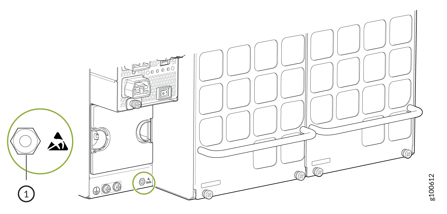 1—
1—ESD point
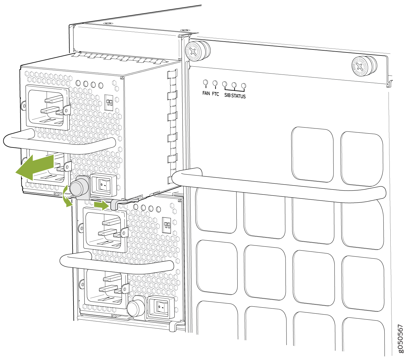
-
Unscrew the captive screw counterclockwise by using your fingers or by
using the Phillips (+) screwdriver, number 1. See Figure 16 and Figure 17.
Figure 16: Removing a JNP10K-PWR-AC2 from a QFX10008 Chassis
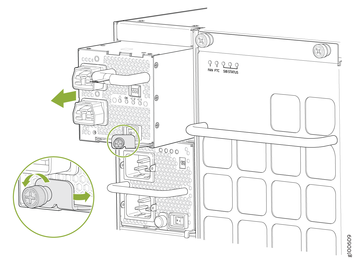 Figure 17: Removing a JNP10K-PWR-AC2 from a QFX10016 Chassis
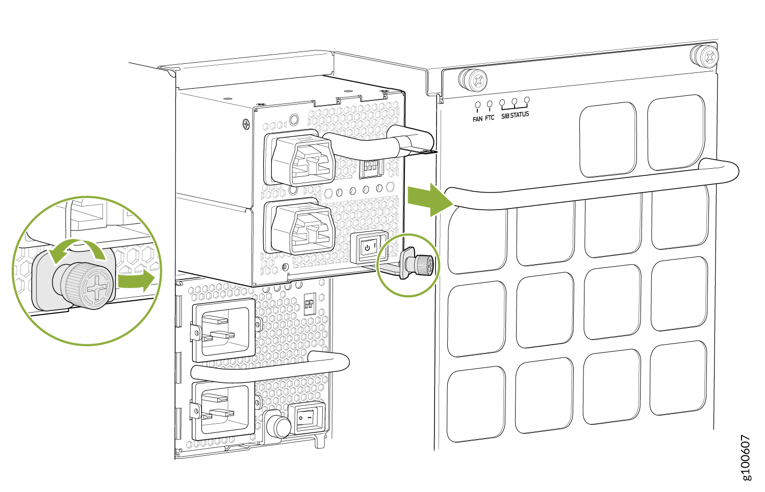
How to Install a JNP10K-PWR-AC2 Power Supply
The JNP10K-PWR-AC2 power supply in a QFX10008 or a QFX10016 chassis is a hot-insertable and hot-removable field-replaceable unit (FRU). You can install up to 6 JNP10K-PWR-AC2 power supplies in a QFX10008 and 10 in a QFX10016 switch chassis. All power supplies install in the rear of the chassis in the slots provided along the left side.
Do not mix AC and DC power supplies in the same running chassis. You may have both QFX10000-PWR-AC and JNP10K-PWR-AC2 in the same chassis while swapping out one type of power supply for the other.
Protect yourself from severe burns by wearing heat-protective gloves when removing a running JNP10K-PWR-AC2 power supply from the chassis. The power supply can reach in the range of 158°F (70°C) to 176°F (80°C).
Before you install a JNP10K-PWR-AC2 power supply in the chassis:
Ensure that you have followed all safety warnings and cautions:
Ensure you understand how to prevent ESD damage. See Prevention of Electrostatic Discharge Damage.
If the AC or DC power source outlets have a power switch, set them to the off (O) position.
Ensure that you have the following parts and tools available to install an JNP10K-PWR-AC2 power supply:
Electrostatic discharge (ESD) grounding strap
Phillips (+) screwdriver, number 1
Power cables appropriate for your geographical location (for low voltage installations) or input amperage (for high voltage installations). See QFX10000 Power Cables Specifications. HVAC and HVDC connectors and lugs must be installed by a qualified electrician before installation.
To install a JNP10K-PWR-AC2 power supply in a QFX10008 or a QFX10016:
- Attach the electrostatic discharge (ESD) grounding strap
to your bare wrist, and connect the strap to the ESD point on the
chassis. There is an ESD point located next to the protective earthing
terminal and below PSU5 on the QFX10008 rear
panel (see Figure 18) or below PSU9 on the QFX10016 (see Figure 19).Figure 18: ESD Point on the QFX10008 Chassis Rear1—
ESD point
Figure 19: ESD Point on QFX10016 Chassis Rear1—ESD point
- If the power supply slot has a cover panel on it, insert
your thumb and forefinger into the finger holes, squeeze, and pull
the cover out of the slot. Save the cover panel for later use. See Figure 20 for removal on a QFX10008
and Figure 21 for the QFX10016.Figure 20: Removing the Power Supply Cover Panel on a QFX10008
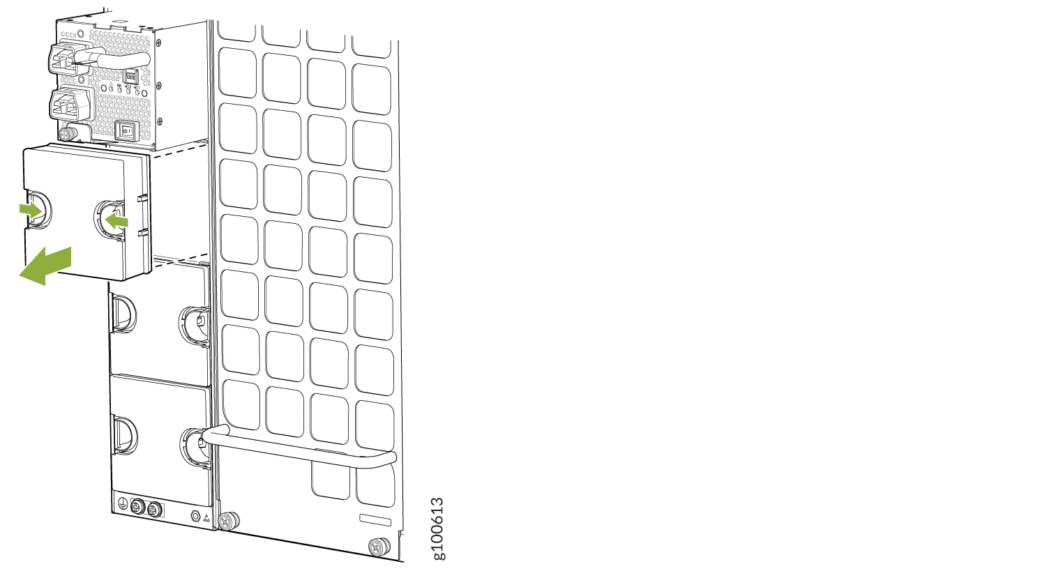 Figure 21: Removing the Power Supply Cover Panel on a QFX10016
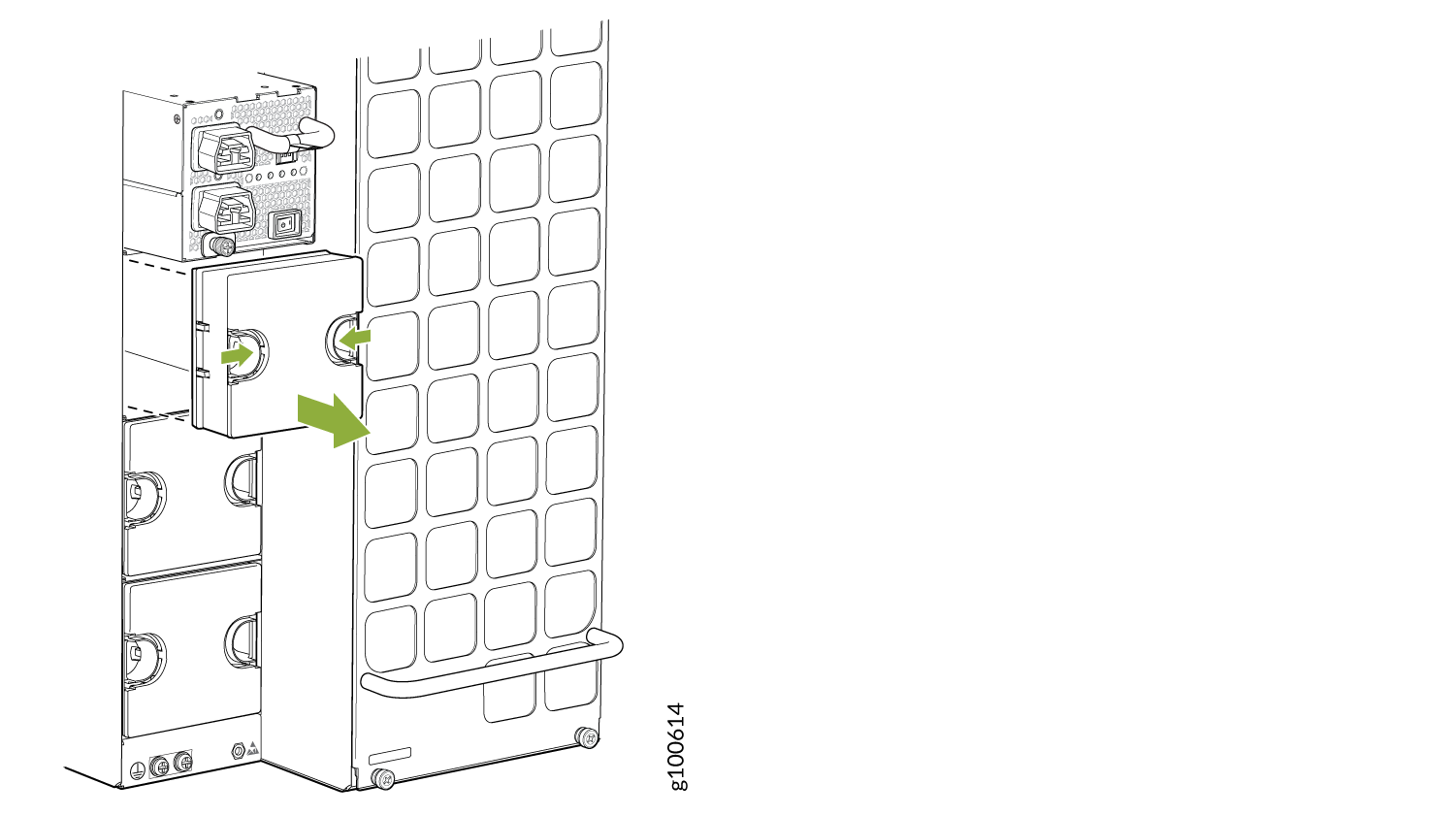
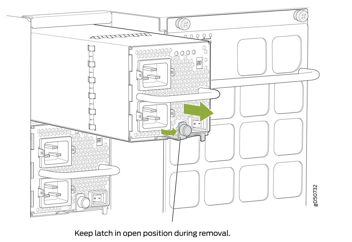
-
Tighten the captive screw by turning it clockwise by using your fingers or
by using the Phillips (+) screwdriver, number 1. When the screw is
completely tight, the latch locks into the switch chassis.
Figure 22: Installing a JNP10K-PWR-AC2 in a QFX10008
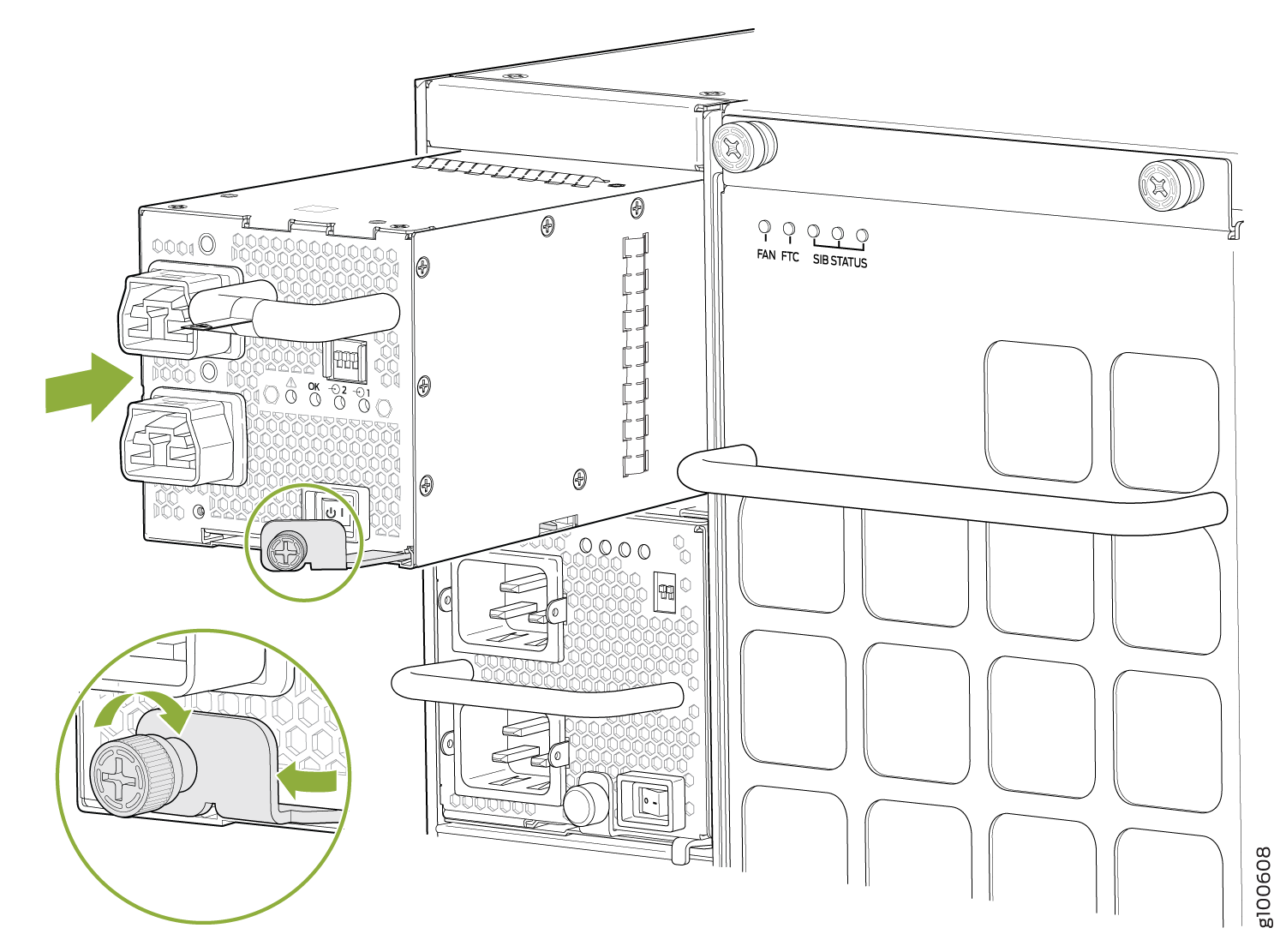 Figure 23: Installing a JNP10K-PWR-AC2 in a QFX10016
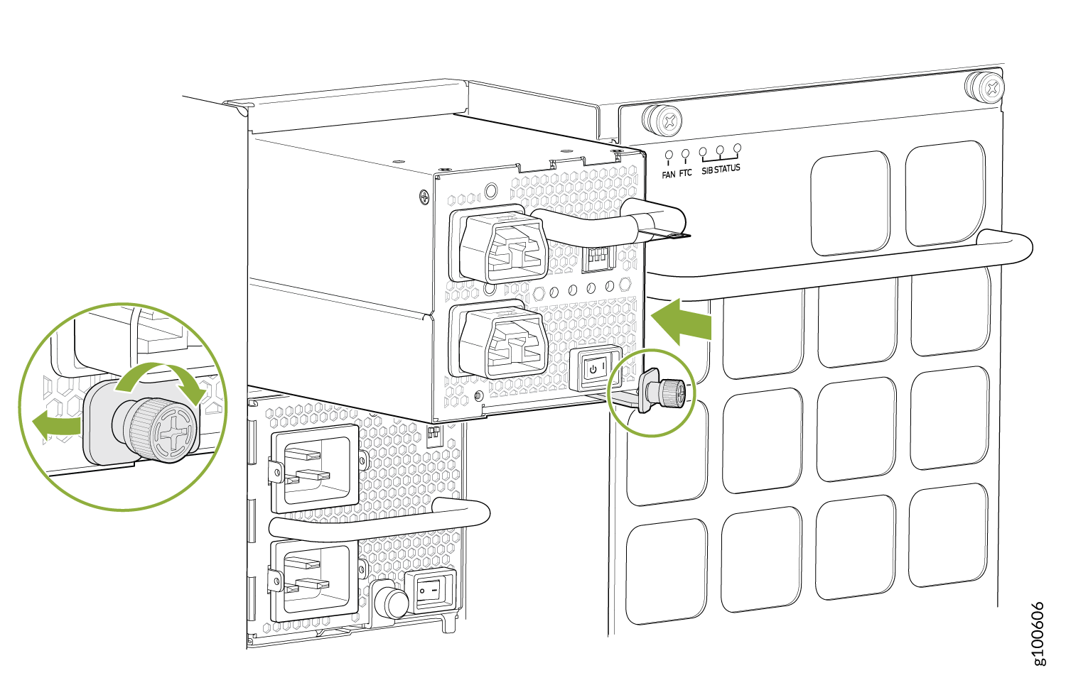
- Attach each power cable to a dedicated power source (A
and B). The JNP10K-PWR-AC2 only requires that each power supply be
connected to a separate source. See Figure 24 for some possible
cabling combinations for QFX10008 and Figure 25 for QFX10016.Figure 24: Proper Load Balancing for QFX10000-PWR-AC2 Power Cables on QFX10008
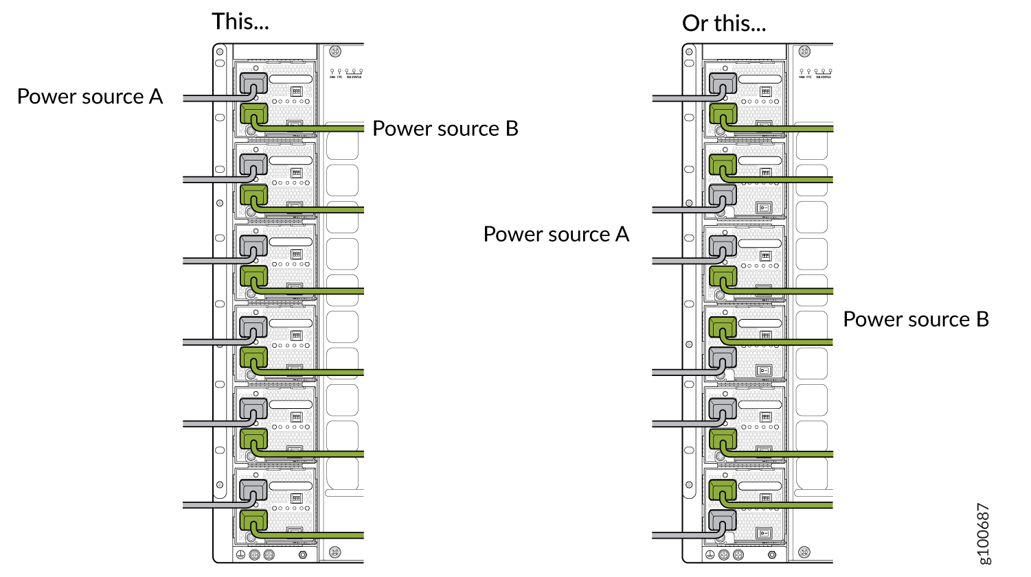 Figure 25: Proper Load Balancing for QFX10000-PWR-AC2 Power Cables on QFX100016
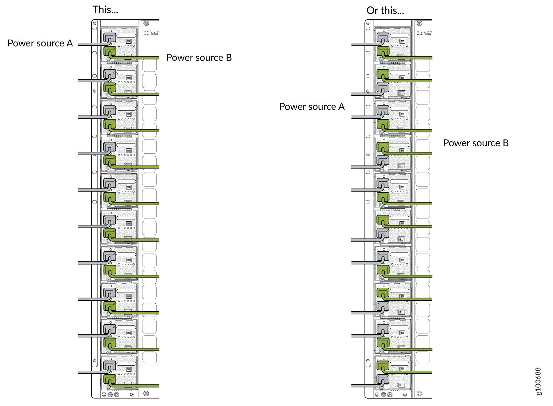
How to Remove a QFX10000-PWR-DC Power Supply
Before you remove a DC power supply from the switch:
Ensure you understand how to prevent ESD damage. See Prevention of Electrostatic Discharge Damage.
Ensure that you have the following parts and tools available to remove a QFX10000-PWR-DC power supply:
Electrostatic discharge (ESD) grounding strap
Phillips (+) screwdriver, numbers 1 and 2
13/32 in. (10 mm) nut driver or socket wrench
Replacement power supply or a cover for the power supply slot
The QFX10000-PWR-DC power supply in a QFX10008 and QFX10016 chassis is a hot-removable and hot-insertable field-replaceable unit (FRU). You remove DC power supplies from the rear of the chassis.
Before you remove a power supply, ensure that you have power supplies sufficient to power the switch left in the chassis. See Power Requirements for QFX10000 Components.
Before performing DC power procedures, ensure that power is removed from the DC circuit. To ensure that all power is off, locate the circuit breaker on the panel board that services the DC circuit, switch the circuit breaker to the OFF position, and tape the switch handle of the circuit breaker in the OFF position.
Do not leave the power supply slot empty for a long time while the switch is operational. Either replace the power supply promptly or install a cover over the empty slot.
To remove a QFX10000-PWR-DC power supply from a QFX10000 switch (see Figure 28):
- Attach the electrostatic discharge (ESD) grounding strap
to your bare wrist, and connect the strap to the ESD point on the
chassis. There is an ESD point located next to the protective earthing
terminal and below PSU 5 on the QFX10008
rear panel (see Figure 26) and below PSU_9 on the QFX10016 (see Figure 27).Figure 26: ESD Point on QFX10008 Chassis Rear1—
ESD point
Figure 27: ESD Point on QFX10016 Chassis Rear1—ESD point
- Taking care not to touch power supply components, pins,
leads, or solder connections, place one hand under the power supply
to support it. Grasp the power supply handle with your other hand
and pull the power supply completely out of the chassis.CAUTION:
See the heat symbol
 . The power supply surfaces are hot. Allow a few minutes for the
power supply to cool by pulling the power supply halfway out of the
chassis, or wear heat-resistant gloves while removing the power supply.
. The power supply surfaces are hot. Allow a few minutes for the
power supply to cool by pulling the power supply halfway out of the
chassis, or wear heat-resistant gloves while removing the power supply.
Ensure that the ejector is fully open to avoid scratching the chassis.
|
|
How to Install a QFX10000-PWR-DC Power Supply
Before you install a QFX10000-PWR-DC power supply in the chassis, ensure that you have followed all safety warnings and cautions:
Before performing DC power procedures, ensure that power is removed from the DC circuit. To ensure that all power is off, locate the circuit breaker on the panel board that services the DC circuit, switch the circuit breaker to the OFF position, and tape the switch handle of the circuit breaker in the OFF position.
Before you connect power to the switch, a licensed electrician must attach a cable lug to the grounding and power cables that you supply. A cable with an incorrectly attached lug can damage the switch (for example, by causing a short circuit).
Do not mix AC and DC power supplies in the same chassis.
To meet safety and electromagnetic interference (EMI) requirements and to ensure proper operation, you must connect QFX10008 switches to earth ground before you connect them to power. For installations that require a separate grounding conductor to the chassis, use the protective earthing terminal on the switch chassis to connect to earth ground. For instructions on connecting a QFX10000 switch to ground using a separate grounding conductor, see Connect the QFX10008 or QFX10016 to Earth Ground.
The battery returns of the QFX10000-PWR-DC power supply must be connected as an isolated DC return (DC-I).
Ensure you understand how to prevent ESD damage. See Prevention of Electrostatic Discharge Damage.
Ensure that you have the following parts and tools available to install a QFX10000-PWR-DC power supply:
Electrostatic discharge (ESD) grounding strap
DC power source cables (not provided) with the cable lugs (provided) attached
The provided terminal lugs in a QFX10000 are sized for either 4 AWG (21.1 mm2) or 6 AWG (13.3 mm2) power source cables. When running all QFX10000-PWR-DC power supply modules in the chassis, the DC power source cables that you provide must be 6 AWG (13.3 2) mm²) stranded wire. We recommend that you install heat-shrink tubing insulation around the crimped section of the power cables and lugs.
Note:If you upgrade the QFX10000-PWR-DC to a JNP10K-PWR-DC2 and set the input mode to high (80-A), you must use 4 AWG (21.1 mm²) stranded wire.
Note:See the heat symbol
.
Wear heat-resistant gloves while accessing the fan tray and power
supply.13/32 in. (10 mm) nut driver or socket wrench
Phillips (+) screwdrivers, numbers 1 and 2
Multimeter
The QFX10000-PWR-DC power supply in QFX10008 and QFX10016 chassis is a hot-removable and hot-insertable field-replaceable unit (FRU). You can install up to 6 QFX10000-PWR-DC power supplies in a QFX10008 switch chassis and 10 in a QFX10016 switch chassis. All DC power supplies install in the rear of the chassis in the slots along the left side of the chassis.
To install a QFX10000-PWR-DC power supply in a QFX10000:
- Attach the electrostatic discharge (ESD) grounding strap
to your bare wrist, and connect the strap to the ESD point on the
chassis. There is an ESD point located next to the protective earthing
terminal and below PSU 5 on the QFX10008
rear panel (see Figure 30)
and below PSU_9 on the QFX10016 rear panel (see Figure 31).Figure 30: ESD Point on QFX10008 Chassis Rear1—
ESD point
Figure 31: ESD Point on QFX10016 Chassis Rear1—ESD point
- Taking care not to touch power supply components, pins,
leads, or solder connections, remove the power supply from its bag.CAUTION:
See the heat symbol
. The power supply surfaces are hot. Allow a few minutes for the
power supply to cool by pulling the power supply halfway out of the
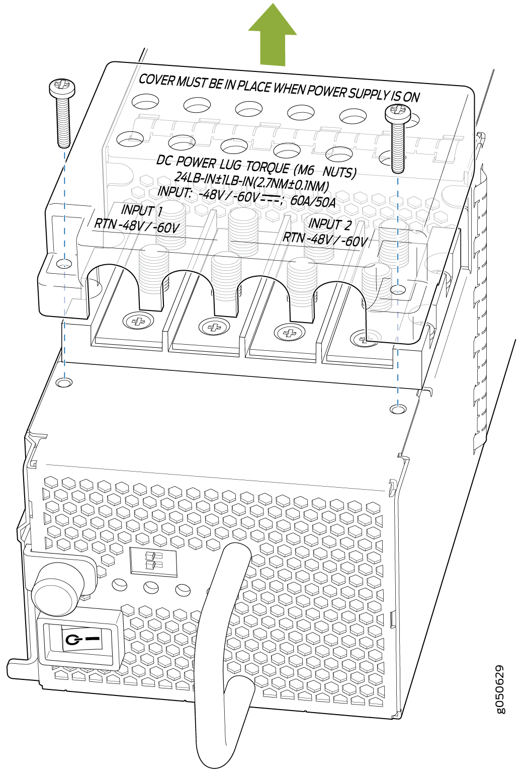
chassis, or wear heat-resistant gloves while removing the power supply. - Remove the plastic cable cover from the DC power input
terminals by using the Phillips (+) screwdriver, number 2,
to loosen the screws (see Figure 32).Figure 32: Removing the Plastic Cable Cover on a QFX10000-PWR-DC Power Supply
-
Install heat-shrink tubing insulation around the power cables.
To install heat-shrink tubing:
-
Slide the tubing over the portion of the cable where it is attached to the lug barrel. Ensure that tubing covers the end of the wire and the barrel of the lug attached to it.
-
Shrink the tubing with a heat gun. Ensure that you heat all sides of the tubing evenly so that it shrinks around the cable tightly.
Figure 33 shows the steps to install heat-shrink tubing.
Note:Do not overheat the tubing.
Figure 33: How to Install Heat-Shrink Tubing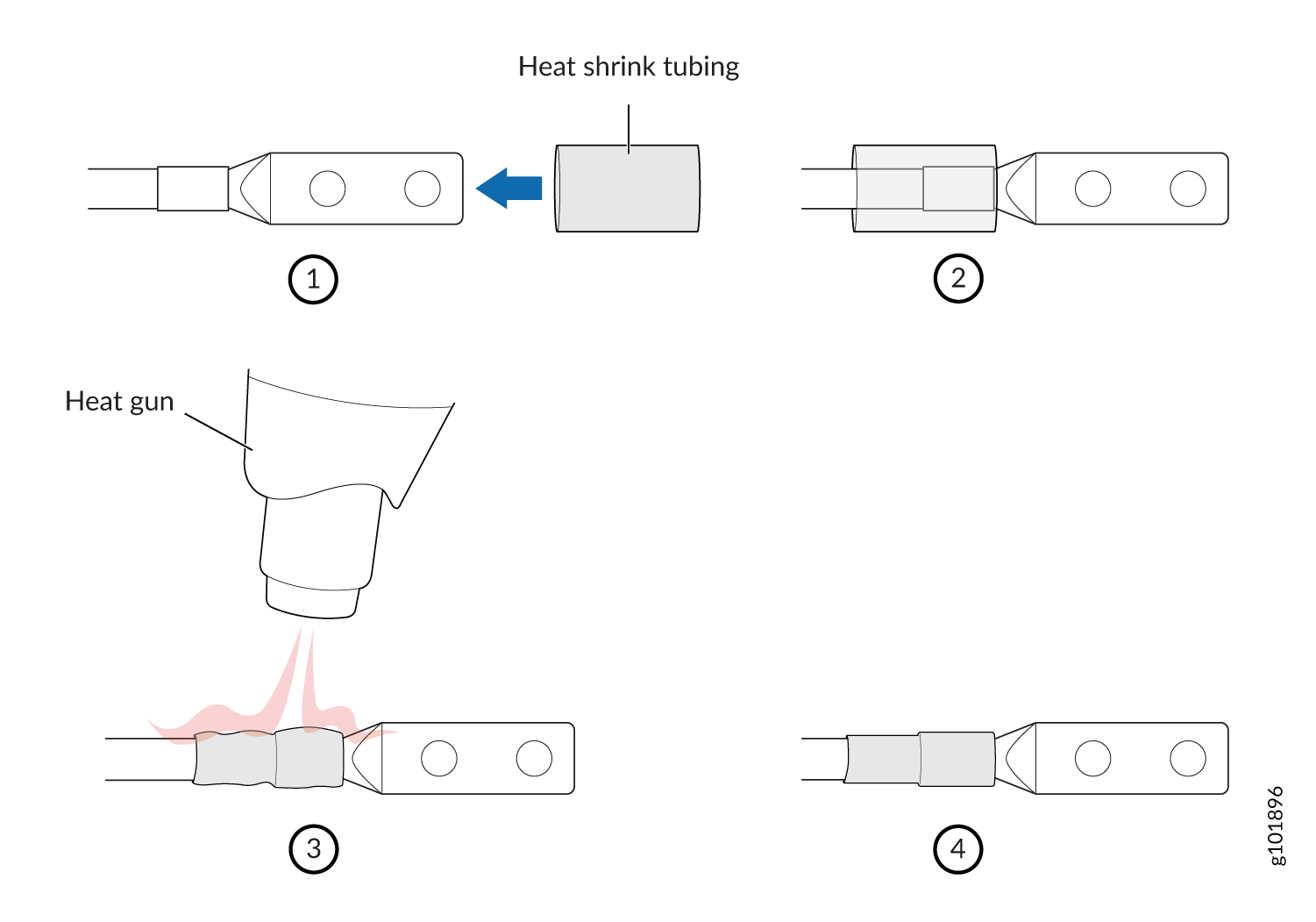
-
-
Install each power cable lug on the DC power input terminal, securing it with
the nut (see Figure 34). Apply between 23 in.-lb (2.6 Nm) and 25 in.-lb (2.8 Nm) of torque to each
nut. (Use the 13/32 in. [10 mm] nut driver or socket wrench.)
-
Secure each positive (+) DC source power cable lug to the RTN (return) DC power input terminal.
-
Secure each negative (–) DC source power cable lug to the –48V (input) DC power input terminal.
Figure 34: Connecting the QFX10000-PWR-DC Power Supply Cables to a QFX10000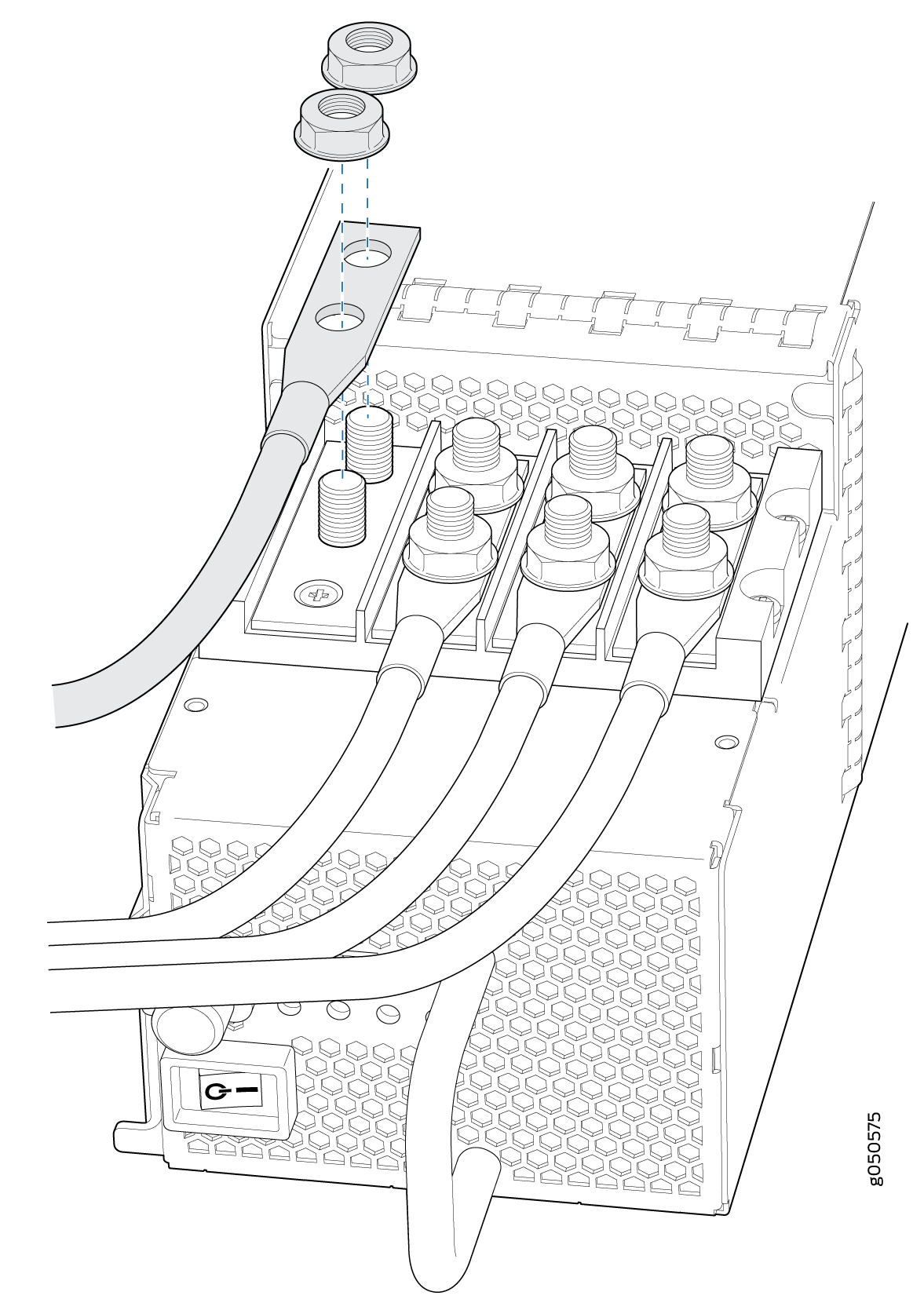
Each power supply has two independent sets of DC power input terminals (INPUT 1: RTN –48V/–60V: and INPUT 2: : RTN –48V/–60V). For feed redundancy, each power supply must be powered by dedicated power feeds derived from feed INPUT 1 and feed INPUT 2. This configuration provides the commonly deployed INPUT 1 / INPUT 2 feed redundancy for the switch. There is basic insulation between the inputs and the chassis ground. Also, there is basic insulation between RTN input feeds.
-
- If the power supply slot on the chassis has a cover panel
on it, insert your thumb and forefinger into the finger holes, squeeze,
and pull the cover panel out of the slot. Save the cover panel for
later use (see Figure 35 for
QFX10008 installations and Figure 36 for QFX10016 installations).Figure 35: Removing the PSU Cover Panel on a QFX10008Figure 36: Removing the PSU Cover Panel on a QFX10016
-
Tighten the captive screw by turning it clockwise by using your fingers or by
using the Phillips (+) screwdriver, number 1. Do not overtighten—do not apply
more than 7.3 lb-in. (0.82 Nm) of torque to the screws. When the screw is
completely tight, the latch locks into the switch chassis.
Figure 37: Installing a QFX10000-PWR-DC Power Supply in a QFX10008
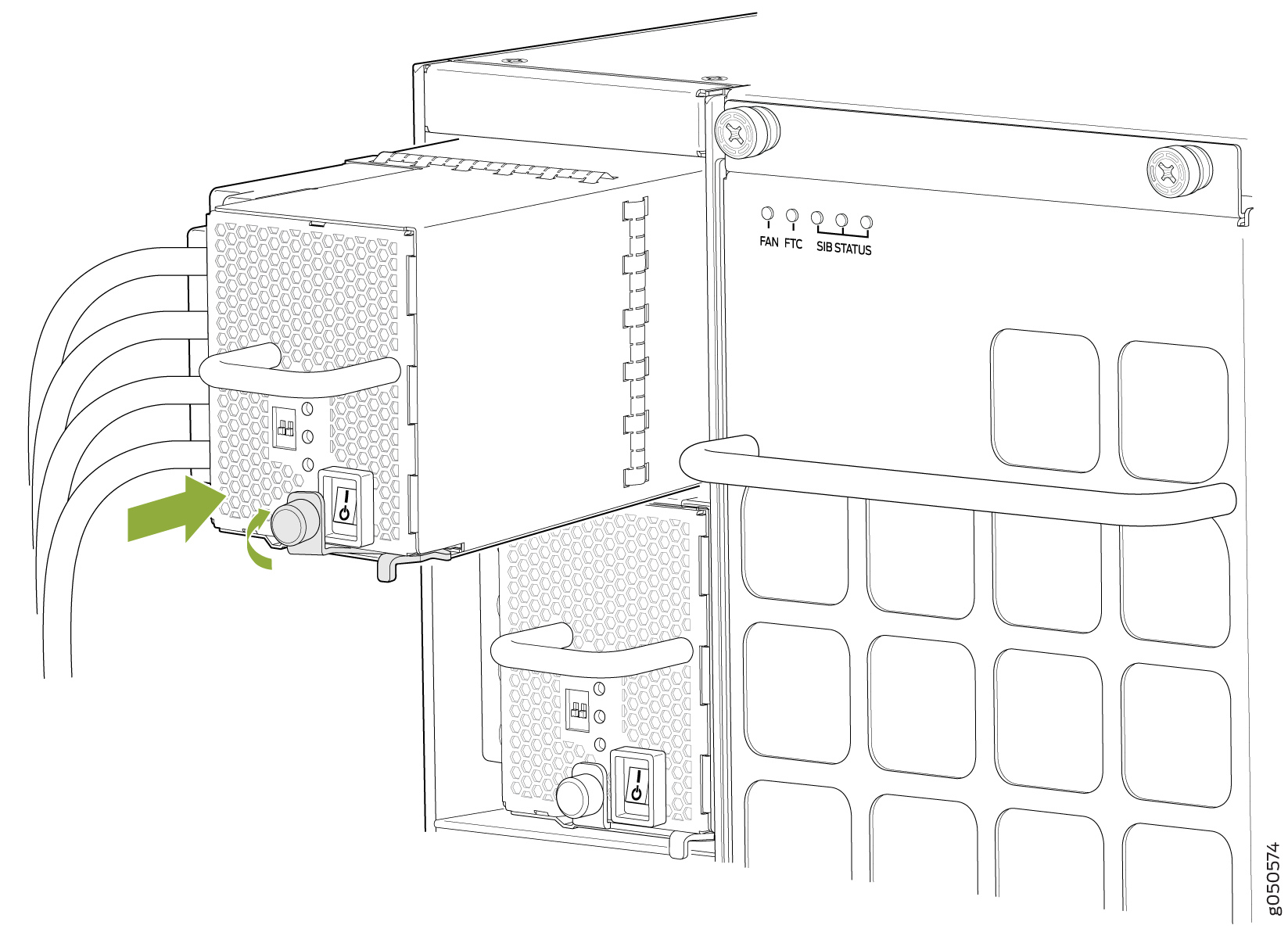 Figure 38: Installing a QFX10000-PWR-DC Power Supply in a QFX10016
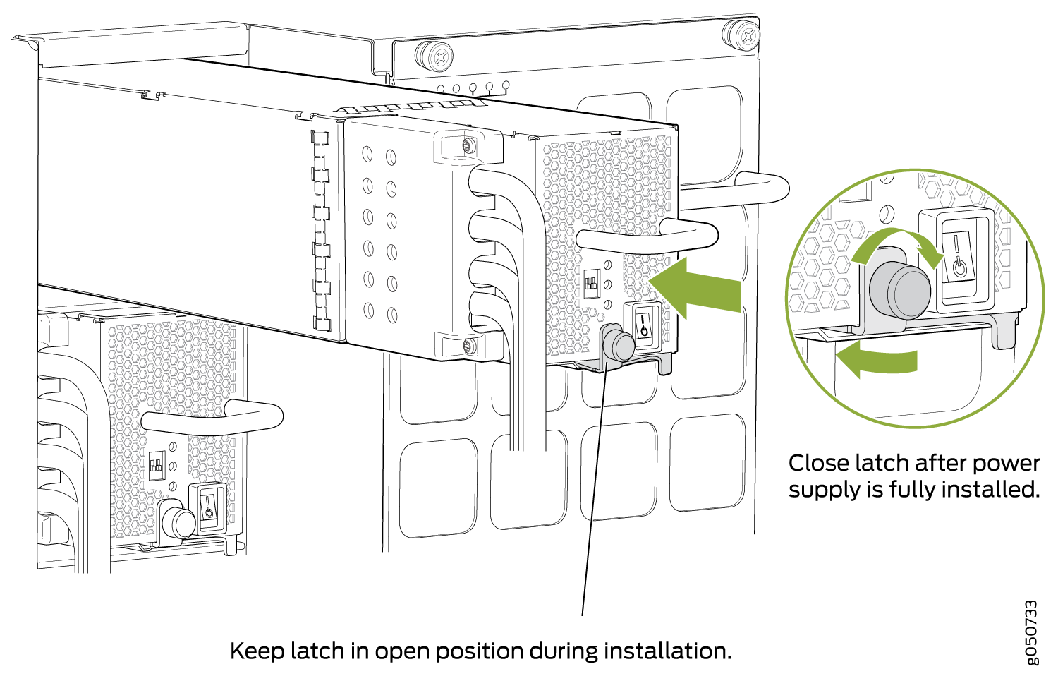 Note:
Note:Ensure that the ejector is fully open to avoid scratching the chassis.
- Route INP1 cables to a power source and INP2 to another
power source. The QFX10000-PWR-DC shares power, so if power dips on
one input, the power supply is able to load balance internally. See Figure 39 and Figure 40.Figure 39: Proper Load Balancing for QFX10000-PWR-DC Power Cables on QFX10008
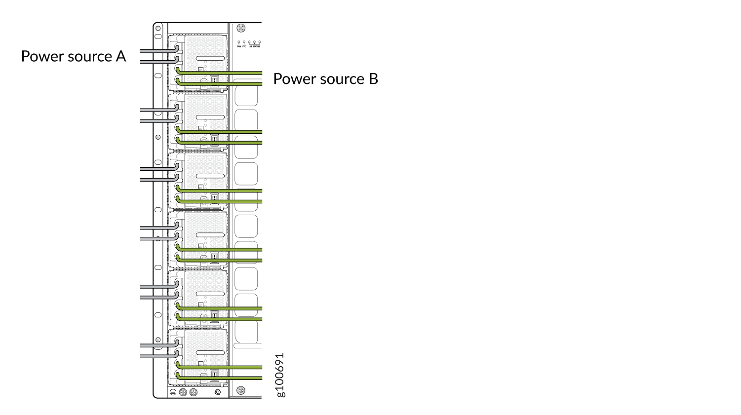 Figure 40: Proper Load Balancing for QFX10000-PWR-DC Power Cables on QFX100016
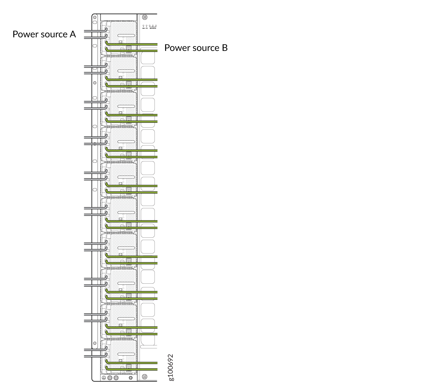 Warning:
Ensure that the power cables do not block access to router components or drape where people can trip on them. Always prevent cables from being exposed to hot air exhaust by routing them away from the fan trays and power supplies at the rear of the chassis.
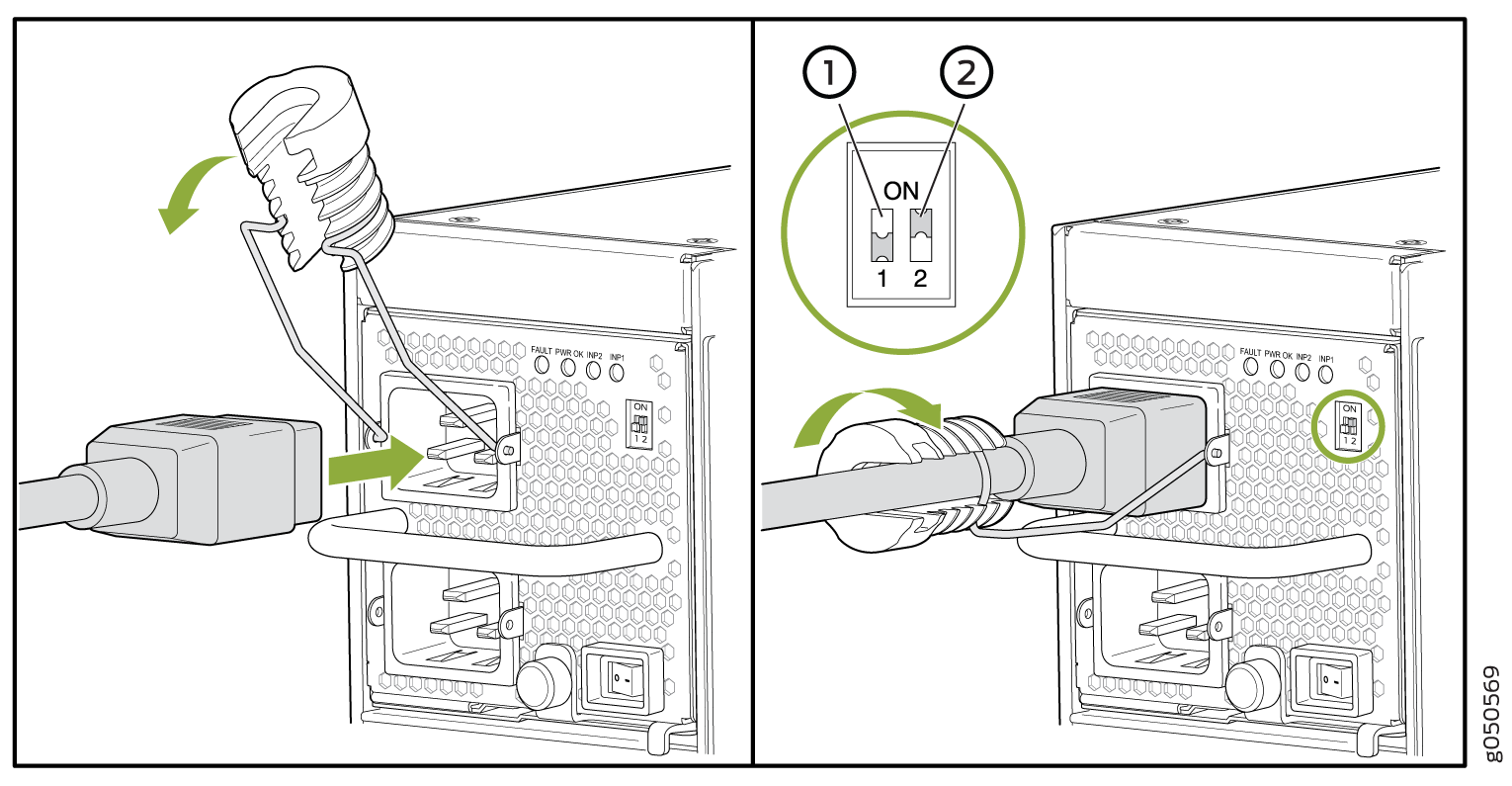
- Set the enable switches for input 1 and input 2 (see Figure 41).
Set both enable switches to the | (on) position when using both source inputs. When not using source redundancy, set the unused source to the O (off) position. The LED turns red and indicates an error if a source input is not in use and the enable switch is | (on).
Figure 41: Setting the Enable Switches for the Power Source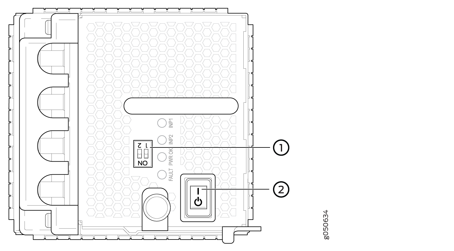 1—
1—Dip switches for enabling input sources
2—Power switch, on (|) and standby (o)
How to Remove a JNP10K-PWR-DC2 Power Supply
Before you remove a DC power supply from the switch:
Ensure you understand how to prevent ESD damage. See Prevention of Electrostatic Discharge Damage.
Ensure that you have the following parts and tools available to remove a JNP10K-PWR-DC2 power supply:
Heat protective gloves able to withstand temperatures in the range of 158°F (70°C) to 176°F (80°C)
Electrostatic discharge (ESD) grounding strap
Phillips (+) screwdriver, numbers 1 and 2
13/32 in. (10 mm) nut driver or socket wrench
Replacement power supply or a cover panel for the power supply slot
The JNP10K-PWR-DC2 power supply in a QFX10000 chassis is a hot-removable and hot-insertable field-replaceable unit (FRU). You remove power supplies from the rear of the chassis.
A working JNP10K-PWR-DC2 power supply can reach temperatures in the range of 158°F (70°C) to 176°F (80°C); In order to avoid injury, do not touch a running power supply with your bare hands.

Before you remove a power supply, ensure that you have power supplies sufficient to power the switch left in the chassis. See QFX10008 Power Planning, QFX10016 Power Planning and Power Requirements for QFX10000 Components.
Do not leave the power supply slot empty for a long time while the switch is operational. Either replace the power supply promptly or install a cover panel over the empty slot.
To remove a JNP10K-PWR-DC2 power supply from a QFX10000 switch:
- Attach the electrostatic discharge (ESD) grounding strap
to your bare wrist, and connect the strap to the ESD point on the
chassis. There is an ESD point located next to the protective earthing
terminal and below PSU 5 on the QFX10008
rear panel (see Figure 42 and below PSU_9 on the QFX10016 (see Figure 43).Figure 42: ESD Point on QFX10008 Chassis Rear1—
ESD point
Figure 43: ESD Point on QFX10016 Chassis Rear1—ESD point
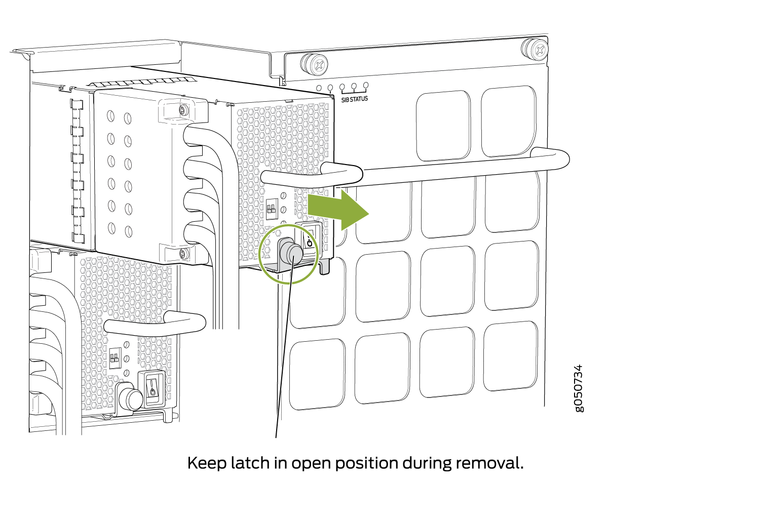
- Rotate the captive screw away from the faceplate of the
power supply to release the latch. (See Figure 44 and Figure 45.)Figure 44: Removing a JNP10K-PWR-DC2 Power Supply on QFX10008
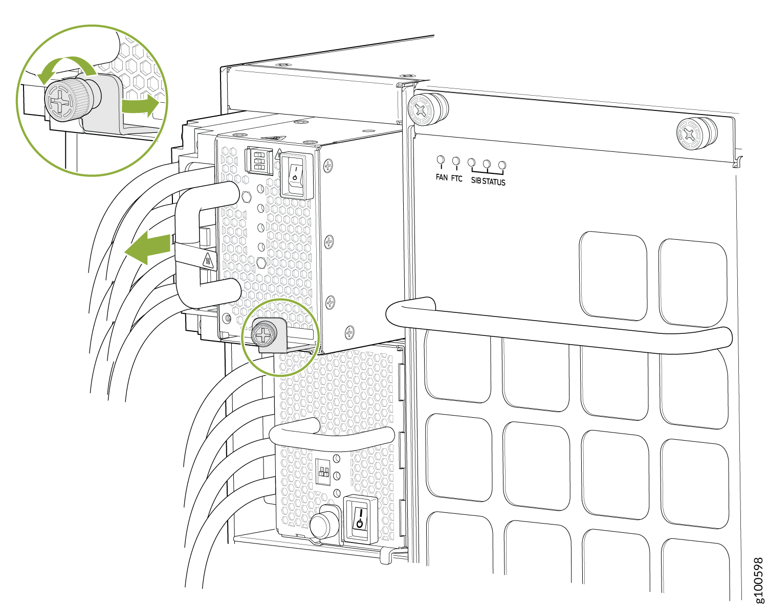 Figure 45: Removing a JNP10K-PWR-DC2 Power Supply on QFX10016
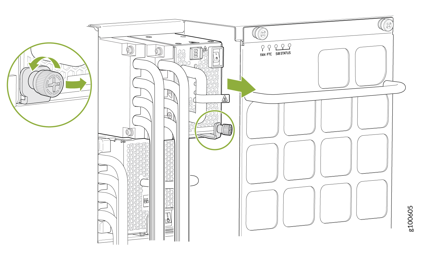
How to Install a JNP10K-PWR-DC2 Power Supply
Before you install an HVDC power supply in the chassis, ensure that you have followed all safety warnings and cautions:
Before performing DC power procedures, ensure that power is removed from the DC circuit. To ensure that all power is off, locate the circuit breaker on the panel board that services the DC circuit, switch the circuit breaker to the OFF position, and tape the switch handle of the circuit breaker in the OFF position.
Protect yourself from severe burns by wearing heat-protective gloves when removing a working HVDC power supply from the chassis. HVDC power supplies can reach in the range of 158°F (70°C) to 176°F (80°C).
Before you connect power to the switch, a licensed electrician must attach a cable lug to the grounding and power cables that you supply. A cable with an incorrectly attached lug can damage the switch (for example, by causing a short circuit).
Do not mix AC, DC, or HVDC power supplies in the same running chassis. You can mix DC and HVDC power supplies while swapping out one type for another during installation.
To meet safety and electromagnetic interference (EMI) requirements and to ensure proper operation, you must connect QFX10008 switches to earth ground before you connect them to power. For installations that require a separate grounding conductor to the chassis, use the protective earthing terminal on the switch chassis to connect to earth ground. For instructions on connecting a QFX10000 switch to ground using a separate grounding conductor, see Connect the QFX10008 or QFX10016 to Earth Ground.
The battery returns of the JNP10K-PWR-DC2 power supply must be connected as an isolated DC return (DC-I).
Ensure you understand how to prevent ESD damage. See Prevention of Electrostatic Discharge Damage.
Ensure that you have the following parts and tools available to install a DC power supply:
Electrostatic discharge (ESD) grounding strap
Use high current cable assembly, CBL-PWR2-BARE (not provided) with the cable lugs (provided) attached
The provided terminal lugs for the JNP10K-PWR-DC2 are Panduit LCD4-14A-L, or equivalent, and sized for 4 AWG (21.1 mm2) power source cables. We recommend that you install heat-shrink tubing insulation around the crimped section of the power cables and lugs.
13/32 in. (10 mm) nut driver or socket wrench
Phillips (+) screwdrivers, numbers 1 and 2
Multimeter
The JNP10K-PWR-DC2 power supply in a QFX10000 chassis is a hot-removable and hot-insertable field-replaceable unit (FRU). You can install up to 6 power supplies in a QFX10008 switch chassis. All HVDC power supplies install in the rear of the chassis in the slots along the left side of the chassis.
To install a JNP10K-PWR-DC2 power supply in a QFX10008 or QFX10016 :
- Attach the electrostatic discharge (ESD) grounding strap
to your bare wrist, and connect the strap to the ESD point on the
chassis. There is an ESD point located next to the protective earthing
terminal and below PSU 5 on the QFX10008
rear panel (see Figure 46) and below PSU_9 on the QFX10016 (see Figure 47).Figure 46: ESD Point on QFX10008 Chassis Rear1—
ESD point
Figure 47: ESD Point on QFX10016 Chassis Rear1—ESD point
- Remove the plastic cable cover from the power input terminals
by using the Phillips (+) screwdriver, number 2, to
loosen the screws (see Figure 48).Figure 48: Removing the Plastic Cable Cover on a JNP10K-PWR-DC2 Power Supply
-
Install heat-shrink tubing insulation around the power cables.
To install heat-shrink tubing:
-
Slide the tubing over the portion of the cable where it is attached to the lug barrel. Ensure that tubing covers the end of the wire and the barrel of the lug attached to it.
-
Shrink the tubing with a heat gun. Ensure that you heat all sides of the tubing evenly so that it shrinks around the cable tightly.
Figure 49 shows the steps to install heat-shrink tubing.
Note:Do not overheat the tubing.
Figure 49: How to Install Heat-Shrink Tubing
-
-
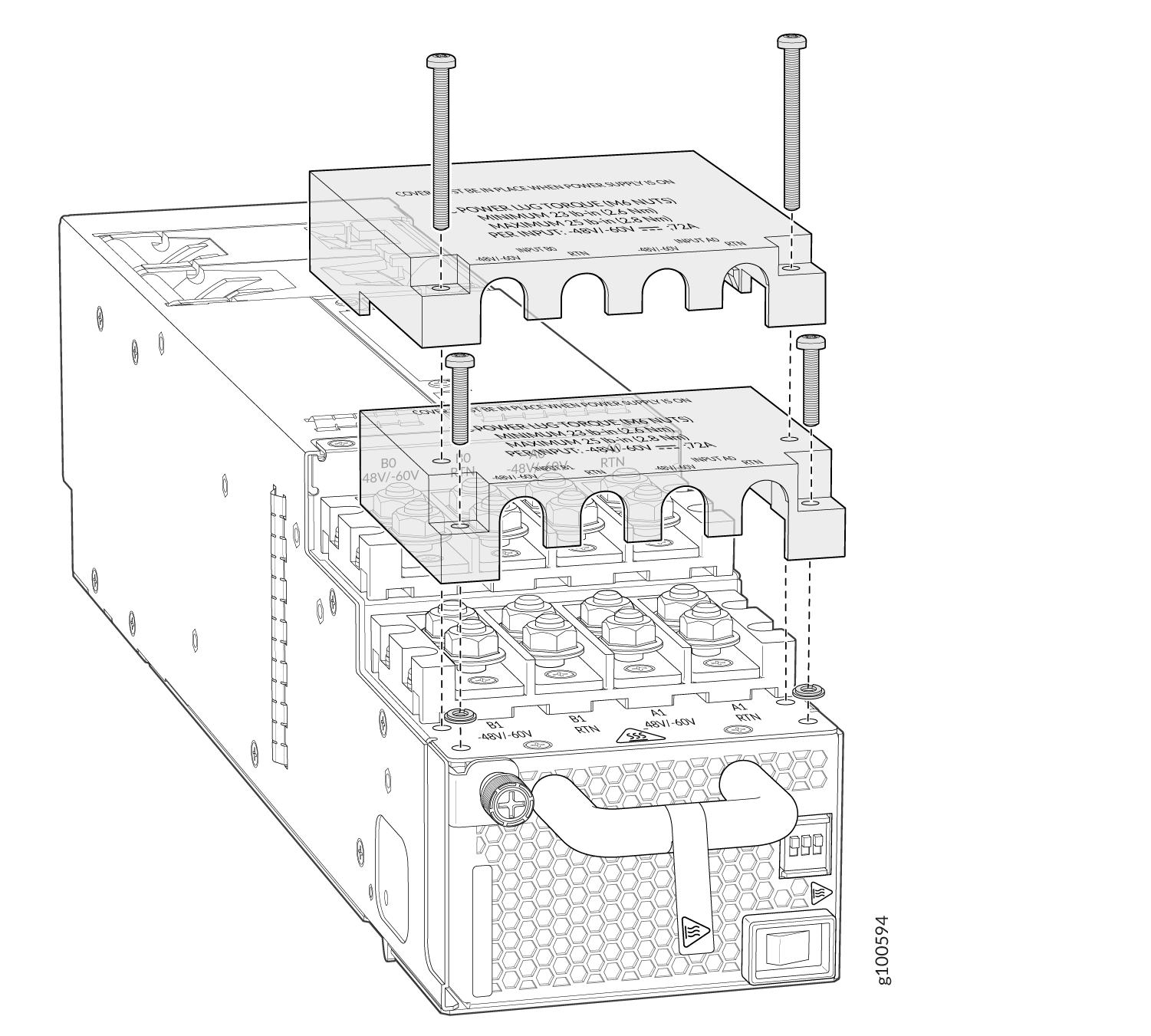
Install each power cable lug on the DC power input terminal, securing it
with the nut (see Figure 50). Apply between 23 in.-lb (2.6 N-m) and 25 in.-lb (2.8 N-m) of torque to
each nut. (Use the 13/32 in. [10 mm] nut driver or socket wrench.)
-
Secure each positive (+) DC source power cable lug to the RTN (return) DC power input terminal.
-
Secure each negative (–) DC source power cable lug to the –48V (input) DC power input terminal.
Each power supply has two independent sets of DC power input terminals (INPUT 1: RTN –48V/–60V: and INPUT 2: : RTN –48V/–60V). For feed redundancy, each power supply must be powered by dedicated power feeds derived from feed INPUT 1 and feed INPUT 2. This configuration provides the commonly deployed INPUT 1 / INPUT 2 feed redundancy for the switch. There is basic insulation between the inputs and the chassis ground. Also, there is basic insulation between RTN input feeds.
Figure 50: Connecting the DC Power Supply Cables to a JNP10K-PWR-DC2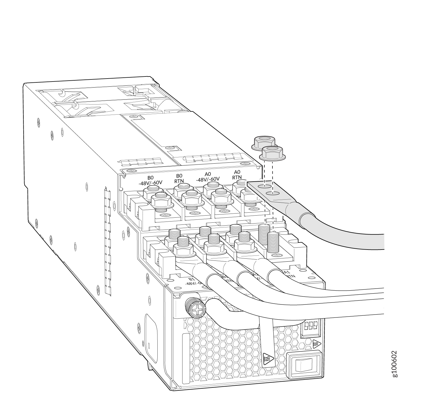
-
- If the power supply slot on the chassis has a cover panel
on it, insert your thumb and forefinger into the finger holes, squeeze,
and pull the cover out of the slot. Save the cover panel for later
use (see Figure 51 and Figure 52).Figure 51: Removing the Power Supply Cover Panel on a QFX10008Figure 52: Removing the Power Supply Cover Panel on a QFX10016
-
Tighten the captive screw by turning it clockwise by using your fingers or
by using the Phillips (+) screwdriver, number 1. Do not overtighten—do not
apply more than 7.3 lb-in (0.82 Nm) of torque to the screws. When the screw
is completely tight, the latch locks into the switch chassis.
Figure 53: Installing a JNP10K-PWR-DC2 in QFX10008
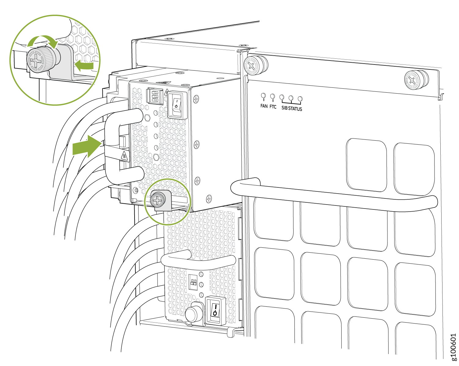 Figure 54: Installing a JNP10K-PWR-DC2 in QFX10016
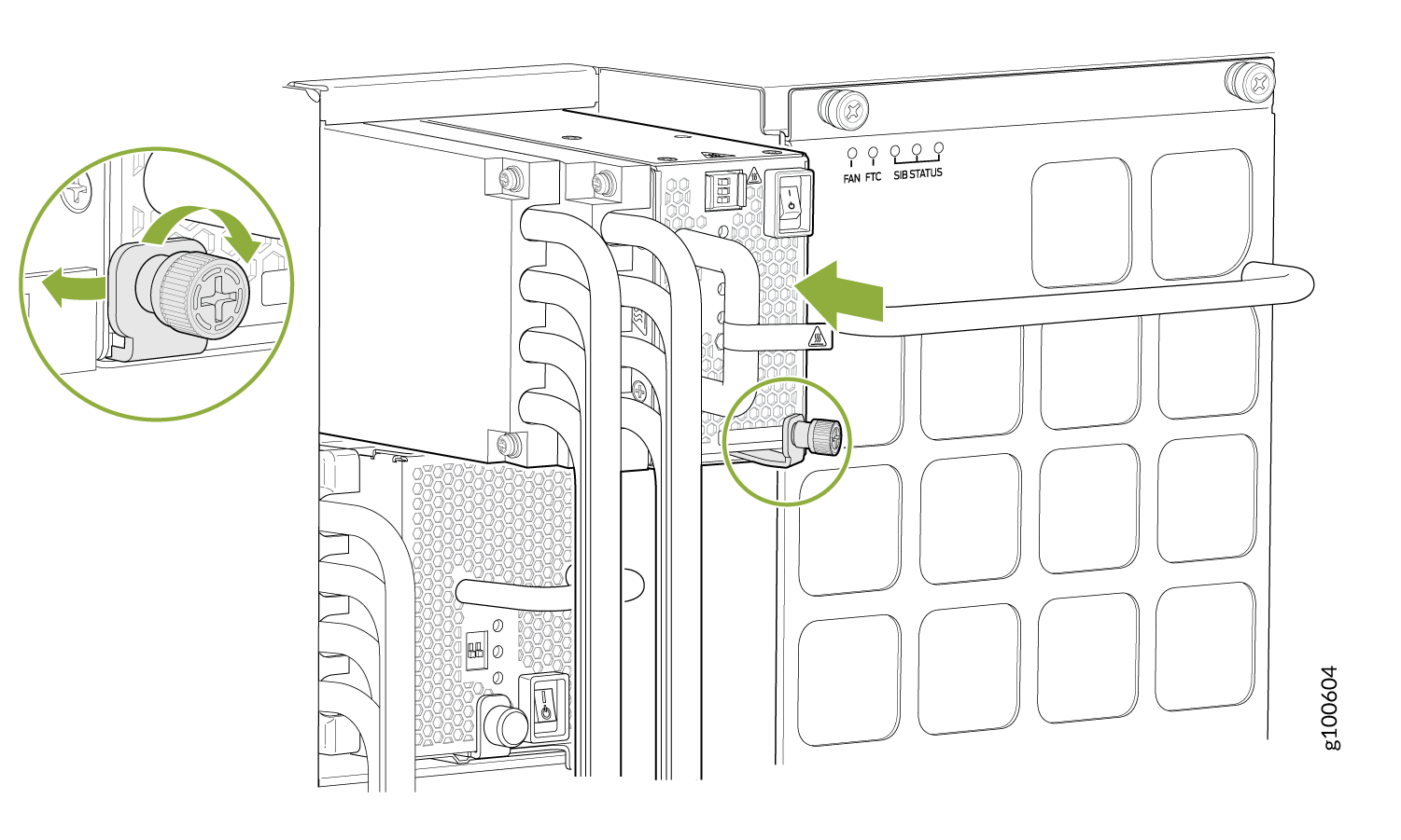
- Route INP1 cables to a power source and INP2 to another
power source. The JNP10K-PWR-DC2 shares power, so if power dips on
one input, the power supply is able to load balance internally. See Figure 55 and Figure 56.Figure 55: Proper Load Balancing for JNP10K-PWR-DC2 Power Cables on QFX10008
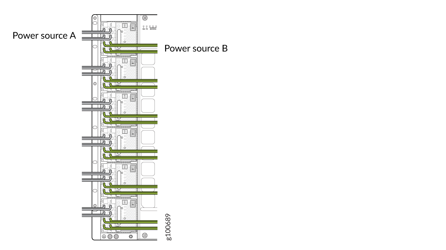 Figure 56: Proper Load Balancing for JNP10K-PWR-DC2 Power Cables on QFX100016
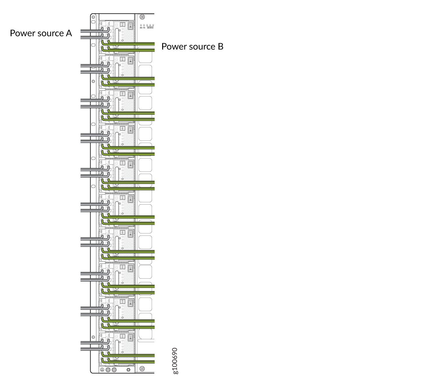 Warning:
Ensure that the power cables do not block access to router components or drape where people can trip on them. Always prevent cables from being exposed to hot air exhaust by routing them away from the fan trays and power supplies at the rear of the chassis.
- Set the three DIP switches to set the inputs and whether
the power supply is running at 3000 W or at 5500 W. See Table 2 and Figure 57.
Set both enable switches to the on position when using both source inputs. When not using source redundancy, set the unused source to the O (off) position. The LED turns red and indicates an error if a source input is not in use and the enable switch is | (on).
Table 2: Setting the JNP10K-PWR-DC2 DIP Switches Switch
State
Field
1
On
IP0 is present
Off
IP0 is not present
2
On
IP1 is present
Off
IP1 is not present
3
On
Enabled for 30 A feed; 5500-W for a single feed, 5000-W for dual feeds
Off
Enabled for 20 A feed; power supply capacity is 3000-W
Figure 57: Setting the Enable Switches for the Power Source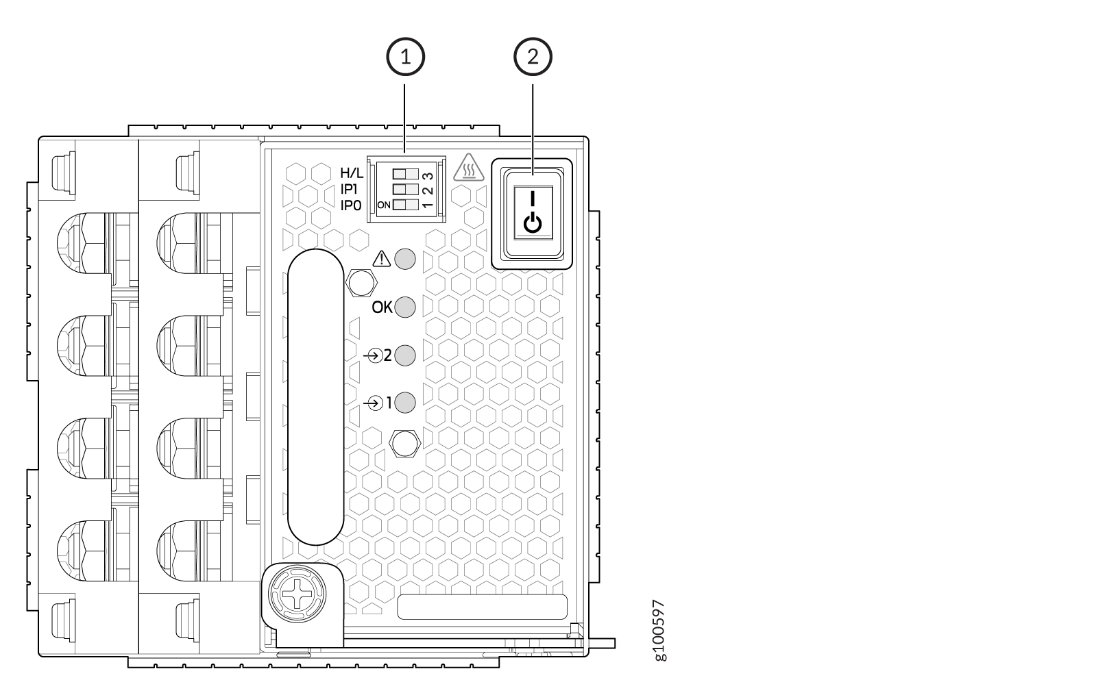 1—
1—Dip switches
2—Power switch, on (|) and standby (O)