QFX10000 Routing and Control Board
QFX10000 Routing and Control Board Description
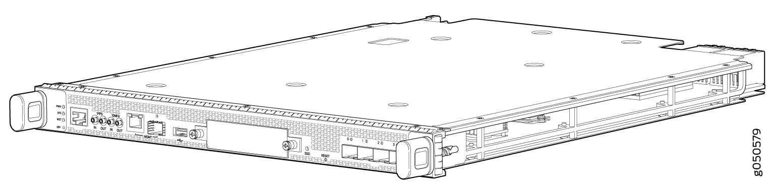
The Routing and Control Board (RCB) is responsible for system management in a QFX10008 or QFX10016 (see Figure 1). The switch chassis can run with one or two RCBs. The base configurations ship with one RCB that can be expanded with a second RCB for a fully-redundant system. When two RCBs are installed, one functions as the primary and the second as a backup. If the primary RCB is removed, the backup restarts and becomes the primary.
This topic covers:
RCB Functions
The RCB integrates the control plane and Routing Engine functions into a single management unit. Each RCB provides all the functions needed to manage the operation of the modular chassis:
System control functions such as environmental monitoring
Routing Layer 2 and Layer 3 protocols
Communication to all components such as line cards, Switch Interface Boards (SIBs), and power and cooling
Transparent clocking
Alarm and logging functions
RCB Components
Each RCB consists of the following internal components:
Quad-core 2.5 GHz CPU
32 GB SDRAM
50 GB or 100 GB onboard SATA SSD
Other standard interfaces are shown in Figure 2.
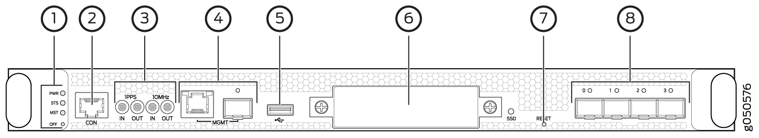
1 — RCB status LEDs | 5 — USB 2.0 port |
2 — Console port | 6 — SATA SSD slot |
3 — PTP-capable connections: SMB In, SMB Out, 10 MHz In, 10 MHz Out | 7 — Reset button |
4 — Ethernet management ports: RJ-45 for 10/100/1000 BASE-T (em0) and small-form factor pluggable (SFP) for fiber (em1). If both copper and fiber cables are installed, the RJ-45 is the default. | 8 — Four SFP+ ports (reserved for future use) |
You can use either management interface, em0 or em1 when the RCB is running as the primary RE. Use only em1 when the RCB is running as the backup RE.
QFX10000 Routing and Control Board LEDs
The QFX10000 Routing and Control Boards (RCBs) have four types of LED indicators (see Figure 3).
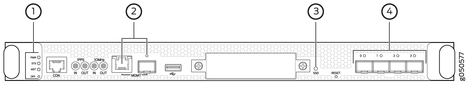
1 — RCB status panel | 3 — SATA SSD |
2 — Management ports | 4 — Virtual port connection |
RCB Status Panel LEDs
The RCB status panel LEDs indicate the state of the RCB (see Figure 4).
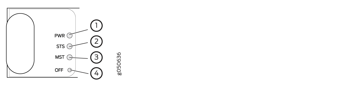
1 — Power (PWR) LED | 3 — Primary (MST) LED |
2 — Status (STS) LED | 4 — Offline button |
Table 1 describes the LEDs on the RCB status panel.
LED |
Color |
State |
Description |
|---|---|---|---|
PWR |
Green |
On steadily |
The RCB is receiving adequate power. |
Yellow |
Blinking |
The RCB has detected an error. |
|
Dark |
Unlit |
The RCB is not powered up. |
|
STS |
Green |
On steadily |
The RCB is online and functioning correctly. |
Green |
Blinking |
The beacon feature is enabled. |
|
Yellow |
On steadily |
The RCB is booting. |
|
Yellow |
Blinking |
The RCB has detected an error. |
|
Dark |
Unlit |
The power supply is switched off. |
|
MST |
Green |
On steadily |
The RCB is the primary. |
Dark |
Unlit |
The RCB is the backup. |
QFX10000 Management Port LEDs
There are two management ports on the RCB of a QFX10008 and QFX10016 that have LEDs that indicate link status and link activity. These two ports, located on the RCB panel between the clocking connections and the USB port, are both labeled MGMT. The left management port is an SFP cage that can accommodate up to 1G copper or fiber connections (see Figure 5). The copper (RJ-45) port has separate LEDs for status and activity. The fiber (SFP) port has a combination link and activity LED.
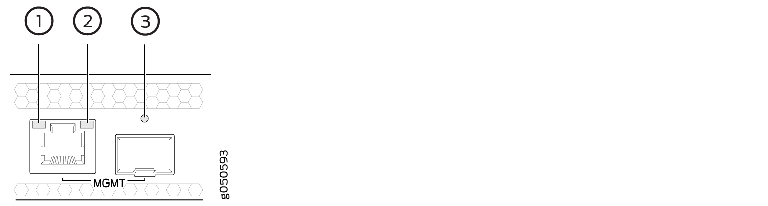
1 — Status LED (RJ-45) | 3 — Link LED–Green indicates the link is up; blinking indicates activity (SFP) |
2 — Activity LED (RJ-45) |
Table 2 describes the RJ-45 management port LEDs, and Table 3 describes the SFP status LEDs.
LED |
Color |
State |
Description |
|---|---|---|---|
Port speed |
Unlit |
Off |
The port speed is 10 MB. |
Green |
Blinking |
The port speed is 100 MB. |
|
Green |
On steadily |
The port speed is 1000 MB. |
|
Link/Activity/Status |
Unlit |
Off |
No link is established, there is a fault, or the link is down. |
Green |
On steadily |
A link is established. |
|
Blinking |
There is link activity. |
||
Yellow |
Blinking or flickering |
The beacon feature is enabled. |
LED |
Color |
State |
Description |
|---|---|---|---|
Link/Activity/Status |
Unlit |
Off |
No transceiver is present. |
Green |
On steadily |
A link is established. The interface is up. |
|
Green |
Blinking or flickering |
The beacon feature is enabled. |
|
Yellow |
Blinking |
An error has occurred. |
SATA SSD LEDs
The Serial Advanced Technology Attachment (SATA) solid-state drive (SSD) LEDs indicate the status of the optional drive.
Table 4 describes the LEDs for the optional SATA drive.
LED |
Color |
State |
Description |
|---|---|---|---|
SSD |
Green |
On steadily |
A SATA drive is present. |
Green |
Blinking |
The drive is active. |
|
Yellow |
On steadily |
The drive is active. |
|
Dark |
Unlit |
A drive is not installed. |
Virtual Port Connections
The four small form-factor pluggable plus (SFP+) ports are reserved for future use.