QFX10000 DC Power System
The QFX10000 supports three types of DC power supply modules:
QFX10000-PWR-DC—A 2500-W, 12-VDC dual power supply.
JNP10K-PWR-DC2—A 5500-W, 12-VDC quad input power supply. For details on this power supply, see JNP10K-PWR-DC2 Power Supply.
JNP10K-PWR-AC2—An AC, high-voltage alternating current (HVAC,) or high-voltage direct current (HVDC) power supply. In high power mode, this power supply provides 12.3 V, 5000 W with a single feed and 5500 W with dual feeds. For details on this power supply, see JNP10K-PWR-AC2 Power Supply.
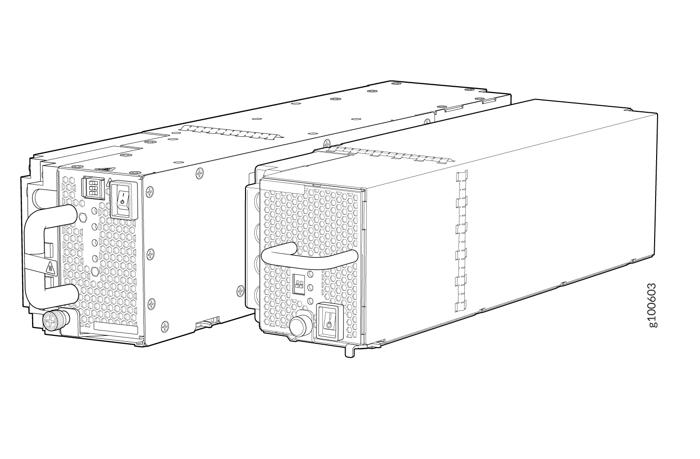
All three power supplies fit into a power slot bay, but the JNP10K-PWR-AC2 and JNP10K-PWR-DC2 are longer and protrude from the bay when fully inserted into the chassis. See Figure 1.
QFX10000-PWR-DC Power Supply
Do not mix power supply models in the same chassis in a running environment. DC and HVDC can coexist in the same chassis during the hot swap of DC for HVDC.
The QFX10000-PWR-DC power supply is a 2500-W, 12-VDC, dual input power supply. The output of each QFX10000-PWR-DC power supply is 12-VDC. The output power is 2500 W.
The switch is pluggable type A equipment installed in a restricted-access location. It has a separate protective earthing terminal on the chassis that must be connected to earth ground permanently to ground the chassis adequately and protect the operator from electrical hazards.
Before you begin installing the switch, ensure that a licensed electrician has attached an appropriate grounding lug to the grounding cable that you supply. Using a grounding cable with an incorrectly attached lug can damage the switch.
QFX10000-PWR-DC power supplies are shipped only in the redundant configuration of QFX10000 switches. For details about different chassis configurations, see QFX10008 Configurations and Upgrade Options and QFX10016 Components and Configurations.
Each QFX10000-PWR-DC power supply weighs approximately 6 lb (2.7 kg) and has two independent pairs of DC input lugs (Input 1, RTN, –48V/–60V and Input 2, RTN, –48V/–60V) on the faceplate of the power supply. Each inlet requires a dedicated DC power feed. Although each inlet provides sufficient input power to provide full output, always connect to a dedicated DC power feed to provide redundancy. Only one power feed is operational at a time.
DC power models employ electronic A-B input selection. It provides 2n source redundancy and n+1 power supply redundancy using fewer power supplies than you would require in a 2n configuration. Should one power source fail, electronic A-B input selection switches the power supply to the alternate source.
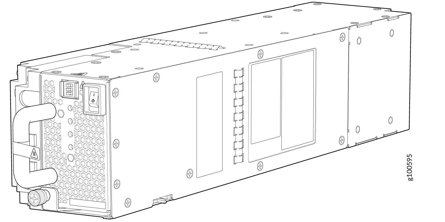
Each QFX10000-PWR-DC power supply has a power switch with international markings for on (|) and off (O), a fan, and four LEDs on the faceplate that indicate the status of the power supply. See Figure 2.
The QFX10000-PWR-DC power supply requires a dedicated circuit breaker for each input DC feed. The chosen breaker should be sized to deliver 60 A of input current.
Each power supply connects to the combined power rail in a QFX10008 or QFX10016. The power rail distributes the output power produced by the power supplies to different switch components. Each QFX10000-PWR-DC power supply provides power to all the components in the switch.
Ensure that the power cables do not block access to router components or drape where people can trip on them. Always prevent cables from being exposed to hot air exhaust by routing them away from the fan trays and power supplies at the rear of the chassis.
A DC power supply can operate with only one input DC feed connected. The RCB only enables the components for which sufficient power is available.
The JNP10K-PWR-DC power supplies do not share power.
QFX10000-PWR-DC power supplies can use the standard bus or the enhanced bus.
Each QFX10000-PWR-DC power supply has its own fan and is cooled by its own internal cooling system. The airflow is from the front of the power supply to the back. Hot air exhausts from the rear of the chassis.
QFX10000-PWR-DC Power Specifications
QFX10000-PWR-DC power supplies are supported in only the QFX10008 and QFX10016 redundant configuration. Table 1 lists the power specifications for the QFX10000-PWR-DC power supply used in a QFX10000 modular chassis.
Item |
Specifications |
|---|---|
DC input voltage |
|
DC input current rating |
60 A maximum at nominal operating voltage (–48 VDC) for each input terminal |
Output power |
2500 W |
Table 2 shows the physical specifications for a QFX10000-PWR-DC power supply.
Specification |
Value |
|---|---|
Height |
3.5 in. (8.89 cm) |
Width |
3.6 in. (9.14 cm) |
Depth |
14.4 in. (36.58 cm) |
Weight |
6 lb (2.72 kg) |
JNP10K-PWR-DC2 Power Supply
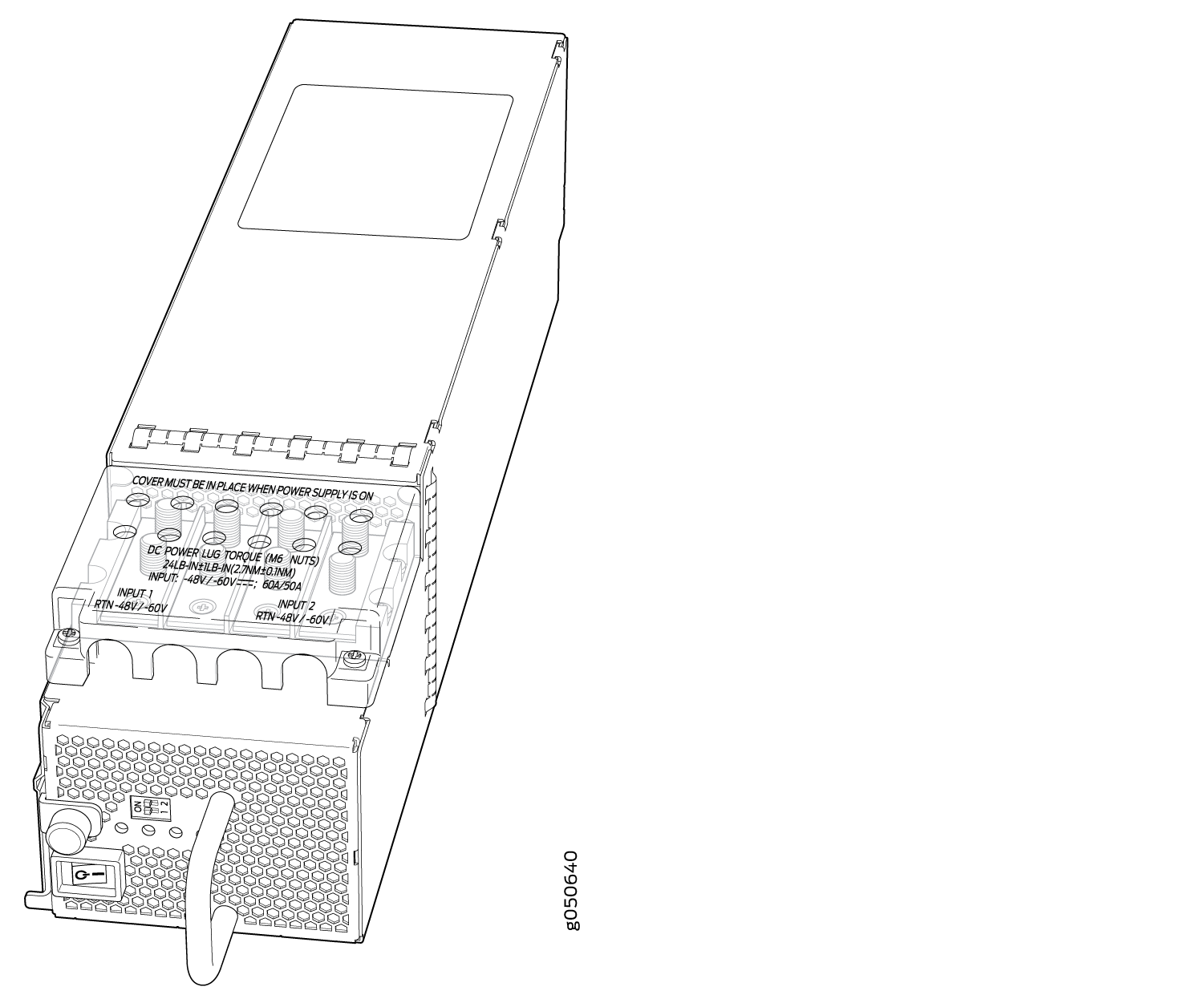
The JNP10K-PWR-DC2 power supply provides two power supplies in a single housing that accepts either 60 A or 80 A using four redundant input power feeds. PS_0 and PS_1 each have redundant input feeds: A0 and/or B0 for PS_0 and A1 and/or B1 for PS_1. The input is configured using a set of DIP switches on the power supply faceplate. The output is dependant on the settings of these DIP switches. See Table 3. See Figure 3.
The JNP10K-PWR-DC2 power supplies share power.
INP0 (Switch 1) |
INP1 (Switch 2) |
H/L (High Input 80 A/Low Input 60A) |
Output Power |
|---|---|---|---|
On |
On |
On (80 A) |
5500 W |
On |
On |
Off (60 A) |
4400 W |
On |
Off |
On (80 A) |
2750 W |
Off |
On |
On (80 A) |
2750 W |
On |
Off |
Off (60 A) |
2200 W |
Off |
On |
Off (60 A) |
2200 W |
Do not mix power supply models in the same chassis in a running environment. JNP10K-PWR-DC and JNP10K-PWR-DC2 can coexist in the same chassis during power supply upgrades.
The router is pluggable type A equipment installed in a restricted-access location. It has a separate protective earthing terminal on the chassis that must be connected to earth ground permanently to ground the chassis adequately and protect the operator from electrical hazards.
Before you begin installing the router, ensure that a licensed electrician has attached an appropriate grounding lug to the grounding cable that you supply. Using a grounding cable with an incorrectly attached lug can damage the router.
DC power supplies are shipped only in the redundant configuration of QFX10000 switches. For details about different chassis configurations, see QFX10008 Configurations and Upgrade Options and QFX10016 Components and Configurations.
Chassis with the enhanced bus support the full 5500 W available from the JNP10K-PWR-DC2. Chassis with the standard bus provides 3000 W for power budget from the power management software. To determine whether your system has the standard power bus or the enhanced power bus, see QFX10000 Status Panel.
JNP10K-PWR-DC2 Power Specifications
Table 4 lists the power specifications for the JNP10K-PWR-DC2 power supply used in a QFX10000 chassis.
Item |
Specifications |
|---|---|
DC input voltage |
|
DC input current rating |
|
Output pow er |
2200 W for low input (60-A) single feed 4400 W for low input (60-A) dual feed 2750 W for high input (80-A) single feed 5500 W for high input (80-A) dual feed |
Table 5 shows the physical specifications for a JNP10K-PWR-DC2 power supply.
Specification |
Value |
|---|---|
Height |
3.5 in. (8.89 cm) |
Width |
3.6 in. (1.63 cm) |
Depth |
16.05 in. (40.77 cm) |
Weight |
8.1 lb (3.67 kg) |
QFX10000-PWR-DC Power Supply LEDs
A QFX10000-PWR-DC power supply has four LEDs on its faceplate: INP1, INP1, PWR OK, and FAULT. These LEDs display information about the status of the power supply. See Figure 4.
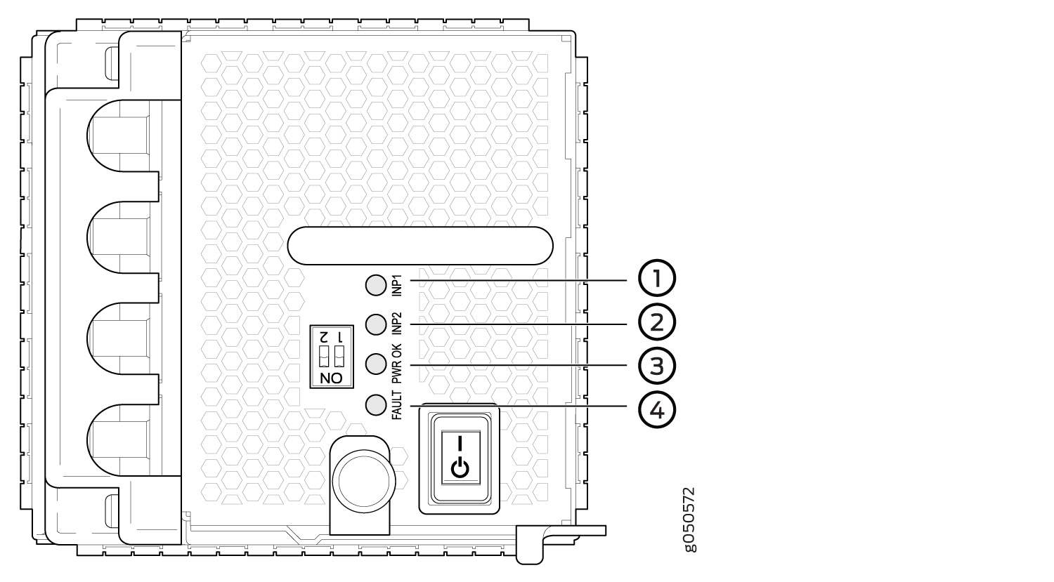
1 — INP1–Source input 1 | 3 — PWR OK |
2 — INP2–Source input 2 | 4 — FAULT |
Table 6 describes the LEDs in QFX10008 and QFX10016 modular chassis.
LED |
Color |
State |
Description |
|---|---|---|---|
1 (INP0 in CLI output) or 2 (INP1 in CLI output) |
Yellow |
Blinking |
Indicates the DC power input voltage is not within normal operating range. |
Green |
Solid |
DC power is within operating range (-40 VDC to -72 VDC). |
|
Unlit |
Off |
The power supply is switched off. |
|
PWR OK |
Green |
Solid |
DC power output is within normal operating range. |
Yellow |
Blinking |
The output is out of the limits. |
|
FAULT |
Red |
Solid |
Power supply has failed and must be replaced. |
Unlit |
Off |
Power supply is functioning normally. Or, only one input is powered and the enable switch for the input that is not powered is set to ON. See Connect DC Power to a QFX10008 or QFX10016 for more information on the enable switches. |
If the INP1 or INP2 and the PWR OK LED are unlit, the power cords are not installed properly or the power supply has failed.
If the INP1 or INP2 LED is lit green and the PWR OK LED is unlit, the power supply is not installed properly or the power supply has an internal failure.
If the FAULT LED is blinking, add a power supply to balance the power demand and supply.
JNP10K-PWR-DC2 Power Supply LEDs
A JNP10K-PWR-DC2 power supply module has four LEDs on its faceplate: 1, 2, OK, and the symbol for fault, !. These LEDs display information about the status of the power supply. See Figure 5.
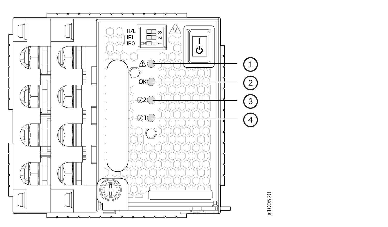
1 — !–FAULT | 3 — 2–Source input 1 |
2 — OK–Power okay | 4 — 1–Source input 0 |
Table 7 describes the LEDs on a JNP10K-PWR-DC2 power supply.
LED |
Color |
State |
Description |
|---|---|---|---|
1 (INP0 in CLI output) or 2 (INP1 in CLI output) |
Yellow |
Blinking |
Indicates the DC power input voltage is not within normal operating range. |
Green |
Solid |
DC power is within operating range (-40 VDC to -72 VDC). |
|
Unlit |
Off |
The power supply is switched off. |
|
OK |
Green |
Solid |
DC power output is within normal operating range. |
Yellow |
Blinking |
The output is out of the limits. |
|
! |
Red |
Solid |
Power supply has failed and must be replaced. |
Unlit |
Off |
Power supply is functioning normally. Or, only one input is powered and the enable switch for the input that is not powered is set to ON. See Connecting the QFX10008 or QFX10016 to Power for more information on the enable switches. |
If the 1 or 2 and the OK LED are unlit, the power cables are not installed properly or the power supply has failed.
If the 1 or LED is lit green and the OK LED is unlit, the power supply is not installed properly or the power supply has an internal failure.
If the ! LED is blinking, add a power supply to balance the power demand and supply.