ON THIS PAGE
Installing the PTX5000 in a Rack
Installing the PTX5000 Mounting Hardware for a Four-Post Rack or Cabinet
- Installing Cage Nuts, If Needed
- Installing the Four-Post Mounting Shelf and Rear Support Bracket
- Removing the Center-Mounting Brackets
Installing Cage Nuts, If Needed
Insert cage nuts, if needed, into the holes listed in Table 1 and Table 2 (an X indicates a mounting hole location). The hole distances are relative to the standard U division on the rack that is aligned with the bottom of the mounting shelf and rear support bracket.
To install cage nuts in a four-post rack:
- On the rear rack rails, insert cage nuts in the holes specified for the rear support bracket. Install the cage nuts in the rear of the rear rail (see Table 1).
- On the front rack rails, insert cage nuts in the holes specified for the four-post mounting shelf. Install the cage nuts in the front of the front rail (see Table 1).
- On the front rack rails, insert cage nuts in the holes specified for mounting the chassis. Install the cage nuts in the front of the front rail (see Table 2).
Hole |
Distance Above U Division |
Four-Post Rack Mounting Shelf |
Rear Support Bracket |
|
|---|---|---|---|---|
6 |
3.25 in. (8.3 cm) |
1.86 U |
X |
X |
5 |
2.63 in. (6.7 cm) |
1.5 U |
X |
X |
4 |
2.00 in. (5.1 cm) |
1.14 U |
X |
X |
3 |
1.50 in. (3.8 cm) |
0.86 U |
X |
X |
2 |
0.88 in. (2.2 cm) |
0.50 U |
X |
X |
1 |
0.25 in. (0.6 cm) |
0.14 U |
X |
X |
Hole |
Distance Above U Division |
|
|---|---|---|
110 |
63.88 in. (162.2 cm) |
36.50 U |
101 |
58.63 in. (148.9 cm) |
33.50 U |
92 |
53.38 in. (135.6 cm) |
30.50 U |
83 |
48.13 in. (122.2 cm) |
27.50 U |
74 |
42.88 in. (108.9 cm) |
24.50 U |
65 |
37.63 in. (95.6 cm) |
21.50 U |
56 |
32.38 in. (82.2 cm) |
18.50 U |
47 |
27.13 in. (68.9 cm) |
15.50 U |
38 |
21.88 in. (55.6 cm) |
12.50 U |
29 |
16.63 in. (42.2 cm) |
9.50 U |
20 |
11.38 in. (28.9 cm) |
6.50 U |
11 |
6.13 in. (15.6 cm) |
3.50 U |
The holes in the front-mounting flanges are spaced at 3 U (5.25 in. or 13.3 cm).
Installing the Four-Post Mounting Shelf and Rear Support Bracket
To install the four-post mounting shelf and rear support bracket (see Figure 1):
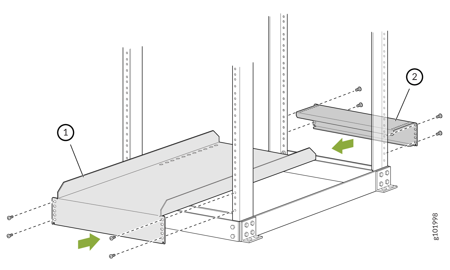
1 — Four-post mounting shelf | 2 — Rear support bracket |
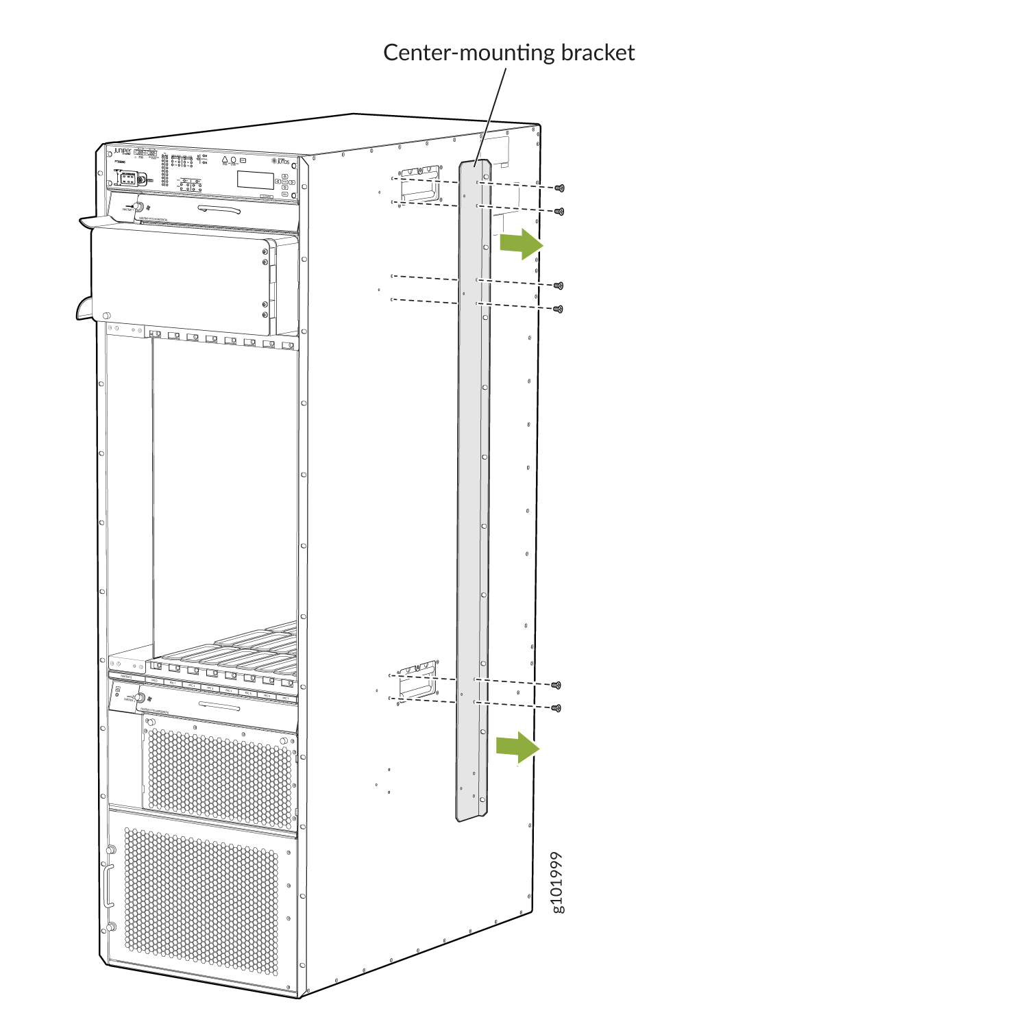
Removing the Center-Mounting Brackets
The center-mounting brackets are not used for a four-post rack, and must be removed from the chassis.
To remove the center-mounting brackets from the chassis:
- Loosen the screws from each bracket (see Figure 2).
- Remove each bracket.
Installing the PTX5000 Mounting Hardware for an Open-Frame Rack
Installing Cage Nuts, If Needed
Insert cage nuts, if needed, into the holes listed in Table 3 and Table 4. The hole distances are relative to the standard U division on the rack that is aligned with the bottom of the mounting shelf and rear support bracket.
To install cage nuts in an open-frame rack:
- On the rear side of both rack rails, insert cage nuts in the holes specified for the open-frame mounting shelf (see Table 3).
- On the front side of both rack rails, insert cage nuts in the holes specified for mounting the chassis (see Table 4).
Hole |
Distance Above U Division |
|
|---|---|---|
30 |
17.25 in. (43.8 cm) |
9.86 U |
27 |
15.5 in. (39.4 cm) |
8.86 U |
21 |
12.0 in. (30.5 cm) |
6.86 U |
15 |
8.5 in. (21.6 cm) |
4.86 U |
9 |
5.0 in. (12.7 cm) |
2.86 U |
3 |
1.5 in. (3.8 cm) |
0.86 U |
The holes in the center-mounting brackets are spaced at 3 U (5.25 in. or 13.3 cm).
Hole |
Distance Above U Division |
|
|---|---|---|
104 |
60.38 in. (153.4 cm) |
34.50 U |
95 |
55.13 in. (140.0 cm) |
31.50 U |
86 |
49.88 in. (126.7 cm) |
28.50 U |
77 |
44.63 in. (113.3 cm) |
25.50 U |
68 |
39.38 in. (100.0 cm) |
22.50 U |
59 |
34.13 in. (86.7 cm) |
19.50 U |
50 |
28.88 in. (73.3 cm) |
16.50 U |
41 |
23.63 in. (60.0 cm) |
13.50 U |
32 |
18.38 in. (46.7 cm) |
10.50 U |
23 |
13.13 in. (33.3 cm) |
7.50 U |
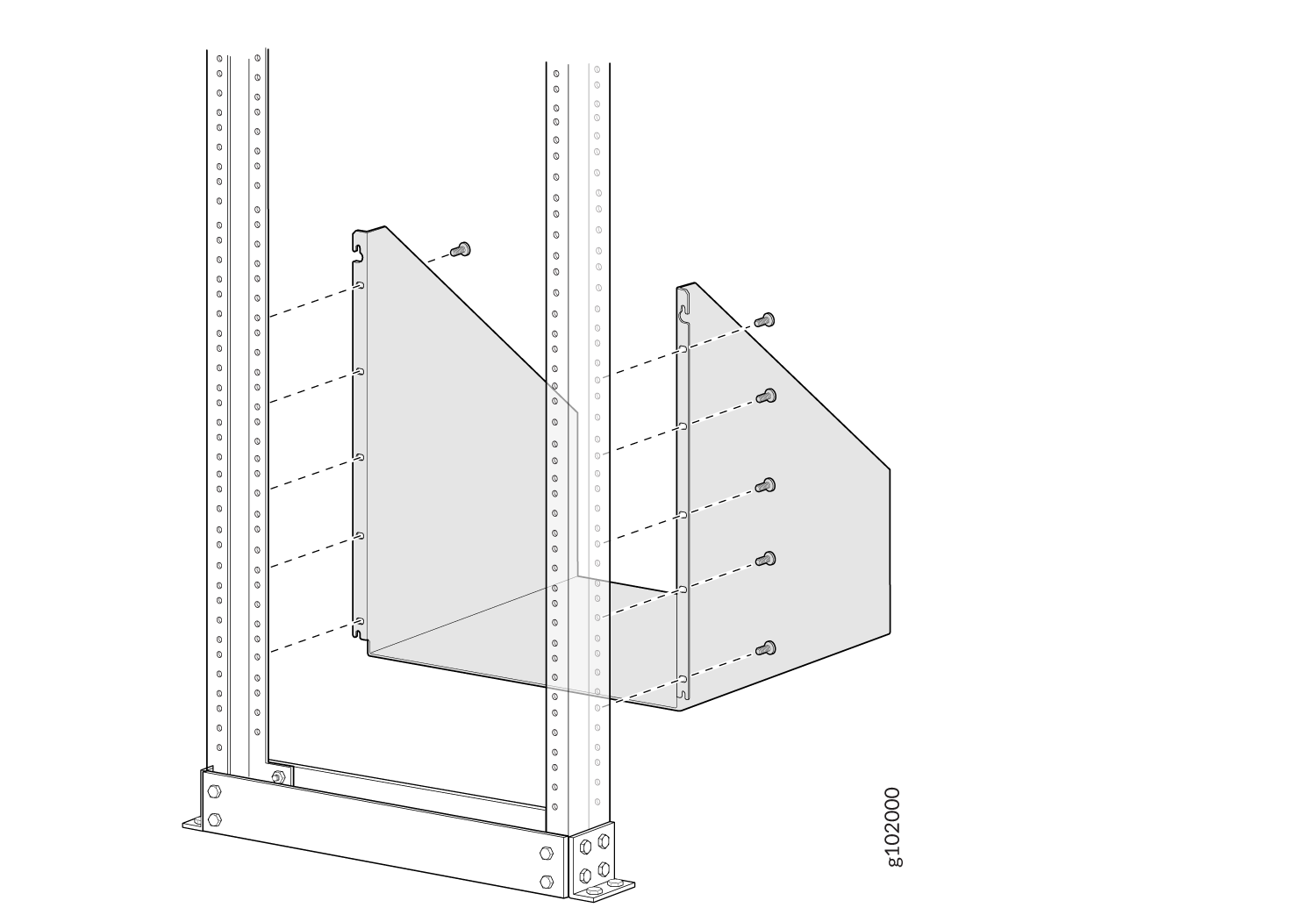
Installing the Open-Frame Rack Mounting Shelf
Before mounting the chassis in an open-frame rack, you must first install the open-frame rack mounting shelf.
To install the open-frame rack mounting shelf (see Figure 3):
- On the rear of each rack rail, partially insert a mounting screw into the highest hole specified in Table 3 for the open-frame rack mounting shelf.
- Install the open-frame rack mounting shelf on the rack. Hang the shelf over the mounting screws by using the keyhole slots located near the top of the shelf flanges.
- Partially insert screws into the open holes in the flanges of the open-frame rack mounting shelf.
- Tighten all the screws completely.
Overview of Installing a PTX5000 Using a Pallet Jack
Before installing the PTX5000 using a pallet jack, verify that you have prepared your site, unpacked the chassis from the shipping crate, and installed the mounting hardware.
Because of the PTX5000 router’s size and weight—up to 1,200 lb (544.3 kg) depending on the configuration (without any FRUs removed)— you must install the PTX5000 using a pallet jack.
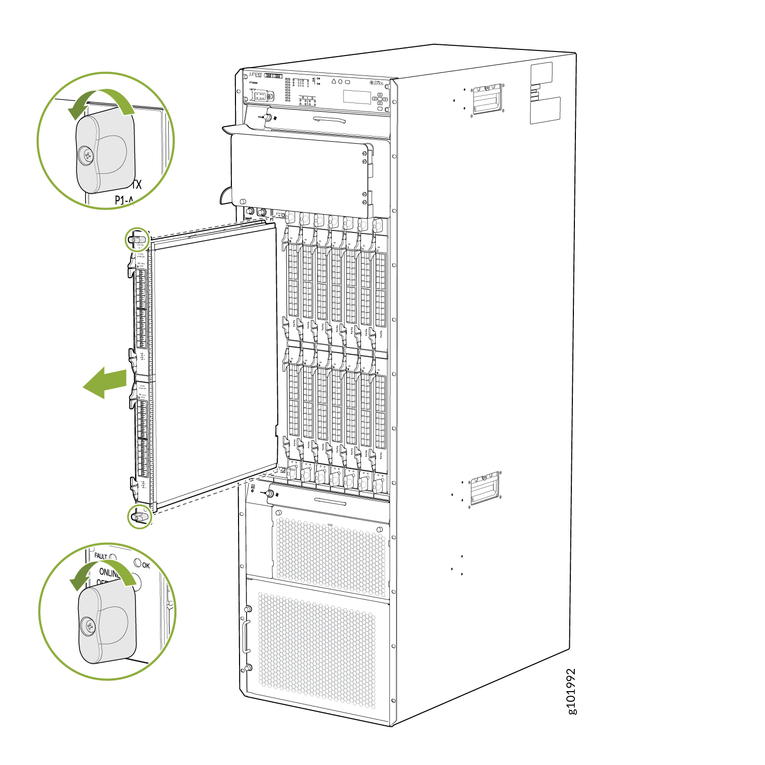
We recommend that you remove the heavy FRU items prior to installing the chassis into the rack.
-
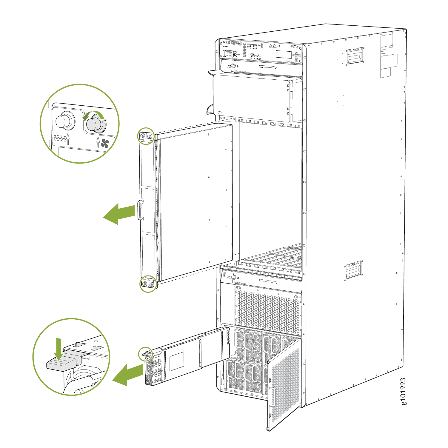
FPCs—24.5 lb (11.1 kg) to 38.5 lb (17.5 kg). See Figure 4 (for detailed instructions, see Replacing a PTX5000 FPC).
-
Vertical fan tray—26.8 lb (12.2 kg), See Figure 5 (for detailed instructions, see Replacing a PTX5000 Vertical Fan Tray).
-
AC PSMs or DC PSMs—10.6 lb (4.8 kg), See Figure 5 (for detailed instructions, see Maintaining the PTX5000 AC Power System or Maintaining the PTX5000 DC Power System).
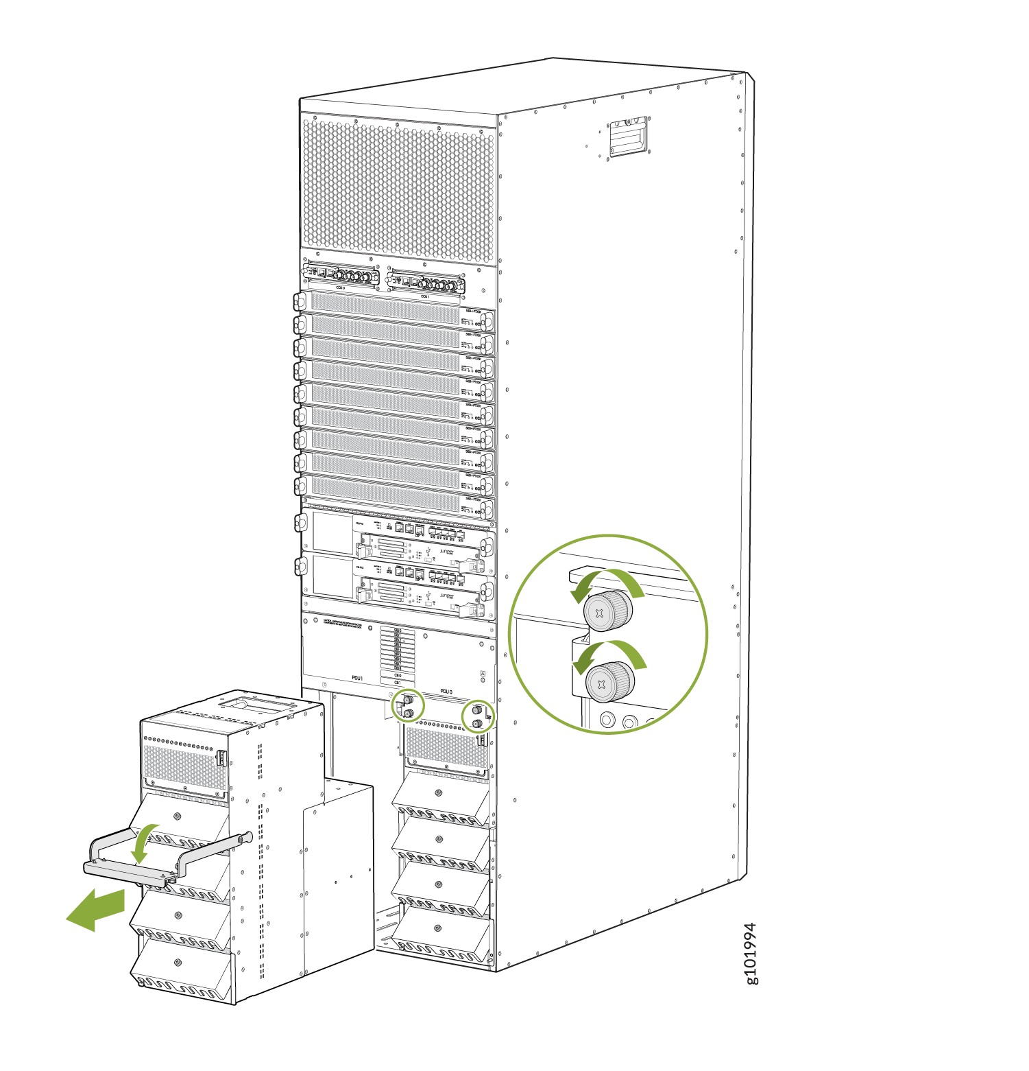
-
AC PDUs or DC PDUs—51.2 lb (23.2 kg) to 64.5 lb (29.3 kg), For detailed instructions, See Figure 6 (for detailed instructions, see Maintaining the PTX5000 AC Power System or Maintaining the PTX5000 DC Power System).
To install the PTX5000:
See Also
Tools Required to Install the PTX5000 Using a Pallet Jack
Gather the tools required to install the PTX5000:
The use of a pallet jack is recommended when positioning the chassis in front of the rack.
Phillips (+) screwdriver, number 2
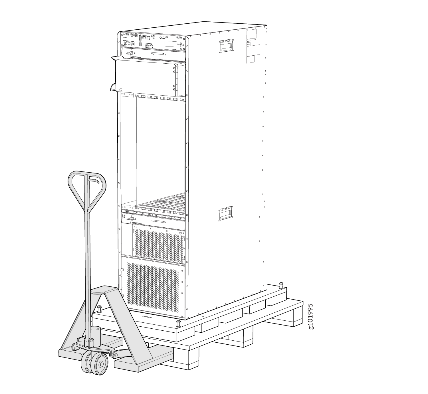
Installing the PTX5000 By Using a Pallet Jack
Before installing the PTX5000:
-
Ensure that a pallet jack is available for the installation. Because of the PTX5000 router’s size and weight—up to 1,200 lb (544.3 kg) depending on configuration—you must use a pallet jack to install the chassis.
-
Have a qualified technician verify that the rack is strong enough to support the chassis weight and is adequately supported at the installation site.
-
We recommend that you have multiple people available to help with the installation of the PTX5000 into the rack.
-
Ensure that the rack is in its permanent location and is secured to the building.
-
Ensure that the installation site allows adequate clearance for both airflow and maintenance.
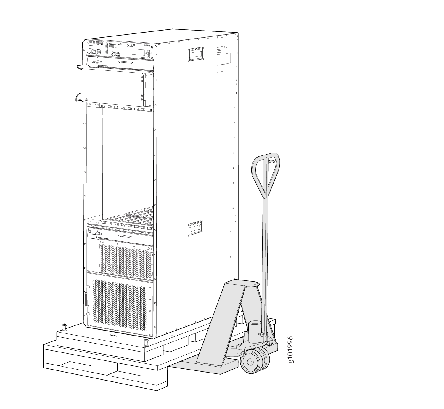
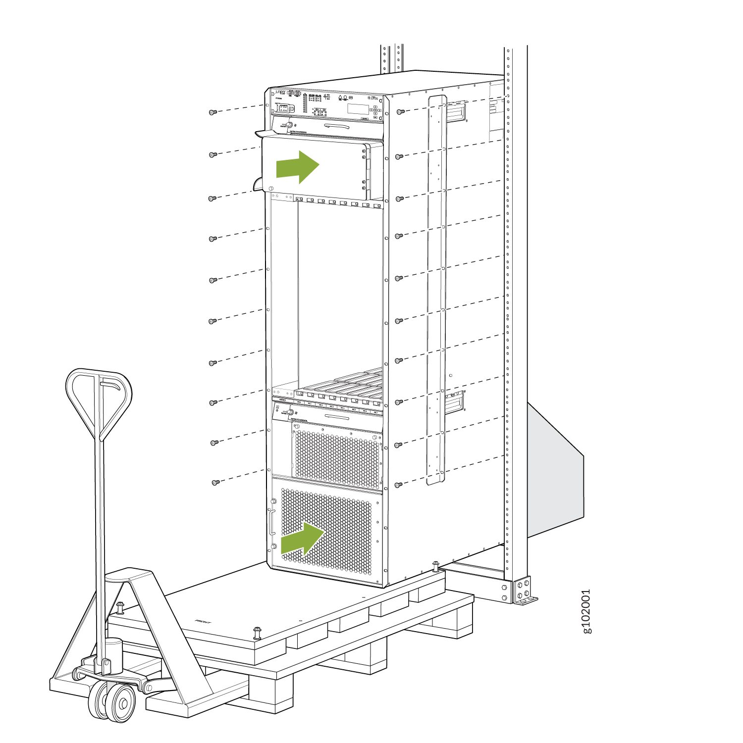
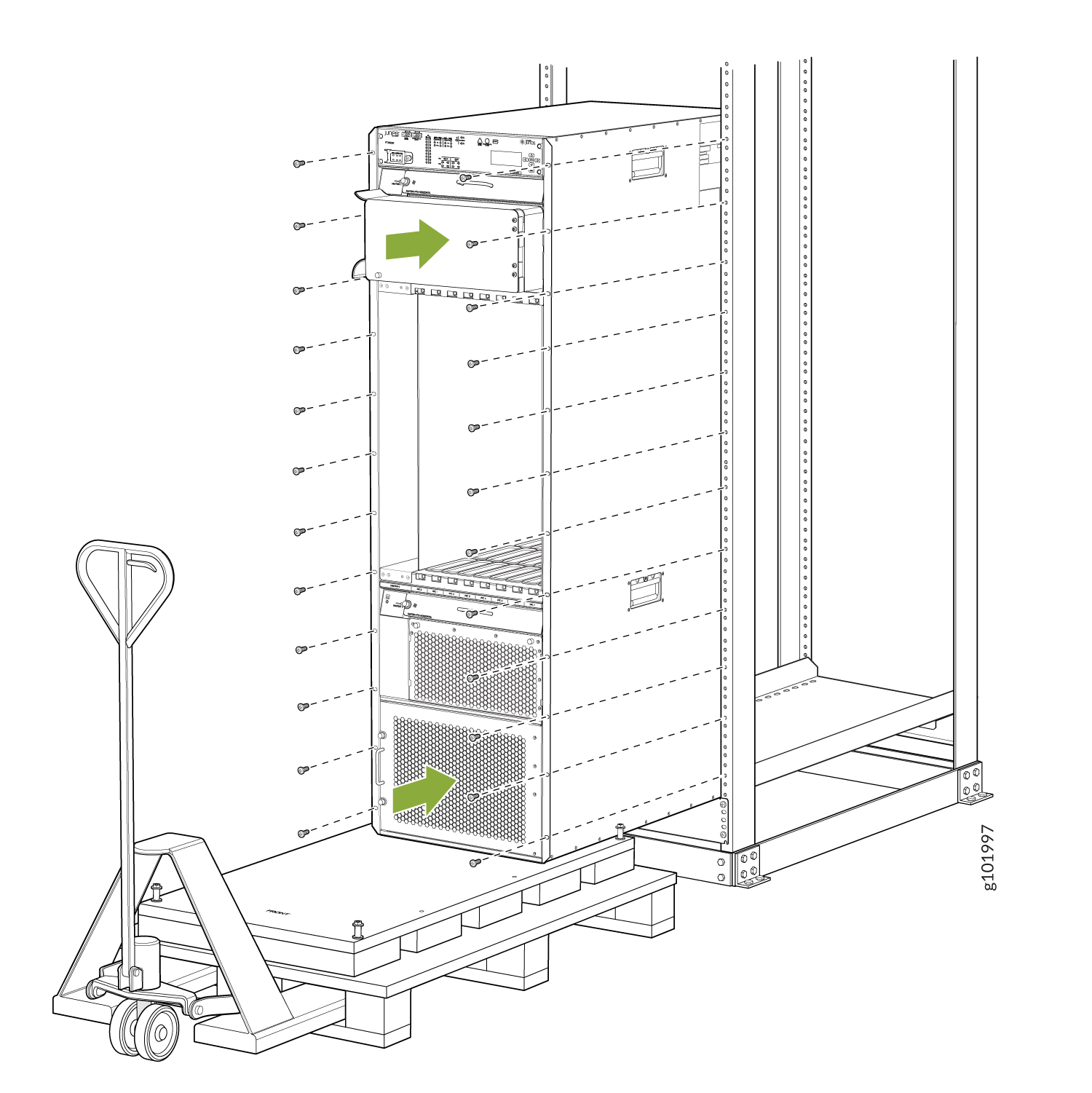
To install the PTX5000 by using a pallet jack (see Figure 7, Figure 8, and Figure 9):
The holes in the center-mounting brackets are spaced at 3 U (5.25 in. or 13.3 cm).
1 — Open-frame rack | 2 — Center-mounting bracket |
The holes in the front-mounting flanges are spaced at 3 U (5.25 in. or 13.3 cm).
1 — Four-post rack | 2 — Front-mounting flange |