Help us improve your experience.

Let us know what you think.

Do you have time for a two-minute survey?


Maintaining PTX5000 Interface Modules

Maintaining the PTX5000 FPCs

Purpose

For optimum PTX5000 performance, verify the condition of the FPCs.

Action

On a regular basis:

  • Check the LEDs on the FPC. During normal operation:

    The green OK LED located the bottom of the FPC lights steadily when the FPC is online and functioning normally. The green OK LED blinks during startup.

  • Issue the CLI show chassis fpc command to check the status of installed FPCs. The value Online in the column labeled State indicates that the FPC is functioning normally.

  • Issue the CLI show chassis environment fpc command to check the temperature and power of installed FPCs. The temperature values should be below the preconfigured thresholds. The power values provide Information about the voltage supplied to the FPC. The left column displays the required power, in volts. The right column displays the measured power, in millivolts.

  • Issue the show chassis fabric topology command. During normal operations, the output for the command shows that the state of the online SIBs and FPCs links are in the OK state.

Holding PTX5000 FPCs

Preventing Damage to FPCs

CAUTION:

Many components on the FPC are fragile. Failure to handle FPCs as specified in this document can cause irreparable damage.

CAUTION:

To prevent damage when handling or carrying FPCs:

  • As you carry the FPC, do not bump it against anything. FPC components are fragile.

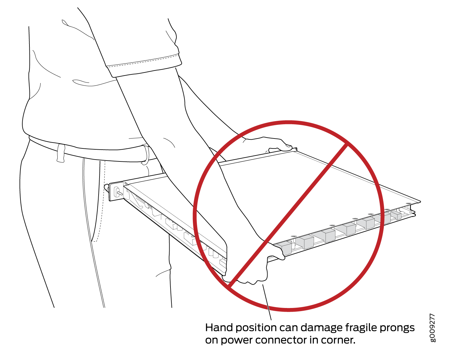
  • Do not grasp the FPC anywhere except places that this document indicates. In particular, never grasp the connector edge, especially at the power connector in the corner where the connector and bottom edges meet (see Figure 1).

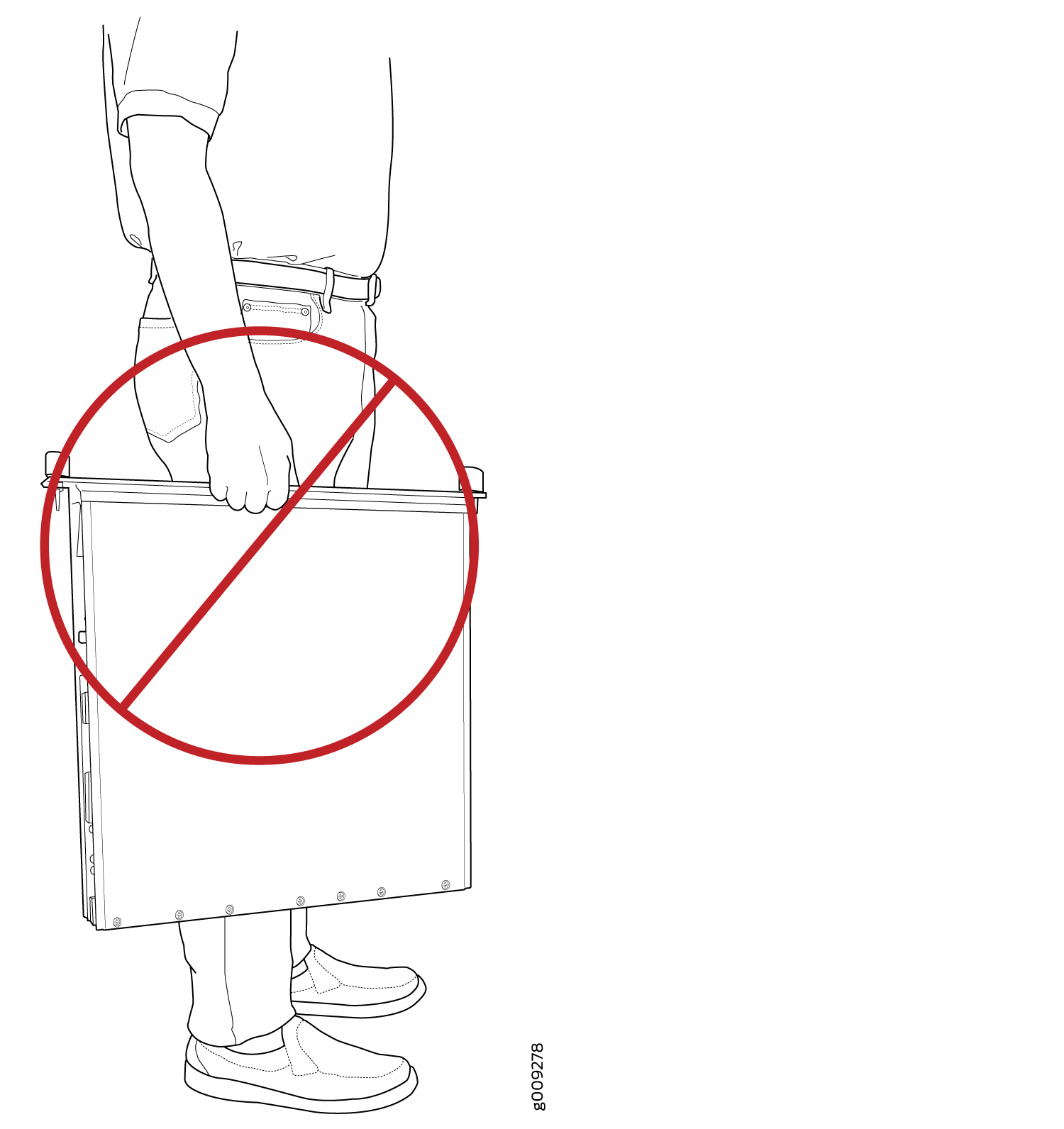
  • Do not carry the FPC by the faceplate with only one hand (see Figure 2).

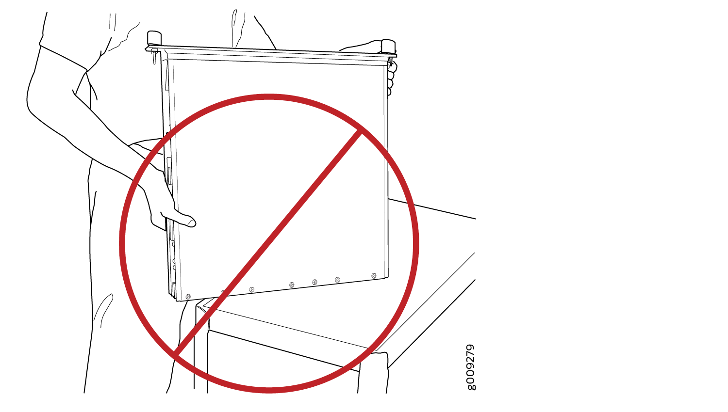
  • Do not rest any edge of an FPC directly against a hard surface (see Figure 3). If you must rest the FPC temporarily on an edge while changing its orientation between vertical and horizontal, use your hand as a cushion between the edge and the surface.

Figure 1: Do Not Grasp the Connector EdgeDo Not Grasp the Connector Edge
Figure 2: Do Not Carry an FPC with Only One HandDo Not Carry an FPC with Only One Hand
Figure 3: Do Not Rest the FPC on an EdgeDo Not Rest the FPC on an Edge

Holding PTX5000 FPCs Vertically

Note:

An FPC configured with PICs installed can weigh as much as 50 lb (22.7 kg). Be prepared to accept the full weight of the FPC as you lift it.

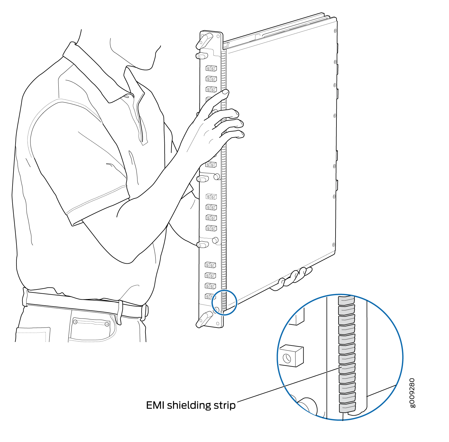
You hold an FPC vertically when installing it into the chassis. To hold an FPC vertically (see Figure 4):

  1. Orient the FPC so that the faceplate faces you.
  2. Place one hand around the FPC faceplate about a quarter of the way down from the top edge. To avoid deforming the electromagnetic interference (EMI) shielding strip, do not press hard on it.
  3. Place your other hand at the bottom edge of the FPC.
Figure 4: Holding an FPC VerticallyHolding an FPC Vertically

Holding PTX5000 FPCs Horizontally

To hold an FPC horizontally:

  1. Orient the FPC so that the faceplate is facing you.
  2. Grasp the top edge with your left hand and the bottom edge with your right hand.

You can rest the faceplate of the FPC against your body as you carry it (see Figure 5).

Figure 5: Holding an FPC HorizontallyHolding an FPC Horizontally

Replacing a PTX5000 FPC

Removing a PTX5000 FPC

The PTX5000 holds up to eight FPCs, which are installed vertically in the front of the PTX5000. An empty FPC weighs between 24.5 lb (11.1 kg) and 38.5 lb (17.5 kg), and an FPC with PICs installed can weigh up to 50 lb (22.7 kg).

Each FPC slot not occupied by an FPC must be covered by an FPC blank panel. An FPC blank panel weighs 6.9 lb (3.1 kg).

To remove an FPC (see Figure 6):

  1. Place an electrostatic bag or antistatic mat on a flat, stable surface.
  2. Attach an electrostatic discharge (ESD) grounding strap to your bare wrist, and connect the strap to one of the ESD points on the chassis.
  3. Use one of the following methods to take the FPC offline:
    • Press and hold the FPC online/offline button. The green OK LED next to the button begins to blink. Hold the button down until the LED goes out.

    • Issue the following CLI command:

  4. Disconnect the cables from the PICs installed in the FPC. Immediately cover each transceiver and the end of each cable with a rubber safety cap. Arrange the disconnected cables in the cable management system, to prevent the cables from developing stress points.
    Warning:

    Do not look directly into a fiber-optic transceiver or into the ends of fiber-optic cables. Fiber-optic transceivers and fiber-optic cable connected to a transceiver emit laser light that can damage your eyes.

    CAUTION:

    Do not leave a fiber-optic transceiver uncovered except when inserting or removing cable. The safety cap keeps the port clean and prevents accidental exposure to laser light.

    CAUTION:

    Avoid bending fiber-optic cable beyond its minimum bend radius. An arc smaller than a few inches in diameter can damage the cable and cause problems that are difficult to diagnose.

  5. If necessary, remove each installed PIC from the FPC.
  6. After you remove each PIC, immediately place it on an antistatic mat or in an electrostatic bag.
  7. Simultaneously turn both the ejector handles counterclockwise to unseat the FPC.
  8. Grasp the handles and slide the FPC straight out of the card cage halfway.
  9. Place one hand around the front of the FPC (the PIC housing) and the other hand under it to support it. Slide the FPC completely out of the chassis, and place it on the antistatic mat or in the electrostatic bag.
    CAUTION:

    The weight of the FPC is concentrated in the back end. Be prepared to accept the full weight—up to 50 lb (22.7 kg) with PICs installed—as you slide the FPC out of the chassis.

    When the FPC is out of the chassis, do not hold it by the ejector handles, bus bars, or edge connectors. They cannot support its weight.

    Do not stack FPCs on top of one another after removal. Place each one individually in an electrostatic bag or on its own antistatic mat on a flat, stable surface. For detailed handling instructions, see Holding PTX5000 FPCs.

  10. If you are not reinstalling a FPC into the emptied FPC slot within a short time, install a blank FPC panel over the slot to maintain proper airflow in the FPC card cage.
    CAUTION:

    After removing an FPC from the chassis, wait at least 30 seconds before reinserting it, removing an FPC from a different slot, or inserting an FPC into a different slot.

Figure 6: Removing an FPCRemoving an FPC

Installing a PTX5000 FPC

CAUTION:

The FPC power connector is located in the corner where the bottom and the connector edges meet. If a power connector prong becomes bent, it no longer aligns with the socket connector on the midplane, and the FPC no longer functions.

To install an FPC (see Figure 7 and Figure 8):

  1. Attach an electrostatic discharge (ESD) grounding strap to your bare wrist, and connect the strap to one of the ESD points on the chassis.
  2. Place the FPC on an antistatic mat.
  3. Take each PIC to be installed in the replacement FPC out of its electrostatic bag and identify the slot on the FPC where it will be connected.
  4. Verify that each fiber-optic PIC has a rubber safety cap covering the PIC transceiver. If it does not, cover the transceiver with a safety cap.
  5. Install each PIC into the appropriate slot on the FPC. For information about installing a PIC, see the installation instructions in Replacing a PTX5000 PIC.
  6. Locate the slot in the FPC card cage in which you plan to install the FPC.
  7. Inspect the slot in the FPC card cage to verify that there are no missing or bent pins on the midplane.
  8. Inspect the FPC to verify that the connectors are not misaligned or damaged.
  9. Orient the FPC vertically with the component side facing to the right. Be sure the FPC is right-side up, with the components on the right of the FPC.
    CAUTION:

    When the FPC is out of the chassis, do not hold it by the ejector handles, bus bars, or edge connectors. They cannot support its weight.

  10. Carefully align the connector edge of the FPC with the appropriate empty slot in the chassis.
  11. Lift the FPC into place and carefully align the bottom and top of the FPC with the guides inside the card cage.
    Figure 7: Installing an FPCInstalling an FPC
  12. Gently rest the bottom edge of the FPC on the bottom edge of the slot opening, making contact a short distance forward of the power connector.
    CAUTION:

    Take care not to bend or otherwise damage the power connector prongs.

  13. Slowly slide the FPC into the slot until you feel resistance.
  14. Align the ejector handles on the FPC faceplate in a position close to horizontal.
  15. Simultaneously turn both ejector handles clockwise until you cannot turn them farther.
  16. Remove the rubber safety cap from each fiber-optic transceiver and fiber-optic cable.
    Laser Warning:

    Do not look directly into a fiber-optic transceiver or into the ends of fiber-optic cables. Fiber-optic transceivers and fiber-optic cable connected to a transceiver emit laser light that can damage your eyes.

  17. Insert the appropriate cable into the cable connector ports on each PIC on the FPC. Secure the cables so that they are not supporting their own weight. Place excess cable out of the way in a neatly coiled loop, using the cable management system. Placing fasteners on a loop helps to maintain its shape.
    CAUTION:

    Do not let fiber-optic cable hang free from the connector. Do not allow fastened loops of cable to dangle, which stresses the cable at the fastening point.

    CAUTION:

    Avoid bending fiber-optic cable beyond its minimum bend radius. An arc smaller than a few inches in diameter can damage the cable and cause problems that are difficult to diagnose.

  18. Use one of the following methods to bring the FPC online:
    • Press and hold the FPC online/offline button until the green OK LED next to the button lights steadily, in about 5 seconds.

    • Issue the following CLI command:

    CAUTION:

    After the OK LED lights steadily, wait at least 30 seconds before removing the FPC again, removing an FPC from a different slot, or inserting an FPC in a different slot.

You can also verify correct FPC and PIC functioning by issuing the show chassis fpc and show chassis fpc pic-status commands, as described in Maintaining the PTX5000 FPCs.

Figure 8: Connecting Fiber-Optic Cable to a PICConnecting Fiber-Optic Cable to a PIC

Maintaining the PTX5000 PICs

Purpose

For optimum performance, verify the condition of the PICs.

Action

On a regular basis:

  • Check the LEDs on PIC faceplates. The meaning of the LED states differs for various PICs. For more information, see the PTX Series Interface Module Reference. If the FPC that houses the PIC detects a PIC failure, the FPC generates an alarm message to be sent to the Routing Engine.

    A PIC LED lit green indicates that the PIC is functioning normally.

  • Issue the CLI show chassis fpc pic-status command. The PIC slots in an FPC are numbered from 0 through 1, top to bottom.

Replacing a PTX5000 PIC

Removing a PTX5000 PIC

PICs are hot-insertable and hot-removable. When you remove a PIC, the PTX5000 continues to function, although the PIC interfaces being removed no longer function.

The PICs are located in the FPCs installed in the front of the PTX5000. A PIC weighs approximately 5 lb (2.3 kg).

To remove a PIC:

  1. Place an electrostatic bag or antistatic mat on a flat, stable surface to receive the PIC. If the PIC connects to fiber-optic cable, have ready a rubber safety cap for each transceiver and cable.
  2. Attach an electrostatic discharge ESD grounding strap to your bare wrist, and connect the strap to one of the ESD points on the chassis.
  3. Use one of the following methods to take the PIC offline:
    • Press and hold the online/offline button until the PIC LED goes out (about 5 seconds).

    • Issue the following CLI command:

  4. Label the cables connected to the PIC so that you can later reconnect each cable to the correct PIC.
  5. Disconnect the cables from the PIC. Immediately cover each transceiver and the end of each fiber-optic cable with a rubber safety cap.
    Laser Warning:

    Do not look directly into a fiber-optic transceiver or into the ends of fiber-optic cables. Fiber-optic transceivers and fiber-optic cable connected to a transceiver emit laser light that can damage your eyes.

    CAUTION:

    Do not leave a fiber-optic transceiver uncovered except when inserting or removing cable. The safety cap keeps the port clean and prevents accidental exposure to laser light.

  6. Arrange the cable in the cable management system to prevent it from dislodging or developing stress points. Secure the cable so that it is not supporting its own weight as it hangs to the floor. Place excess cable out of the way in a neatly coiled loop in the cable management system. Placing fasteners on the loop helps to maintain its shape.
    CAUTION:

    Avoid bending fiber-optic cable beyond its minimum bend radius. An arc smaller than a few inches in diameter can damage the cable and cause problems that are difficult to diagnose.

  7. Unseat the PIC: Flip the ejector handles outward.
  8. Slide the PIC out of the FPC card carrier, and place it in the electrostatic bag or on the antistatic mat.
  9. If you are not reinstalling a PIC into the emptied PIC slot within a short time, install a blank PIC panel over the slot to maintain proper airflow in the FPC card cage.

Installing a PTX5000 PIC

To install a PIC:

  1. Attach an electrostatic discharge (ESD) grounding strap to your bare wrist, and connect the strap to one of the ESD points on the chassis.
  2. Verify that there is a rubber safety cap over each fiber-optic transceiver on the faceplate. Install a cap if necessary.
  3. Align the notches in the connector at the rear of the PIC with the notches in the PIC slot in the FPC and then slide the PIC in until it lodges firmly in the FPC.
    CAUTION:

    Slide the PIC straight into the slot to avoid damaging the components on the bottom of the PIC.

  4. Secure the PIC to the FPC faceplate: Grasp both ejector handles and press them inward to seat the PIC until the ejectors latch into the FPC.
  5. Remove the rubber safety cap from each fiber-optic transceiver and the end of each fiber-optic cable.
    Laser Warning:

    Do not look directly into a fiber-optic transceiver or into the ends of fiber-optic cables. Fiber-optic transceivers and fiber-optic cable connected to a transceiver emit laser light that can damage your eyes.

    CAUTION:

    Do not leave a fiber-optic transceiver uncovered except when inserting or removing cable. The safety cap keeps the port clean and prevents accidental exposure to laser light.

  6. Insert the appropriate cables into the cable connectors on the PIC.
  7. Arrange each cable in the cable management system to prevent the cable from dislodging or developing stress points. Secure the cable so that it is not supporting its own weight as it hangs to the floor. Place excess cable out of the way in a neatly coiled loop in the cable management system. Placing fasteners on the loop helps to maintain its shape.
    CAUTION:

    Do not let fiber-optic cable hang free from the connector. Do not allow fastened loops of cable to dangle, which stresses the cable at the fastening point.

    CAUTION:

    Avoid bending fiber-optic cable beyond its minimum bend radius. An arc smaller than a few inches in diameter can damage the cable and cause problems that are difficult to diagnose.

  8. Use one of the following methods to bring the PIC online:
    • Press the PIC offline/online button until the PIC LED lights green.

    • Issue the following CLI command:

    The normal functioning status LED confirms that the PIC is online. You can also verify correct PIC functioning by issuing the show chassis fpc pic-status command.

Maintaining the PTX5000 PIC Cables

Purpose

For optimum performance, verify the condition of the cables.

Action

  • Use the cable management system (shown in PTX5000 Cable Management System) to support cables and prevent cables from dislodging or developing stress points.

  • Place excess cable out of the way in the cable management system. Do not allow fastened loops of cable to dangle from the connector or cable management system, because this stresses the cable at the fastening point. Putting fasteners on the loops helps to maintain their shape.

  • Keep the cable connections clean and free of dust and other particles, which can cause drops in the received power level. Always inspect cables and clean them if necessary before connecting an interface.

  • Label both ends of the cables to identify them.

  • When you unplug a fiber-optic cable from a transceiver, always place a rubber safety plug over the transceiver on the faceplate and on the end of the cable.

  • Anchor fiber-optic cable to avoid stress on the connectors. When attaching fiber to a transceiver, be sure to secure the fiber so it is not supporting its own weight as it hangs to the floor. Never let fiber-optic cable hang free from the connector.

  • Avoid bending fiber-optic cable beyond its bend radius. An arc smaller than a few inches can damage the cable and cause problems that are difficult to diagnose.

  • Frequent plugging and unplugging of fiber-optic cable into and out of optical instruments, such as analyzers, can cause damage to the instruments that is expensive to repair. Instead, attach a short fiber extension to the optical equipment. Any wear and tear due to frequent plugging and unplugging is then absorbed by the short fiber extension, which is easy and inexpensive to replace.

  • Keep fiber-optic cable connections clean. Small microdeposits of oil and dust in the canal of the transceiver or cable connector could cause loss of light, reducing signal power and possibly causing intermittent problems with the optical connection.

Replacing a PTX5000 PIC Cable

Removing a PTX5000 PIC Cable

Removing and installing PIC cables does not affect router functionality, except that a PIC does not receive or transmit data while its cable is disconnected. To remove a PIC cable:

  1. Have ready a rubber safety cap for each fiber-optic cable and fiber-optic transceiver.
  2. If removing all cables connected to the PIC, use one of the following methods to take the PIC offline:
    • Press its online/offline button.

    • Issue the following CLI command:

  3. Unplug the cable from the cable connector port. Immediately cover each fiber-optic transceiver and the end of each fiber-optic cable with a rubber safety cap.
    Laser Warning:

    Do not look directly into a fiber-optic transceiver or into the ends of fiber-optic cables. Fiber-optic transceivers and fiber-optic cable connected to a transceiver emit laser light that can damage your eyes.

    CAUTION:

    Do not leave a fiber-optic transceiver uncovered except when inserting or removing cable. The safety cap keeps the port clean and prevents accidental exposure to laser light.

  4. Remove the cable from the cable management system and detach it from the destination port.

Installing a PTX5000 PIC Cable

To install a PIC cable (see Figure 9):

  1. Have ready a length of the type of cable used by the PIC. For cable specifications, see the PTX Series Interface Module Reference.
  2. Remove the rubber safety plug from the PIC cable connector port.
    Laser Warning:

    Do not look directly into a fiber-optic transceiver or into the ends of fiber-optic cables. Fiber-optic transceivers and fiber-optic cable connected to a transceiver emit laser light that can damage your eyes.

    CAUTION:

    Do not leave a fiber-optic transceiver uncovered except when inserting or removing cable. The safety cap keeps the port clean and prevents accidental exposure to laser light.

  3. Insert the cable connector into the cable connector port on the PIC faceplate.
  4. Arrange the cable in the cable management system, to prevent it from dislodging or developing stress points. Secure the cable so that it is not supporting its own weight as it hangs to the floor. Place excess cable out of the way in a neatly coiled loop in the cable management system. Placing fasteners on the loop helps to maintain its shape.
    CAUTION:

    Avoid bending fiber-optic cable beyond its minimum bend radius. An arc smaller than a few inches in diameter can damage the cable and cause problems that are difficult to diagnose.

    CAUTION:

    Do not let fiber-optic cable hang free from the connector. Do not allow fastened loops of cable to dangle, which stresses the cable at the fastening point.

  5. Insert the other end of the cable into the destination port.
  6. Repeat the previous steps for any additional cables.
  7. If the PIC is offline (its failure indicator LED is lit), use one of the following methods to bring the PIC online:
    • Press the PIC offline/online button until the PIC LED lights green.

    • Issue the following CLI command:

    The normal functioning indicator LED confirms that the PIC is online. You can also verify correct PIC functioning by issuing the show chassis fpc pic-status command.

Figure 9: Connecting Fiber-Optic Cable to a PICConnecting Fiber-Optic Cable to a PIC

Replacing a PTX5000 PIC CFP Transceiver

Removing a PTX5000 PIC CFP Transceiver

C form-factor pluggables (CFPs) are transceivers that can be removed from a PIC. CFP transceivers are hot-insertable and hot-removable. Removing a CFP transceiver does not interrupt PIC functioning, but the removed CFP transceiver no longer receives or transmits data.

To remove a CFP transceiver:

  1. Place an electrostatic bag or antistatic mat on a flat, stable surface to receive the CFP transceiver. Have ready a rubber safety cap for the CFP transceiver and the cable.
  2. Attach an electrostatic discharge (ESD) grounding strap to your bare wrist, and connect the strap to one of the ESD points on the chassis.
  3. Label the cable connected to the CFP transceiver so that you can later reconnect it to the correct CFP transceiver.
  4. Disconnect the cable from the CFP transceiver. Immediately cover the transceiver and the end of the cable with a rubber safety cap.
    Laser Warning:

    Do not look directly into a fiber-optic transceiver or into the ends of fiber-optic cables. Fiber-optic transceivers and fiber-optic cable connected to a transceiver emit laser light that can damage your eyes.

    CAUTION:

    Do not leave a fiber-optic transceiver uncovered except when inserting or removing cable. The safety cap keeps the port clean and prevents accidental exposure to laser light.

  5. Arrange the cable in the cable management system to prevent it from dislodging or developing stress points. Secure the cable so that it is not supporting its own weight as it hangs to the floor. Place excess cable out of the way in a neatly coiled loop in the cable management system. Placing fasteners on the loop helps to maintain its shape.
    CAUTION:

    Avoid bending fiber-optic cable beyond its minimum bend radius. An arc smaller than a few inches in diameter can damage the cable and cause problems that are difficult to diagnose.

  6. Pull the ejector handle away from the CFP transceiver faceplate to unseat the CFP transceiver from the PIC. Pull the CFP transceiver out of the PIC and place it on the antistatic mat or in the electrostatic bag.

Installing a PTX5000 PIC CFP Transceiver

To install a replacement CFP:

  1. Attach an electrostatic discharge (ESD) grounding strap to your bare wrist, and connect the strap to one of the ESD points on the chassis.
  2. Verify that a rubber safety cap covers the CFP transceiver, installing one if necessary.
  3. Orient the CFP over the port in the PIC so that the connector end will enter the slot first and the CFP connector faces the appropriate direction.
  4. Slide the CFP into the slot. If there is resistance, remove the CFP and flip it so that the connector faces the other direction.
  5. Remove the rubber safety cap from the transceiver and the end of the cable, and insert the cable into the transceiver.
    Laser Warning:

    Do not look directly into a fiber-optic transceiver or into the ends of fiber-optic cables. Fiber-optic transceivers and fiber-optic cable connected to a transceiver emit laser light that can damage your eyes.

    CAUTION:

    Do not leave a fiber-optic transceiver uncovered except when inserting or removing cable. The safety cap keeps the port clean and prevents accidental exposure to laser light.

  6. Arrange the cable in the cable management system to prevent the cable from dislodging or developing stress points. Secure the cable so that it is not supporting its own weight as it hangs to the floor. Place excess cable out of the way in a neatly coiled loop in the cable management system. Placing fasteners on the loop helps to maintain its shape.
    CAUTION:

    Do not let fiber-optic cable hang free from the connector. Do not allow fastened loops of cable to dangle, which stresses the cable at the fastening point.

    CAUTION:

    Avoid bending fiber-optic cable beyond its minimum bend radius. An arc smaller than a few inches in diameter can damage the cable and cause problems that are difficult to diagnose.

  7. Verify that the status LEDs on the PIC faceplate indicate that the CFP is functioning correctly. For more information about the PIC LEDs, see the PTX Series Interface Module Reference. You can also verify PIC functioning by issuing the show chassis fpc pic-status command.

Replacing a CFP2 Transceiver

Removing a CFP2 Transceiver

C form-factor pluggables (CFPs) are transceivers that can be removed from a PIC. CFP2 transceivers are hot-insertable and hot-removable. Removing a CFP2 transceiver does not interrupt PIC functioning, but the removed CFP2 transceiver no longer receives or transmits data.

Figure 10: Form-Factor Pluggable (CFP2)Form-Factor Pluggable (CFP2)

To remove a CFP2 transceiver (see Figure 10):

  1. Place an electrostatic bag or antistatic mat on a flat, stable surface to receive the CFP transceiver. Have ready a rubber safety cap for the CFP2 transceiver and the cable.
  2. Attach an electrostatic discharge (ESD) grounding strap to your bare wrist, and connect the strap to one of the ESD points on the chassis.
  3. Label the cable connected to the CFP2 transceiver so that you can later reconnect it to the correct CFP2 transceiver.
  4. Disconnect the cable from the CFP2 transceiver. Immediately cover the transceiver and the end of the cable with a rubber safety cap.
    Laser Warning:

    Do not look directly into a fiber-optic transceiver or into the ends of fiber-optic cables. Fiber-optic transceivers and fiber-optic cable connected to a transceiver emit laser light that can damage your eyes.

    CAUTION:

    Do not leave a fiber-optic transceiver uncovered except when inserting or removing cable. The safety cap keeps the port clean and prevents accidental exposure to laser light.

  5. Arrange the cable in the cable management system to prevent it from dislodging or developing stress points. Secure the cable so that it is not supporting its own weight as it hangs to the floor. Place excess cable out of the way in a neatly coiled loop in the cable management system. Placing fasteners on the loop helps to maintain its shape.
    CAUTION:

    Avoid bending fiber-optic cable beyond its minimum bend radius. An arc smaller than a few inches in diameter can damage the cable and cause problems that are difficult to diagnose.

  6. Pull the ejector latch to the extreme end away from the CFP2 transceiver faceplate to unseat the CFP2 transceiver from the PIC. Pull the CFP2 transceiver out of the PIC and place it on the antistatic mat or in the electrostatic bag.
    Note:

    You cannot remove the transceiver until you move the ejector latch to the extreme end.

Installing a CFP2 Transceiver

To install a replacement CFP2:

  1. Attach an electrostatic discharge (ESD) grounding strap to your bare wrist, and connect the strap to one of the ESD points on the chassis.
  2. Verify that a rubber safety cap covers the CFP transceiver, installing one if necessary.
  3. Orient the CFP2 over the port in the PIC so that the connector end will enter the slot first and the CFP2 connector faces the appropriate direction.
  4. Slide the CFP2 into the slot. If there is resistance, remove the CFP2 and flip it so that the connector faces the other direction.
  5. Remove the rubber safety cap from the transceiver and the end of the cable, and insert the cable into the transceiver.
    Laser Warning:

    Do not look directly into a fiber-optic transceiver or into the ends of fiber-optic cables. Fiber-optic transceivers and fiber-optic cable connected to a transceiver emit laser light that can damage your eyes.

    CAUTION:

    Do not leave a fiber-optic transceiver uncovered except when inserting or removing cable. The safety cap keeps the port clean and prevents accidental exposure to laser light.

  6. Arrange the cable in the cable management system to prevent the cable from dislodging or developing stress points. Secure the cable so that it is not supporting its own weight as it hangs to the floor. Place excess cable out of the way in a neatly coiled loop in the cable management system. Placing fasteners on the loop helps to maintain its shape.
    CAUTION:

    Do not let fiber-optic cable hang free from the connector. Do not allow fastened loops of cable to dangle, which stresses the cable at the fastening point.

    CAUTION:

    Avoid bending fiber-optic cable beyond its minimum bend radius. An arc smaller than a few inches in diameter can damage the cable and cause problems that are difficult to diagnose.

  7. Verify that the status LEDs on the PIC faceplate indicate that the CFP2 is functioning correctly. You can also verify PIC functioning by issuing the show chassis fpc pic-status command.

Replacing a PTX5000 PIC SFP+ Transceiver

Removing a PTX5000 PIC SFP+ Transceiver

Small form-factor pluggables (SFPs) are transceivers that can be removed from a PIC. SFPs are hot-insertable and hot-removable. Removing an SFP does not interrupt PIC functioning, but the removed SFP no longer receives or transmits data.

Figure 11: Small Form-Factor Pluggable (SFP)Small Form-Factor Pluggable (SFP)

To remove an SFP+ transceiver (see Figure 11):

  1. Place an electrostatic bag or antistatic mat on a flat, stable surface to receive the SFP+. Have ready a rubber safety cap for the SFP+ transceiver and the cable.
  2. Attach an electrostatic discharge (ESD) grounding strap to your bare wrist, and connect the strap to one of the ESD points on the chassis.
  3. Label the cable connected to the SFP+ so that you can later reconnect it to the correct SFP+.
  4. Disconnect the cable from the SFP+. Immediately cover the transceiver and the end of the cable with a rubber safety cap.
    Laser Warning:

    Do not look directly into a fiber-optic transceiver or into the ends of fiber-optic cables. Fiber-optic transceivers and fiber-optic cable connected to a transceiver emit laser light that can damage your eyes.

    CAUTION:

    Do not leave a fiber-optic transceiver uncovered except when inserting or removing cable. The safety cap keeps the port clean and prevents accidental exposure to laser light.

  5. Arrange the cable in the cable management system to prevent it from dislodging or developing stress points. Secure the cable so that it is not supporting its own weight as it hangs to the floor. Place excess cable out of the way in a neatly coiled loop in the cable management system. Placing fasteners on the loop helps to maintain its shape.
    CAUTION:

    Avoid bending fiber-optic cable beyond its minimum bend radius. An arc smaller than a few inches in diameter can damage the cable and cause problems that are difficult to diagnose.

  6. Pull the ejector handle away from the SFP+ faceplate to unseat the SFP+ from the PIC. Pull the SFP+ out of the PIC and place it on the antistatic mat or in the electrostatic bag.

Installing a PTX5000 PIC SFP+ Transceiver

To install a replacement SFP+:

  1. Attach an electrostatic discharge (ESD) grounding strap to your bare wrist, and connect the strap to one of the ESD points on the chassis.
  2. Verify that a rubber safety cap covers the SFP+ transceiver, installing one if necessary.
  3. Orient the SFP+ over the port in the PIC so that the connector end will enter the slot first and the SFP+ connector faces the appropriate direction.
  4. Slide the SFP+ into the slot. If there is resistance, remove the SFP+ and flip it so that the connector faces the other direction.
  5. Remove the rubber safety cap from the transceiver and the end of the cable, and insert the cable into the transceiver.
    Laser Warning:

    Do not look directly into a fiber-optic transceiver or into the ends of fiber-optic cables. Fiber-optic transceivers and fiber-optic cable connected to a transceiver emit laser light that can damage your eyes.

    CAUTION:

    Do not leave a fiber-optic transceiver uncovered except when inserting or removing cable. The safety cap keeps the port clean and prevents accidental exposure to laser light.

  6. Arrange the cable in the cable management system to prevent the cable from dislodging or developing stress points. Secure the cable so that it is not supporting its own weight as it hangs to the floor. Place excess cable out of the way in a neatly coiled loop in the cable management system. Placing fasteners on the loop helps to maintain its shape.
    CAUTION:

    Do not let fiber-optic cable hang free from the connector. Do not allow fastened loops of cable to dangle, which stresses the cable at the fastening point.

    CAUTION:

    Avoid bending fiber-optic cable beyond its minimum bend radius. An arc smaller than a few inches in diameter can damage the cable and cause problems that are difficult to diagnose.

  7. Verify that the status LEDs on the PIC faceplate indicate that the PIC is functioning correctly. For more information about the PIC LEDs, see the PTX Series Interface Module Reference. You can also verify PIC functioning by issuing the show chassis fpc pic-status command.

Replacing a QSFP28 Transceiver

Removing a QSFP28 Transceiver

28-Gbps quad small form-factor pluggable (QSFP28) are transceivers that can be removed from a PIC. QSFP28 transceivers are hot-insertable and hot-removable. Removing a QSFP28 transceiver does not interrupt PIC functioning, but the removed QSFP28 transceiver no longer receives or transmits data.

Figure 12: 28-Gbps Quad Small Form-Factor Pluggable (QSFP28) 28-Gbps Quad Small Form-Factor Pluggable (QSFP28)

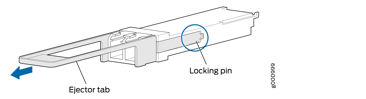
To remove a QSFP28 transceiver (see Figure 12):

  1. Place an electrostatic bag or antistatic mat on a flat, stable surface to receive the QSFP28 transceiver. Have ready a rubber safety cap for the QSFP28 transceiver and the cable.
  2. Attach an electrostatic discharge (ESD) grounding strap to your bare wrist, and connect the strap to one of the ESD points on the chassis.
  3. Label the cable connected to the QSFP28 transceiver so that you can later reconnect it to the correct QSFP28 transceiver.
  4. Disconnect the cable from the QSFP28 transceiver. Immediately cover the transceiver and the end of the cable with a rubber safety cap.
    Laser Warning:

    Do not look directly into a fiber-optic transceiver or into the ends of fiber-optic cables. Fiber-optic transceivers and fiber-optic cable connected to a transceiver emit laser light that can damage your eyes.

    CAUTION:

    Do not leave a fiber-optic transceiver uncovered except when inserting or removing cable. The safety cap keeps the port clean and prevents accidental exposure to laser light.

  5. Arrange the cable in the cable management system to prevent it from dislodging or developing stress points. Secure the cable so that it is not supporting its own weight as it hangs to the floor. Place excess cable out of the way in a neatly coiled loop in the cable management system. Placing fasteners on the loop helps to maintain its shape.
    CAUTION:

    Avoid bending fiber-optic cable beyond its minimum bend radius. An arc smaller than a few inches in diameter can damage the cable and cause problems that are difficult to diagnose.

  6. Pull the transceiver’s rubber handle straight back. The locking pins on the transceiver automatically release. Place the transceiver on the antistatic mat or in the electrostatic bag.

Installing a QSFP28 Transceiver

To install a replacement QSFP28:

  1. Attach an electrostatic discharge (ESD) grounding strap to your bare wrist, and connect the strap to one of the ESD points on the chassis.
  2. Verify that a rubber safety cap covers the QSFP28 transceiver, installing one if necessary.
  3. Orient the QSFP28 over the port in the PIC so that the QSFP28 connector faces the appropriate direction.
  4. Slide the QSFP28 into the slot until the locking pins lock in place. If there is resistance, remove the QSFP28 and flip it so that the connector faces the other direction.
  5. Remove the rubber safety cap from the transceiver and the end of the cable, and insert the cable into the transceiver.
    Laser Warning:

    Do not look directly into a fiber-optic transceiver or into the ends of fiber-optic cables. Fiber-optic transceivers and fiber-optic cable connected to a transceiver emit laser light that can damage your eyes.

    CAUTION:

    Do not leave a fiber-optic transceiver uncovered except when inserting or removing cable. The safety cap keeps the port clean and prevents accidental exposure to laser light.

  6. Arrange the cable in the cable management system to prevent the cable from dislodging or developing stress points. Secure the cable so that it is not supporting its own weight as it hangs to the floor. Place excess cable out of the way in a neatly coiled loop in the cable management system. Placing fasteners on the loop helps to maintain its shape.
    CAUTION:

    Do not let fiber-optic cable hang free from the connector. Do not allow fastened loops of cable to dangle, which stresses the cable at the fastening point.

    CAUTION:

    Avoid bending fiber-optic cable beyond its minimum bend radius. An arc smaller than a few inches in diameter can damage the cable and cause problems that are difficult to diagnose.

  7. Verify that the status LEDs on the PIC faceplate indicate that the QSFP28 is functioning correctly. For more information about the PIC LEDs, see the PTX Series Interface Module Reference. You can also verify PIC functioning by issuing the show chassis fpc pic-status command.