PTX5000 Site Guidelines and Requirements
PTX5000 Environmental Specifications
Table 1 specifies the environmental specifications required for normal PTX5000 operation. In addition, the site should be as dust-free as possible.
Description |
Value |
|---|---|
Altitude |
No performance degradation to 10,000 ft (3048 m) |
Relative humidity |
Normal operation ensured in relative humidity range of 5% to 90%, noncondensing |
Temperature |
Normal operation ensured in temperature range of 32°F (0°C) to 104°F (40°C) Nonoperating storage temperature in shipping crate: –40°F (–40°C) to 158°F (70°C) |
Seismic |
Designed to meet Telcordia Technologies Zone 4 earthquake requirements |
Maximum thermal output |
|
Install the PTX5000 only in restricted areas, such as dedicated equipment rooms and equipment closets, in accordance with Articles 110-16, 110-17, and 110-18 of the National Electrical Code, ANSI/NFPA 70.
See Also
General Site Guidelines
Efficient device operation requires proper site planning and maintenance. It also requires proper layout of the equipment, rack or cabinet, and wiring closet.
To plan and create an acceptable operating environment for your device and prevent environmentally caused equipment failures:
Keep the area around the chassis free from dust and conductive material, such as metal flakes.
Follow prescribed airflow guidelines to ensure that the cooling system functions properly. Ensure that exhaust from other equipment does not blow into the intake vents of the device.
Follow the prescribed electrostatic discharge (ESD) prevention procedures to prevent damaging the equipment. Static discharge can cause components to fail completely or intermittently over time.
Install the device in a secure area, so that only authorized personnel can access the device.
PTX5000 Chassis Grounding Cable and Lug Specifications
To meet safety and electromagnetic interference (EMI) requirements and to ensure proper operation, the PTX5000 must be adequately grounded before power is connected.
Two pairs of threaded inserts (PEM nuts) are provided on the right rear of the chassis for connecting the packet transport to earth ground. The top pair of grounding points fits M6 screws (European), and the bottom pair fits UNC 1/4–20 screws (American). The grounding points are spaced at 0.625-in. (15.86-mm) centers.
The accessory kit shipped with the PTX5000 includes:
-
Two UNC 1/4–20 screws used to secure the grounding cable to the bottom grounding points.
-
Depending on your configuration:
-
60-A DC PDU—4-AWG (21.2 mm2) cable lugs for connecting DC power and grounding the PTX5000 (see Figure 2).
-
120-A DC PDU—0-AWG (53 mm2) cable lugs for connecting DC power and grounding the PTX5000 (see Figure 1).
-
High Capacity DC PDU—4-AWG (21.2 mm2) cable lugs for connecting DC power and grounding the PTX5000 (see Figure 2).
-
Before device installation begins, a licensed electrician must attach a cable lug to the grounding cable that you supply. A cable with an incorrectly attached lug can damage the PTX5000.
You must install the PTX5000 in a restricted-access location and ensure that the chassis is always properly grounded. The PTX5000 has a two-hole protective grounding terminal provided on the chassis. Under all circumstances, use this grounding connection to ground the chassis. For AC-powered systems, you must also use the grounding wire in the AC power cord along with the two-hole grounding lug connection. This tested system meets or exceeds all applicable EMC regulatory requirements with the two-hole protective grounding terminal.
You must supply a grounding cable. Table 2 summarizes the specifications for the grounding cable and lug.
|
Item |
Specification |
|---|---|
|
Grounding cable |
The grounding cable must be equivalent in size or larger—have a greater current-carrying capacity—than the power cables connected to the PDUs. |
|
Grounding connector |
Cable lug; dual hole, sized to fit 1/4-20 UNC terminal studs at 15.86-mm (0.625-in.) center line. |
In addition, GR1089-CORE requires the following:
-
The grounding conductor must be copper.
-
Bare conductors shall be coated with an antioxidant before crimp connections are made.
-
Plated areas that are electrically connected to the grounding conductor shall be cleaned and free of contaminants before the connection is made.
See Also
PTX5000 AC and DC PDU Electrical and External Circuit Breaker Specifications
Table 3 lists the AC PDU electrical and external circuit breaker specifications.
PDU |
Maximum Current Drawn |
Cable Amp Rating |
External Circuit Breaker/Fuse |
Operational Voltage |
Feeds per PDU |
Plug Rating |
|---|---|---|---|---|---|---|
Normal Capacity Three-phase AC Delta PDU (PDU-PTX-AC-D) |
48 A |
60 A |
60 A |
200 V–240 V |
1 |
60 A |
Normal Capacity Three-phase AC Wye PDU (PDU-PTX-AC-W) |
32 A |
32 A |
32 A |
200 V–240 V |
1 |
32 A |
High Capacity Delta AC PDU (PDU2-PTX-AC-D) with 60 A power cord |
48 A |
60 A |
60 A |
200 V–240 V |
1 |
60 A |
High Capacity Delta AC PDU (PDU2-PTX-AC-D) with 100 A power cord |
80 A |
80 A |
80 A |
200 V–240 V |
1 |
100 A |
High Capacity Delta AC PDU (PDU2-PTX-AC-D) with 150 A power cord |
114 A |
120 A |
120 A |
200 V–240 V |
1 |
150 A |
High Capacity Wye AC PDU (PDU2-PTX-AC-W) |
56 A |
63 A |
63 A |
200 V–240 V |
1 |
63 A |
Table 4 lists the DC PDU electrical and external circuit breaker specifications.
PDU |
Maximum Current Drawn |
Cable Amp Rating |
External Circuit Breaker/Fuse |
Operational Voltage |
Feeds per PDU |
Plug Rating |
|---|---|---|---|---|---|---|
Normal Capacity 60-A DC PDU (PDU-PTX-DC-60) |
48 A |
NA |
48 A–60 A |
48 V–60 V |
8 |
NA |
Normal Capacity 120-A DC PDU (PDU-PTX-DC-120) |
93 A |
NA |
93 A–120 A |
48 V–60 V |
4 |
NA |
High Capacity DC PDU (PDU2-PTX-DC) |
48 A |
NA |
48 A–60 A |
48 V–60 V |
16 |
NA |
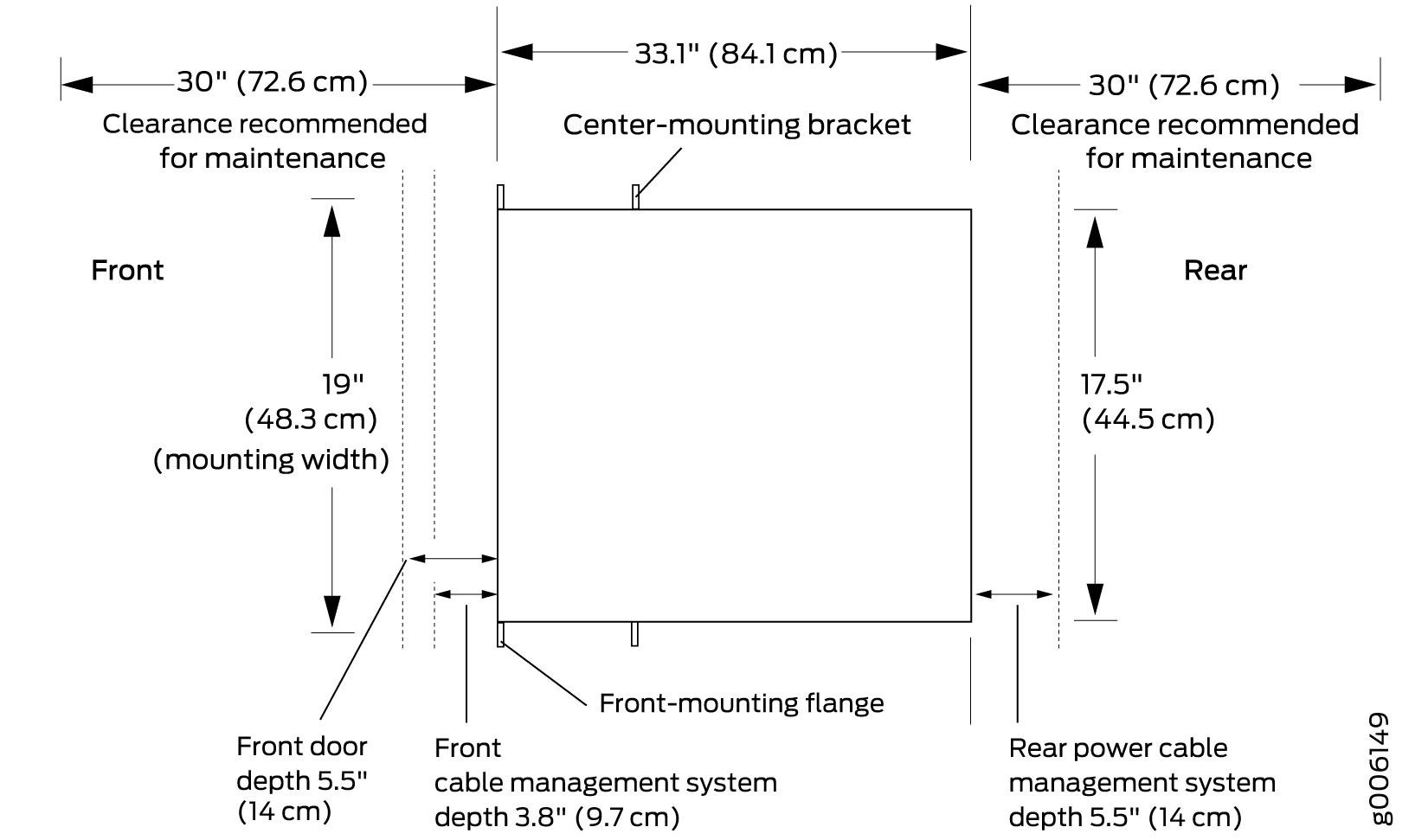
PTX5000 Clearance Requirements for Airflow and Hardware Maintenance
When planning the installation site, allow sufficient clearance around the rack (see Figure 3):
For the cooling system to function properly, the airflow around the chassis must be unrestricted.
Note:If you mount the chassis in a cabinet, be sure that ventilation is sufficient to prevent overheating.
For service personnel to remove and install hardware components, there must be adequate space at the front and back of the chassis. At least 24 in. (61.0 cm) are required both in front of and behind the PTX5000. NEBS GR-63 recommends that you allow at least 30 in. (72.6 cm) behind the rack.
Additional clearance is required to accommodate the depth of the following components:
Front cable management system—3.8 in. (9.7 cm) additional depth in the front of the chassis.
Front door—5.5 in. (14 cm) additional depth in the front of the chassis.
Rear cable management system—5.5 in. (14 cm) additional depth in the rear of the chassis.
See Also
PTX5000 Physical Specifications
Table 5 lists the physical specifications for the PTX5000 chassis and components.
Description |
Weight |
Height |
Width |
Depth |
|---|---|---|---|---|
Chassis with midplane, power shelf, and cable management system |
324 lb (147 kg) |
62.5 in. (158.8 cm) |
17.5 in. (44.5 cm) (excluding the mounting flanges or brackets) |
33.1 in. (84.1 cm) (from front-mounting flange to chassis rear) |
Craft interface |
2.6 lb (1.2 kg) |
3.5 in. (8.9 cm) |
17.4 in. (44.3 cm) |
1.4 in. (3.6 cm) |
CCG |
1.8 lb (0.8 kg) |
1.3 in. (3.2 cm) |
5.8 in. (14.6 cm) |
10.7 in. (27.2 cm) |
Horizontal fan tray |
FAN-PTX-H: 16.3 lb (7.4 kg) |
2.2 in. (5.6 cm) |
14.7 in. (37.3 cm) |
21.2 in. (53.8 cm) |
FAN3-PTX-H: 19.8 lb (9 kg) |
||||
Vertical fan tray (including the vertical air filter tray and air filter) |
26.8 lb (12.2 kg) |
26.4 in. (67 cm) |
3.4 in. (8.7 cm) |
21.9 in. (55.5 cm) |
Horizontal air filter tray (including the air filter) |
7.1 lb (3.2 kg) |
7.4 in. (18.7 cm) |
14 in. (35.6 cm) |
18.6 in. (47.2 cm) |
Vertical air filter tray (including the air filter) |
7.6 lb (3.5 kg) |
26.4 in. (67 cm) |
3.4 in. (8.7 cm) |
11.3 in. (28.6 cm) |
Control Board |
CB-PTX: 10 lb (4.5 kg) |
3.4 in. (8.5 cm) |
17.1 in (43.4 cm) |
11.7 in (29.8 cm) |
CB2-PTX: 10 lb (4.5 kg) |
3.4 in. (8.5 cm) |
17.1 in (43.4 cm) |
11.7 in (29.8 cm) |
|
Routing Engine |
RE-DUO-C2600-16G: 2.8 lb (1.3 kg) |
1.7 in. (4.4 cm) |
10.3 in. (26.2 cm) |
6.9 in. (17.5 cm) |
RE-PTX-X8-64G: 2.6 lb (1.2 kg) |
1.6 in (4.1 cm) |
10.3 in (26.2 cm) |
6.9 in (17.5 cm) |
|
FPC |
FPC-PTX-P1-A: 24.5 lb (11.1 kg) |
25.2 in. (64 cm) |
1.7 in. (4.2 cm) |
21.9 in. (55.7 cm) |
FPC2-PTX-P1A: 38.5 lb (17.5 kg) |
||||
FPC3-PTX-U2: 34 lb (15.4 kg) |
24.4 in. (62 cm) |
1.7 in. (4.2 cm) |
21.9 in. (55.7 cm) |
|
FPC3-PTX-U3: 37 lb (16.8 kg) |
24.4 in. (62 cm) |
1.7 in. (4.2 cm) |
21.9 in. (55.7 cm) |
|
PIC |
P1-PTX-24-10GE-SFPP: 3.7 lb (1.7 kg) |
11.1 in. (28.2 cm) |
1.7 in. (4.3 cm) |
7.8 in. (19.8 cm) |
P1-PTX-24-10G-W-SFPP: 2.5 lb (1.1 kg) |
||||
P1-PTX-2-40GE-CFP: 3.5 lb (1.6 kg) |
||||
P2-10G-40G-QSFPP: 4.3 lb (2 kg) |
||||
P3-15-U-QSFP28: 4 lb (1.8 kg) |
||||
P3-24-U-QSFP28: 4.3 lb (2 kg) |
||||
P1-PTX-2-100GE-CFP: 3.5 lb (1.6 kg) |
||||
P2-100GE-CFP2: 3.9 lb (1.8 kg) |
||||
P2-100GE-OTN: 4.4 lb (2 kg) |
||||
P1-PTX-2-100G-WDM: 5.5 lb (2.5 kg) |
||||
AC PDU |
PDU-PTX-AC-D: 51.2 lb (23.2 kg) |
18.5 in. (46.9 cm) |
7.5 in. (19.1 cm) |
17.7 in. (45 cm) |
PDU-PTX-AC-W: 51.2 lb (23.2 kg) |
||||
High Capacity AC PDU |
PDU2-PTX-AC-D: 63.3 lb (28.7 kg) |
18.5 in. (46.9 cm) |
7.5 in. (19.1 cm) |
17.7 in. (45 cm) |
PDU2-PTX-AC-W: 63.3 lb (28.7 kg) |
||||
PDU2-PTX-AC-SP: 60.5 lb (27.4 kg) |
||||
AC PSM |
10.5 lb (4.8 kg) |
5.7 in. (14.5 cm) |
3.4 in. (8.7 cm) |
14.1 in. (35.9 cm) |
DC PDU |
PDU-PTX-DC-120: 60 lb (27.2 kg) |
18.5 in. (46.9 cm) |
7.5 in. (19.1 cm) |
17.7 in. (45 cm) |
PDU-PTX-DC-60: 60 lb (27.2 kg) |
||||
DC PSM |
10.6 lb (4.8 kg) |
5.7 in. (14.5 cm) |
3.4 in. (8.7 cm) |
14.1 in. (35.9 cm) |
High Capacity DC PDU |
64.5 lb (29.3 kg) |
18.5 in. (46.9 cm) |
7.5 in. (19.1 cm) |
17.7 in. (45 cm) |
High Capacity DC PSM |
10.1 lb (4.6 kg) |
5.7 in. (14.5 cm) |
1.7 in. (4.3 cm) |
21.7 in. (55.2 cm) |
SIB |
SIB-I-PTX5008: 6 lb (2.7 kg) |
1.7 in. (4.2 cm) |
15.9 in. (40.3 cm) |
10.7 in. (27.2 cm) |
SIB2-I-PTX5K: 7 lb (3.2 kg) |
||||
SIB3-I-PTX5K: 10.4 lb (4.7 kg) |
See Also
Site Electrical Wiring Guidelines
Table 6 describes the factors you must consider while planning the electrical wiring at your site.
You must provide a properly grounded and shielded environment and use electrical surge-suppression devices.
Avertissement Vous devez établir un environnement protégé et convenablement mis à la terre et utiliser des dispositifs de parasurtension.
Site Wiring Factor |
Guidelines |
|---|---|
Signaling limitations |
If your site experiences any of the following problems, consult experts in electrical surge suppression and shielding:
|
Radio frequency interference |
To reduce or eliminate RFI from your site wiring, do the following:
|
Electromagnetic compatibility |
If your site is susceptible to problems with electromagnetic compatibility (EMC), particularly from lightning or radio transmitters, seek expert advice. Strong sources of electromagnetic interference (EMI) can cause:
|
Rack Requirements for the PTX5000
- Rack Size and Strength
- Spacing of Mounting Bracket and Flange Holes
- Connection to Building Structure
Rack Size and Strength
The PTX5000 is designed for installation in a rack that complies with either of the following standards:
A 19-in. rack as defined in Cabinets, Racks, Panels, and Associated Equipment (document number EIA-310-D) published by the Electronics Components Industry Association (http://www.ecianow.org/).
A 600-mm rack as defined in the four-part Equipment Engineering (EE); European telecommunications standard for equipment practice (document numbers ETS 300 119-1 through 119-4) published by the European Telecommunications Standards Institute (http://www.etsi.org). The horizontal spacing between the rails in a rack that complies with this standard is usually wider than the mounting brackets, which measure 19 in. (48.3 cm) from outer edge to outer edge. Use approved wing devices to narrow the opening between the rails as required.
A 23-in. rack using appropriate 23-in. to 19-in. rack adapters and an appropriate installation shelf which supports the chassis at the correct vertical position to properly line up the rack mount holes. Juniper Networks does not supply this hardware, but consideration for the size and weight of the chassis is important for a safe installation. Juniper recommends the use of single-sided panel adapters of at least 10 U in height, using as many as needed to fully overlap the chassis rack mount bracket for this type of installation.
The rack rails must be spaced widely enough to accommodate the chassis's external dimensions: 62.5 in. (158.8 cm) high, 33.1 in. (84.1 cm) deep, and 17.5 in. (44.5 cm) wide. The outer edges of the mounting brackets extend the width to 19 in. (48.3 cm). The front cable management system adds 3.8 in. (9.7 cm) to the depth. If the front door is used, this adds 5.5 in. (14 cm) to the depth of the chassis. The rear cable management system adds 5.5 in. (14 cm) to the depth of the chassis.
The spacing of rails and adjacent racks must also allow for the clearances around the chassis and rack that are specified in PTX5000 Clearance Requirements for Airflow and Hardware Maintenance.
For instructions about installing the mounting hardware, see Installing the PTX5000 Mounting Hardware for a Four-Post Rack or Cabinet.
The chassis height of 62.5 in. (158.8 cm) high is approximately 35.7 U. A U is the standard rack unit defined in Cabinets, Racks, Panels, and Associated Equipment (document number EIA-310-D) published by the Electronics Industry Association. You can install one chassis in a rack that has at least 35.7 U of usable vertical space.
The rack must be strong enough to support the weight of the fully configured PTX5000, up to about 1,200 lb (544.3 kg).
In an open-frame rack, center-mounting is required because the more even distribution of weight provides greater stability. For center-mounting, you use the mounting brackets attached to the center of the chassis for rack mounting.
Spacing of Mounting Bracket and Flange Holes
The holes in the mounting brackets and front-mount flanges used to attach the chassis to a rack are spaced at 3 U (5.25 in. or 13.3 cm). The PTX5000 can be mounted in any rack that provides holes spaced at those distances.
Connection to Building Structure
Always secure the rack to the structure of the building. If your geographical area is subject to earthquakes, bolt the rack to the floor. For maximum stability, also secure the rack to ceiling brackets.