ON THIS PAGE
Maintaining the PTX5000 Cooling System
Maintaining the PTX5000 Fan Trays
Purpose
For optimum cooling, verify the condition of the fan trays.
Action
On a regular basis:
Check the fan tray LEDs on the craft interface. During normal operation, the LEDs are lit green to indicate that the cooling system is functioning normally.
Place your hand near the exhaust vents at the rear of the chassis to determine whether the fans are pushing air out of the chassis.
Zone 0: The air exhausts from the left side of the SIBs.
Zone 1: The exhaust vent is located at the upper rear of the chassis.
Power system: The air exhausts from the power supply modules (PSMs).
Monitor the status of the fans. During normal operation, the fans in each fan tray are functioning at less than full speed.
The fan trays each contain multiple fans that work in unison to cool the router’s components. If one fan fails, the host subsystem adjusts the speed of the remaining fans to maintain proper cooling. A red alarm is triggered when a fan fails, and a yellow alarm is triggered when a fan tray is removed.
To display the status of the fans, issue the
show chassis
fan
command.
Replacing a PTX5000 Horizontal Fan Tray
Removing a PTX5000 Horizontal Fan Tray
The upper horizontal fan tray is located below the craft interface, and the lower horizontal fan tray is located above the horizontal air filter. Each horizontal fan tray weighs about 16.3 lb (7.4 kg).
After removing a fan tray, make sure to immediately insert the new fan tray. Do not remove both horizontal fan trays at the same time. Removing both front fan trays might cause the PTX5000 to shut down.
To remove a horizontal fan tray (see Figure 1 and Figure 2):
Installing a PTX5000 Horizontal Fan Tray
- Attach an electrostatic discharge (ESD) grounding strap to your bare wrist, and connect the strap to one of the ESD points on the chassis.
- Grasp the fan tray by its handle and insert it straight into the chassis.
- Tighten the captive screw on the left side of the fan tray faceplate to secure it in the chassis, using a number 2 Phillips (+) screwdriver.

Replacing a PTX5000 Vertical Fan Tray
Removing a PTX5000 Vertical Fan Tray
The vertical fan tray is located in the front of the chassis. The vertical fan tray contains fourteen fans and weighs about 26.8 lb (12.2 kg).
To maintain proper cooling, do not operate the PTX5000 with the fan trays removed for more than one minute.
To remove the vertical fan tray (see Figure 5):
Installing a PTX5000 Vertical Fan Tray
To install a replacement vertical fan tray (see Figure 6):
- Attach an electrostatic discharge (ESD) grounding strap to your bare wrist, and connect the strap to one of the ESD points on the chassis.
- Grasp the fan tray handle and insert it straight into the chassis.
- Tighten the captive screw on the bottom of the fan tray faceplate to secure it in the chassis, using a number 2 Phillips (+) screwdriver.
Maintaining the PTX5000 Air Filters
Purpose
For optimum cooling, verify the condition of the air filters.
Action
On a regular basis:
Check the air filters for dust and debris.
As a general guideline, we recommended that you replace the filter elements every 6 months for routers operating in a typical environment. The filter elements degrade over time, and replacement intervals will vary by operating environment.
The shelf life of polyurethane filter varies from two years to five years depending on the storage conditions. Store in a cool, dry, and dark environment. Wrap the media in plastic and store in an environment with relative humidity between 40%- 80% and temperature between 40°F (4° C) to 90°F (32° C). Note that if the material flakes, or becomes brittle when rubbed or deformed, it is no longer usable.
Always keep the air filters in place while the PTX5000 is operating. The fans are very powerful, and could pull small bits of wire or other materials into the PTX5000 through the unfiltered air intake. This could damage the router’s components.
Replacing a PTX5000 Horizontal Air Filter
Removing a PTX5000 Horizontal Air Filter
The horizontal air filter is located below the lower horizontal fan tray. The horizontal air filter weighs approximately 7.1 lb (3.2 kg).
To remove the horizontal air filter:
- Attach an electrostatic discharge (ESD) grounding strap to your bare wrist, and connect the strap to one of the ESD points on the chassis.
- Loosen the two captive screws on the horizontal air filter tray.
- Grasp the head of the loosened screws, and pull to remove the air filter tray (see Figure 7).
- Locate the two areas, near each rear corner, where the air filter tray is exposed. Using these air filter tray frame access areas, slide the air filter toward the air filter tray faceplate, and pull up on the air filter to release the rear edge of the air filter from the air filter tray (see Figure 8).
- Remove air filter from the air filter tray.
- Discard the air filter.
Installing a PTX5000 Horizontal Air Filter
To install the horizontal air filter:
Replacing a PTX5000 Vertical Air Filter
Removing a PTX5000 Vertical Air Filter
The vertical air filter is located with the vertical fan tray fan tray 0. The vertical air filter weighs approximately 7.6 lb (3.5 kg).
To remove the vertical air filter:
- Attach an electrostatic discharge (ESD) grounding strap to your bare wrist, and connect the strap to one of the ESD points on the chassis.
- Loosen the two captive screws on the vertical air filter tray.
- Grasp the head of the loosened screws, and pull to remove the air filter tray (see Figure 11).
- Locate the two areas near each rear corner, where the air filter tray is exposed. Using these air filter tray frame access areas, slide the air filter toward the air filter tray faceplate, and pull up on the air filter to release the rear edge of the air filter from the air filter tray (see Figure 12).
- Remove the air filter from the air filter tray.
- Discard the air filter.
Installing a PTX5000 Vertical Air Filter
To install the vertical air filter:
Replacing a PTX5000 Power Supply Module Air Filter
- Removing a PTX5000 Power Supply Module Air Filter
- Installing a PTX5000 Power Supply Module Air Filter
Removing a PTX5000 Power Supply Module Air Filter
The PSM air filter is located inside the PSM door.
To remove the PSM air filter (see Figure 15):
- Attach an electrostatic discharge (ESD) grounding strap to your bare wrist, and connect the strap to one of the ESD points on the chassis.
- Loosen the captive screws on the PSM door, and open the door.
- Inside the PSM door, locate the air filter retaining bracket at the top of the door. Using a number 2 Phillips (+) screwdriver, remove the 2 screws from the air filter retaining bracket, and remove the bracket.
- Remove the air filter.
- Discard the air filter.
1 — Air filter retaining bracket | 2 — Air filter |
Installing a PTX5000 Power Supply Module Air Filter
To install the PSM air filter (see Figure 16):
- Attach an electrostatic discharge (ESD) grounding strap to your bare wrist, and connect the strap to one of the ESD points on the chassis.
- Locate markings on the side of the frame indicating airflow direction.
- Install the air filter into the door. Note that the correct orientation for airflow direction is through the perforated door and into the PSMs.
- Engage the edge nearest the perforated faceplate under the front flange, and slide the air filter further toward the faceplate.
- Reinstall the air filter retainer bracket and secure with two screws.
- Tighten the captive screws to secure the PSM door.
1 — Air filter | 2 — Air filter retaining bracket |
Replacing a PTX Series PIC Air Filter
Removing a PTX Series PIC Air Filter
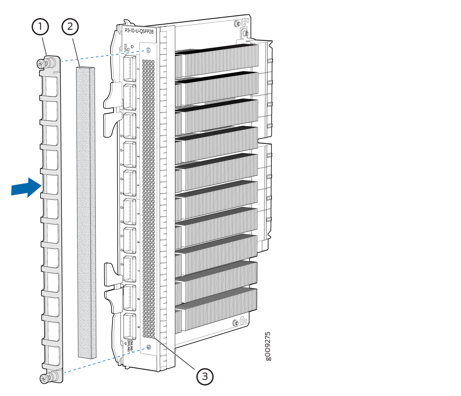
The 10-port 10-Gigabit Ethernet/40-Gigabit Ethernet/100-Gigabit Ethernet PIC with QSFP28 (P3-10-U-QSFP28) has air vents on the PIC faceplate, and has a field-replaceable air filter cover over the air vents.
To remove the PIC air filter (see Figure 17):
- Loosen the thumbscrews that secure the air filter cover to the PIC faceplate.
- Pull to remove the air filter cover and air filter.
- Remove the air filter from the air filter cover.
- Discard the air filter.
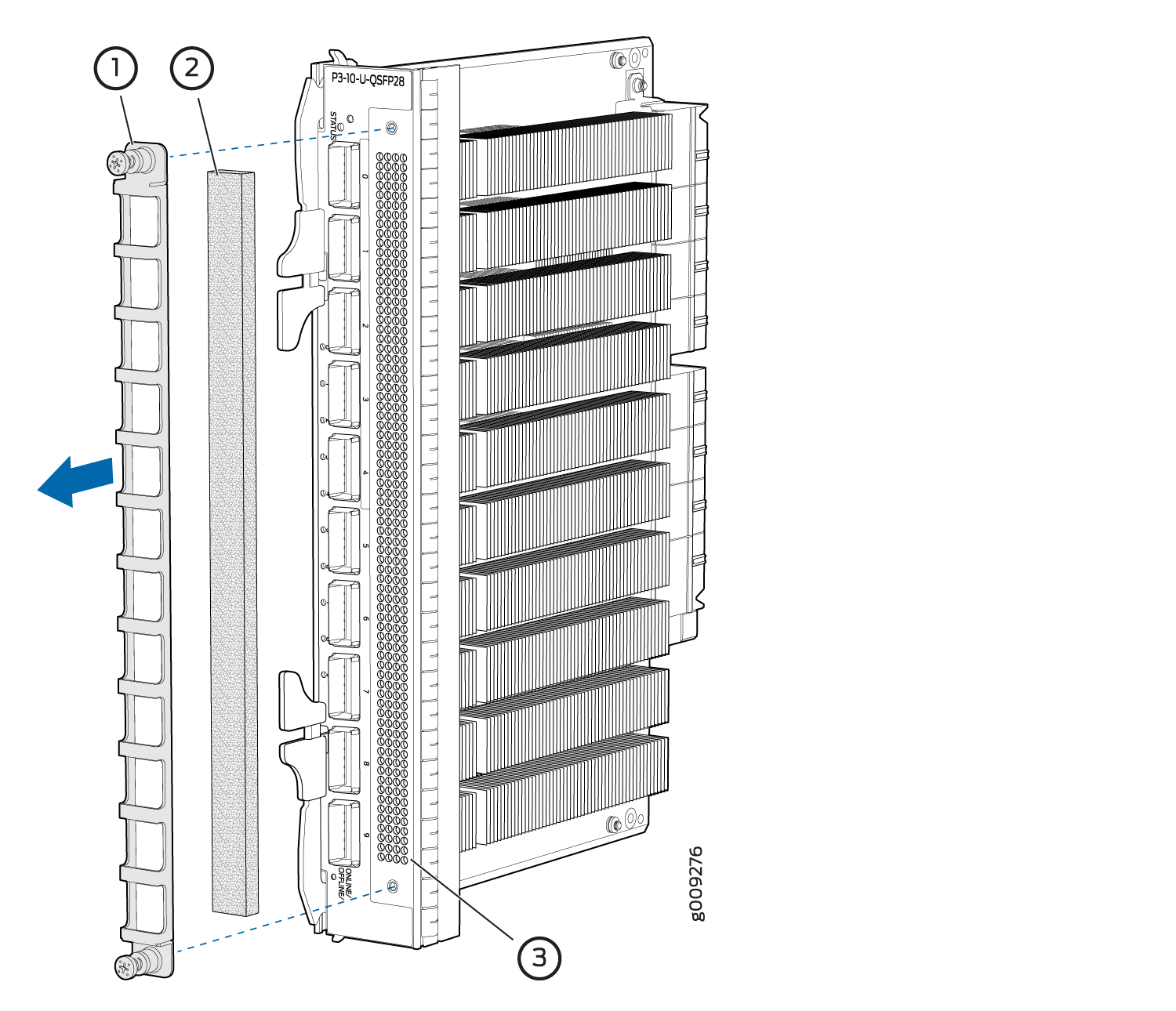
1 — Air filter cover | 3 — Air vent |
2 — Air filter |
Installing a PTX Series PIC Air Filter
To install the PIC air filter (see Figure 18):
- Place the air filter in the air filter cover.
- Reinstall the air filter cover on to the PIC faceplate.
- Tighten the thumbscrews that secure the air filter cover to the PIC faceplate.
1 — Air filter cover | 3 — Air vent |
2 — Air filter |