Unpacking the PTX5000
Overview of Unpacking the PTX5000
To unpack the PTX5000:
See Also
Tools and Parts Required to Unpack the PTX5000
Gather the tools required to unpack the PTX5000:
Phillips (+) screwdriver, number 2
1/2-in. or 13-mm open-end or socket wrench to remove bracket bolts from the shipping pallet
Blank panels to cover any slots not occupied by a component
Unpacking the PTX5000
The PTX5000 is shipped in a wooden crate. A wooden pallet forms the base of the crate. The chassis is bolted to this pallet. Quick Start installation instructions and a cardboard accessory box are also included in the shipping crate.
The shipping crate measures:
73.3 in (186.2 cm)high
33.0 in (83.8 cm) wide
51.5 in (130.9 cm) deep
The total weight of the crate containing the PTX5000 and accessories can range up to 1,300 lb (589.7 kg).
The PTX5000 is maximally protected inside the shipping crate. Do not unpack it until you are ready to begin installation.
To unpack the PTX5000 (see Figure 1):
- Move the shipping crate to a staging area as close to the installation site as possible, where you have enough room to remove the components from the chassis. While the chassis is bolted to the pallet, you can use a forklift or pallet jack to move it.
- Position the shipping crate with the arrows pointing up.
- Open all the latches on the shipping crate.
- Remove the front door of the shipping crate cover and set it aside.
- Slide the remainder of the shipping crate cover off the pallet.
- Remove the foam covering the top of the PTX5000.
- Remove the accessory box and the Quick Start documentation.
- Verify the parts received against the lists in Verifying the PTX5000 Parts Received.
- Remove the vapor corrosion inhibitor (VCI) packs attached to the pallet, being careful not to break the VCI packs open.
- To remove the brackets holding the chassis on the pallet, use a 1/2-in. socket wrench and a number 2 Phillips (+) screwdriver to remove the bolts and screws from the brackets.
- Store the brackets and bolts inside the accessory box.
- Save the shipping crate cover, pallet, and packing materials in case you need to move or ship the PTX5000 at a later time.
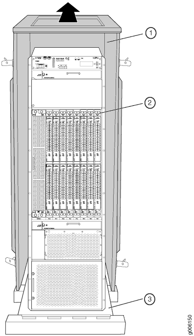
1 — Shipping crate cover | 3 — Shipping crate base |
2 — Chassis |
Verifying the PTX5000 Parts Received
A packing list is included in each shipment. The packing list specifies the part numbers and descriptions of each part in your order.
To verify that you have received all parts:
Component |
Quantity |
|---|---|
Chassis, including midplane and craft interface |
1 |
FPCs |
Up to 8 |
PICs |
Up to 2 for each FPC |
SIBs |
9 |
Routing Engines |
1 or 2 |
Control Boards |
1 or 2 (one for each Routing Engine) |
Centralized Clock Generators (CCGs) |
1 or 2 |
Power distribution unit (PDU) |
2 |
Power supply modules (PSMs) |
Normal-capacity PDU: Up to 4 PSMs for each PDU High-capacity PDU: Up to 8 PSMs for each PDU |
Horizontal fan trays |
2 |
Vertical fan tray |
1 |
Quick start installation |
1 |
Open-frame mounting shelf |
1 |
Four-post mounting shelf |
1 |
Rear support bracket—Required only for mounting a four-post rack or cabinet |
1 |
Blank panels for slots without components installed |
One blank panel for each slot not occupied by a component |
Part |
Quantity |
|---|---|
Screws to mount chassis, Phillips, 12-24 x 1/2 in. , self-tapping |
42 |
Split washers for the grounding cable |
3 |
Screws to fasten grounding cable to chassis, Phillips, 1/4-20 x 3/8 |
3 |
DC cable lugs and power cable management system |
Depending on your configuration, the following parts are included;
Note:
Spare cable lugs are included in the accessory kit. Use one of the included spare cable lugs to connect the PTX5000 to earth ground. |
Connectors for alarm relay cables, Terminal Block Plug, 3 Pole, 5.08 mm spacing, 12 A |
3 |
End User License Agreement (EULA) |
1 |
ROHS and warranty card |
1 |
15-ft Ethernet cable to connect the Routing Engine to a management device (RJ-45 connectors, 4-pair stranded UTP, Category 5E) |
1 |
7-ft serial cable to connect the Routing Engine to a management console (DB9 to RJ-45 adapter, straight through) |
1 |
ESD wrist strap with cable |
1 |