
Fast Track to Rack Installation and Power
This procedure guides you through the simplest steps to install your PTX12008 Router in a rack and connect it to AC/HVAC/HVDC power. Have more complex installation needs? See Install the PTX12008.

Install the PTX12008 in a Rack
You can install the PTX12008 in a 19-inch wide four-post rack or in a cabinet that has a 19-inch wide four-post rack. We’ll walk you through the steps to install a router in a four-post rack using the PTX12K-RMK rack mount kit and connect it to AC/HVAC/HVDC power.
Before you install the router, review the following:
-
Ensure that you have taken the necessary precautions to prevent electrostatic discharge (ESD) damage. See Prevention of Electrostatic Discharge Damage.
-
Ensure that you know how to handle and store the Flexible PIC Concentrators (FPCs).
-
Ensure that the router has sufficient power to power on the FPCs while maintaining its n+1 power redundancy. To determine whether the router has enough power available for the FPCs, see the Power Calculator.
-
Have three persons available—two persons to push the router onto the mounting tray and a third person to align the router to the mounting tray.
-
Have the following parts and tools available:
-
The PTX12K-RMK rack mount kit—provided
-
50 screws appropriate for your rack—not provided
-
A mechanical lift to mount the router—not provided
-
A grounding cable—not provided. The grounding cable must be of the same size (4 AWG) or heavier than the input wire of each power supply module (PSM).
-
An ESD grounding strap—not provided
-
A Phillips (+) screwdriver, number 2—not provided
-
A Phillips (+) screwdriver, number 3—not provided
-
Mount the PTX12008 Router
Wrap and fasten one end of the ESD grounding strap around your bare wrist, and connect the other end to a site ESD point.
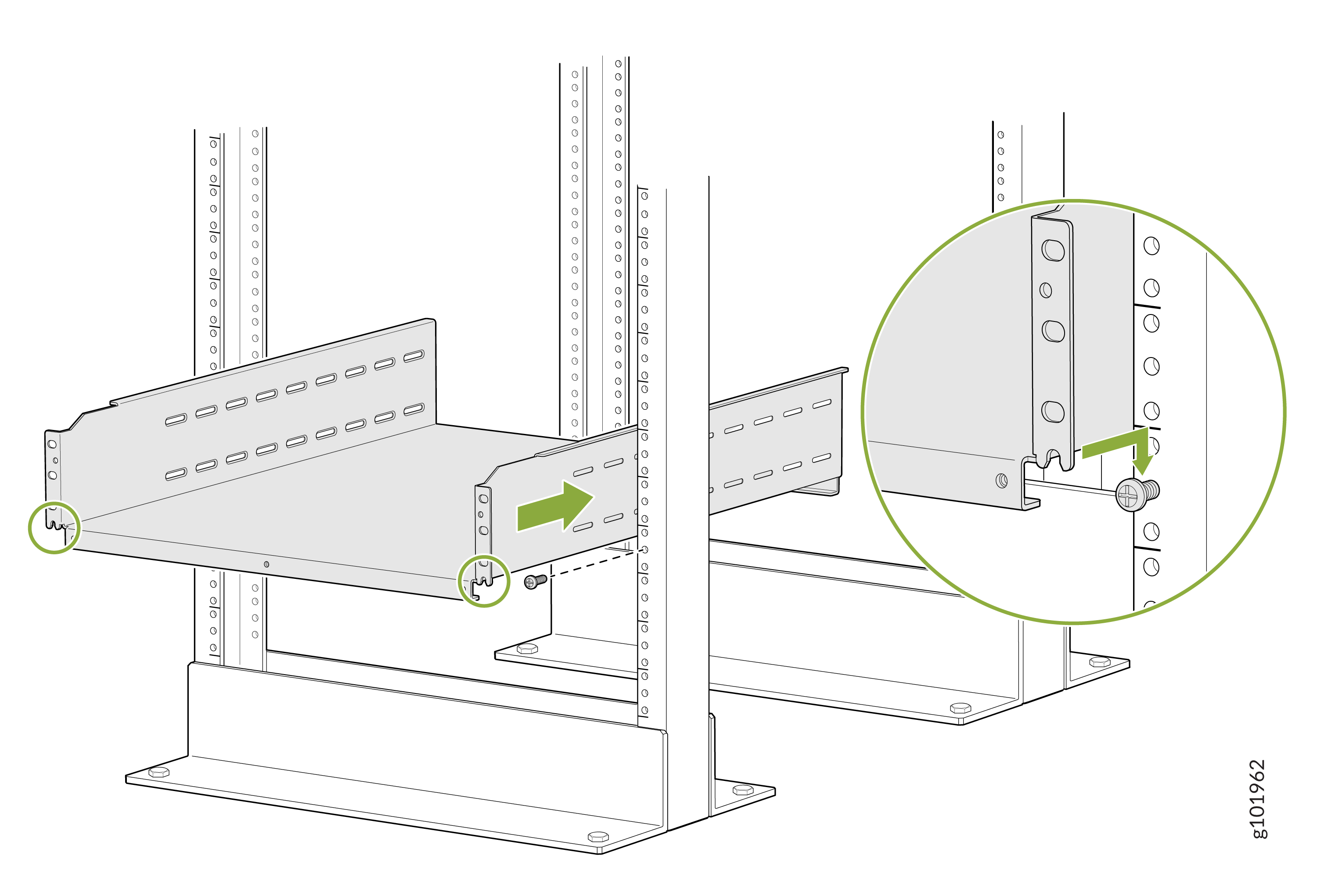
On the front of each front rack post, insert a screw appropriate for your rack in the screw slot in the center of a rack unit, partially. Rest the bottom slot of the mounting tray on the screws. The mounting tray extends toward the center of the rack. Tighten the screws by using a screwdriver.
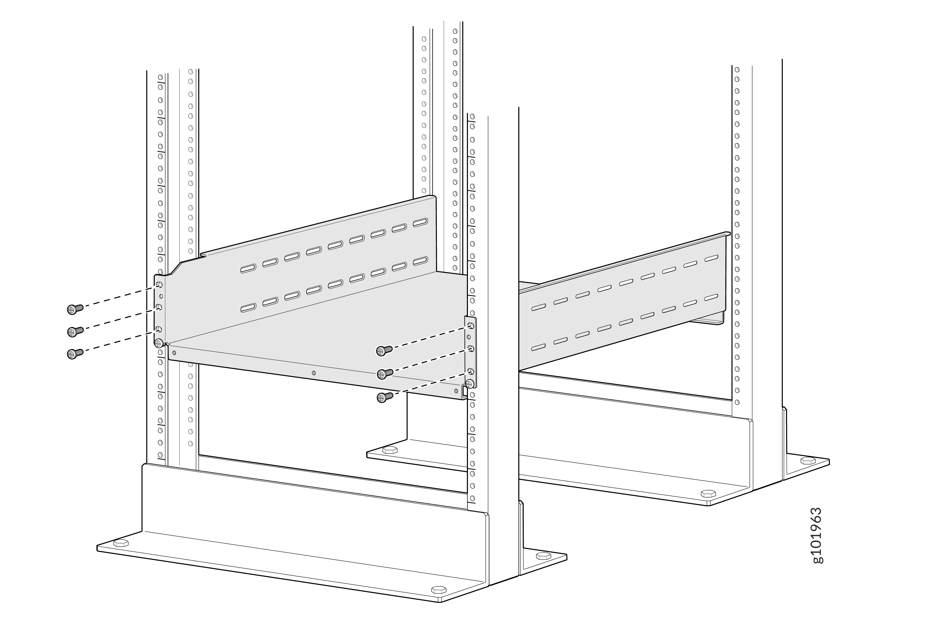
Attach the mounting tray to the front rack posts by using six screws appropriate for your rack and a screwdriver.
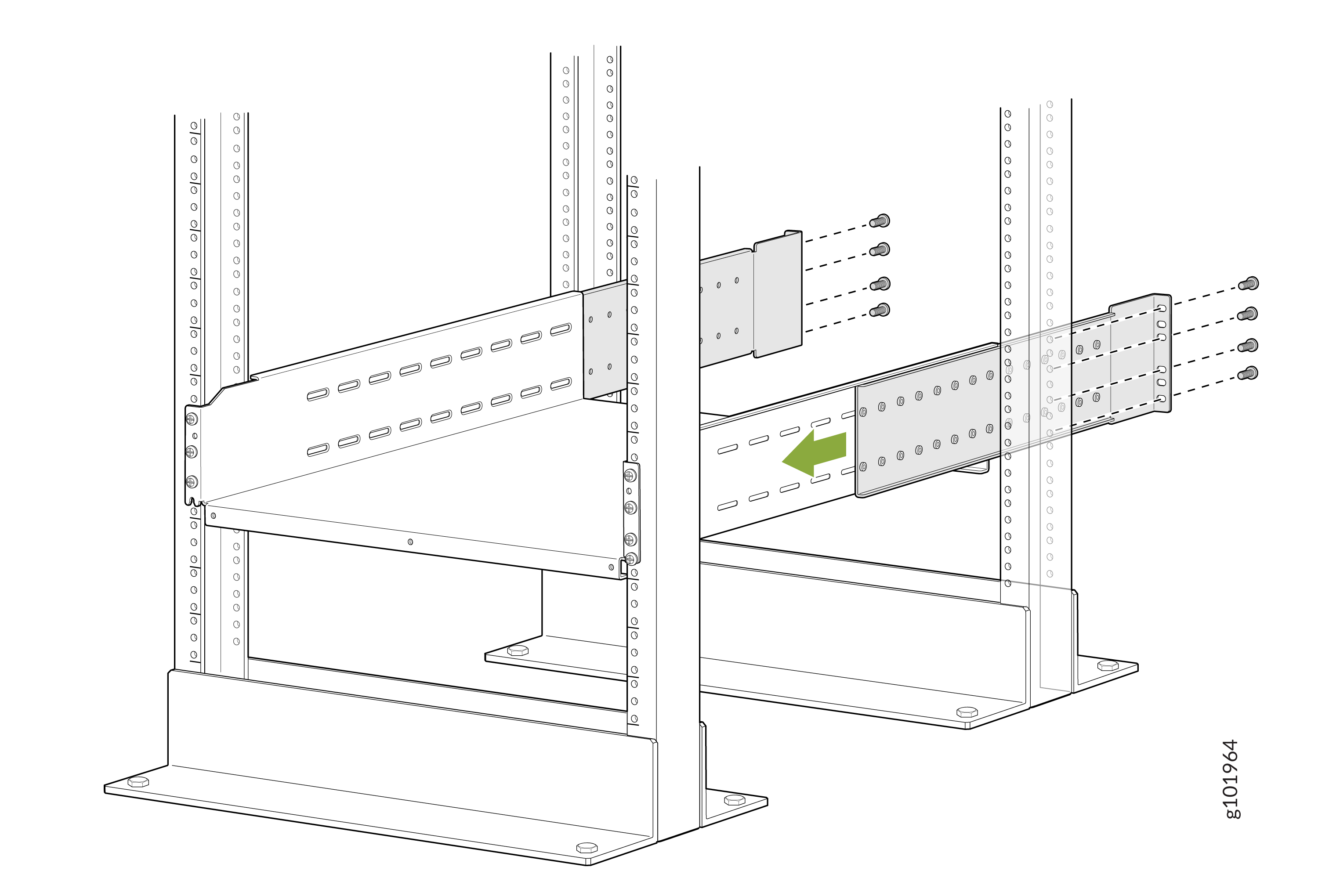
From the rear of the rack, slide the mounting tray brackets into the grooves of the mounting tray. Attach the mounting tray brackets to the rear rack posts by using four rack-mounting screws each appropriate for your rack and a screwdriver.
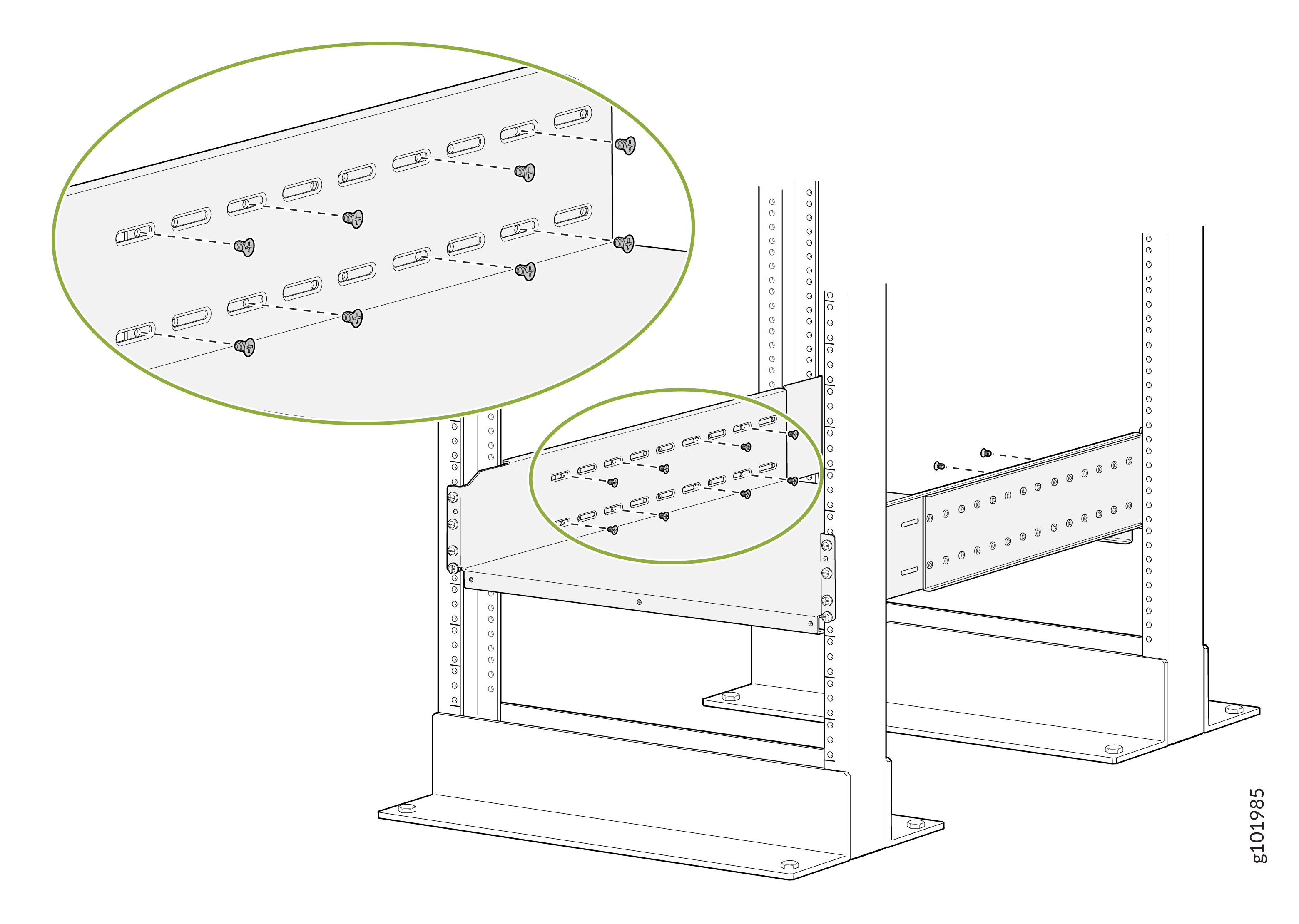
Ensure that the mounting tray is level by verifying that all the screws on one side of the rack align with the screws on the other side of the rack.
Attach the mounting tray brackets to the mounting tray with a minimum of 16 Phillips M4x8mm flat-head screws and a Phillips (+) screwdriver, number 2.
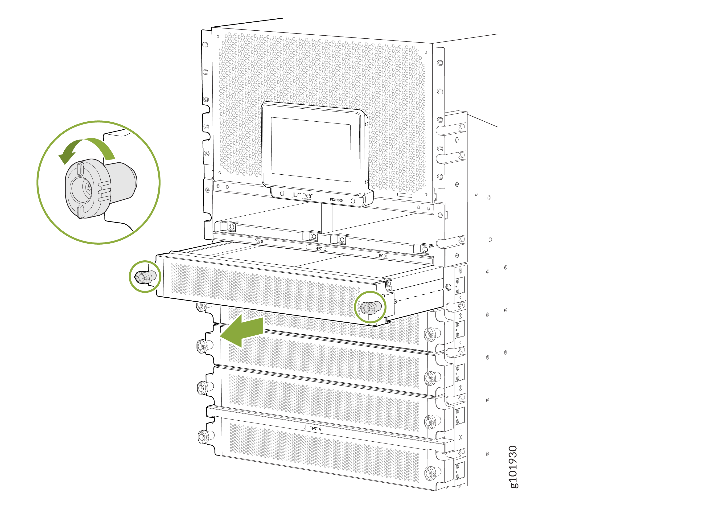
Remove each FPC slot cover from the router by grasping the handles, turning them counterclockwise, and pulling the cover straight out. Store the covers.
 Note: The router weights 275 lb (124.7 kg). Because of the router's size and weight, we strongly recommend that you use a mechanical lift to mount the router.
Load the router onto a lift, making sure it rests securely on the lift platform.
Using the lift, align the chassis in front of the rack and center it in front of the mounting tray.
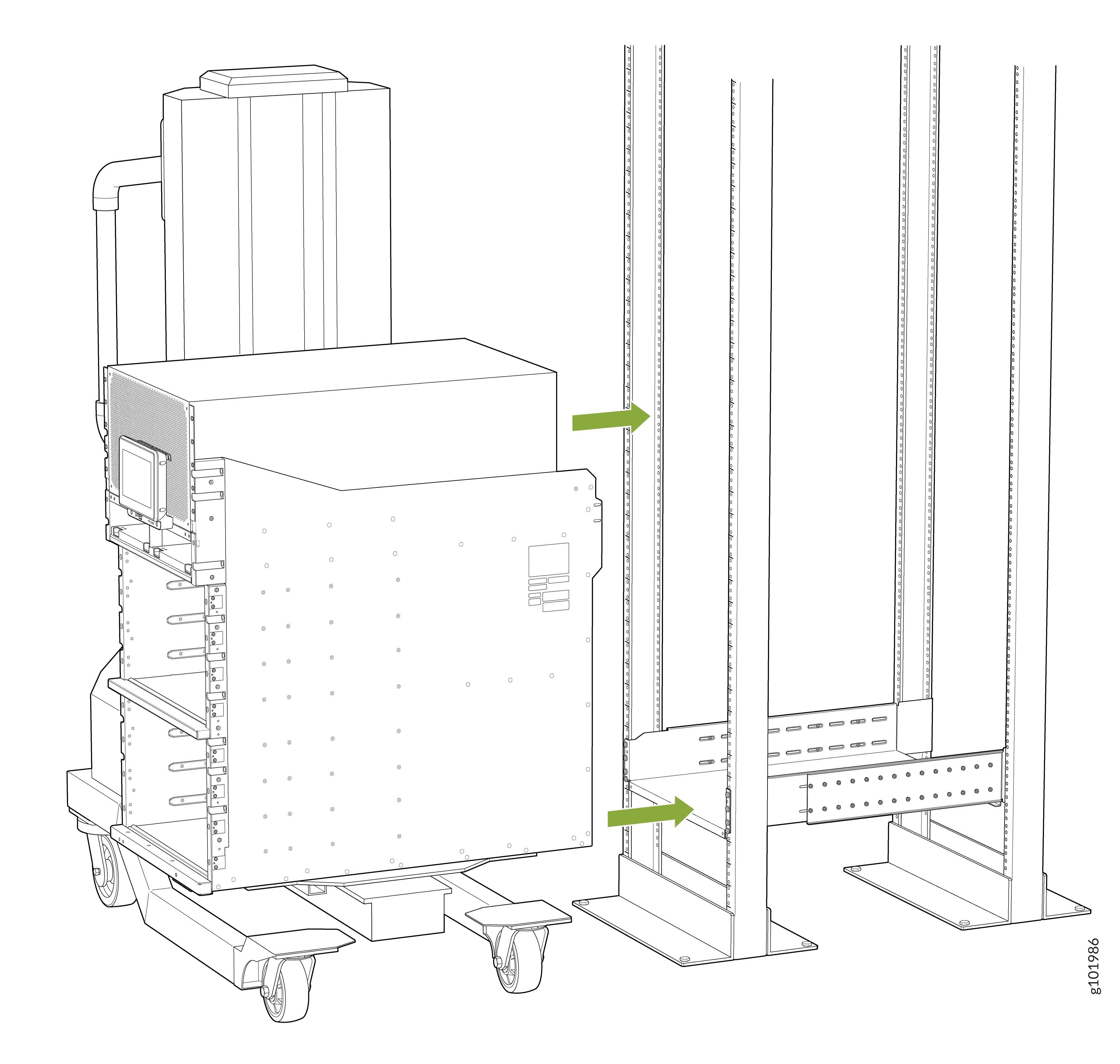
Lift the chassis slightly above the surface of the mounting tray. Position the chassis as close as possible to the mounting tray.
Carefully slide the chassis onto the mounting tray until the chassis flanges contact the rack posts. We recommend that at least two people push the router onto the mounting tray while a third person aligns the router to the mounting tray.
Move the lift away from the rack.
Check the alignment of the router. The rack-mounting screw slots on each side of the rack should line up, and the router should be level.
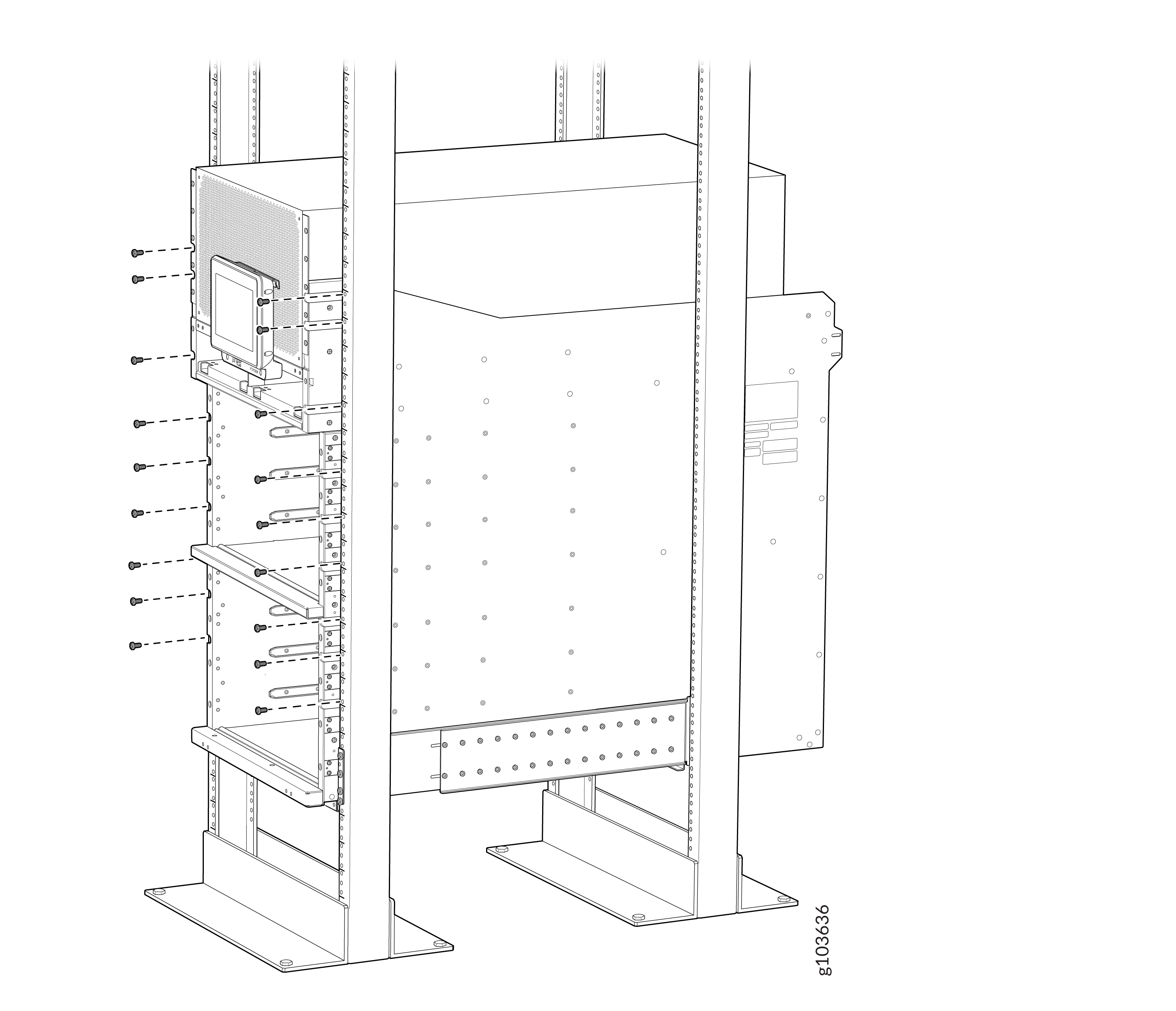
Attach the two chassis flanges to the front posts of the rack by using rack-mounting screws appropriate for your rack and a screwdriver. You must use nine rack-mounting screws for each chassis flange.
Attach the two rear side brackets to the rack by using rack-mounting screws appropriate for your rack and a screwdriver. You must use eight rack-mounting screws for each mounting bracket.
Depending on the location of the rack posts in relation to the chassis, you can attach the rear side brackets in two different orientations. Figure 1 shows the orientation of the brackets when the chassis extends out of the rack posts. Figure 2 shows the orientation of the brackets when the chassis is inside the rack posts.
Figure 1: Attach the Rear Side Brackets to the Rack When the Chassis Extends Out of the Rack Posts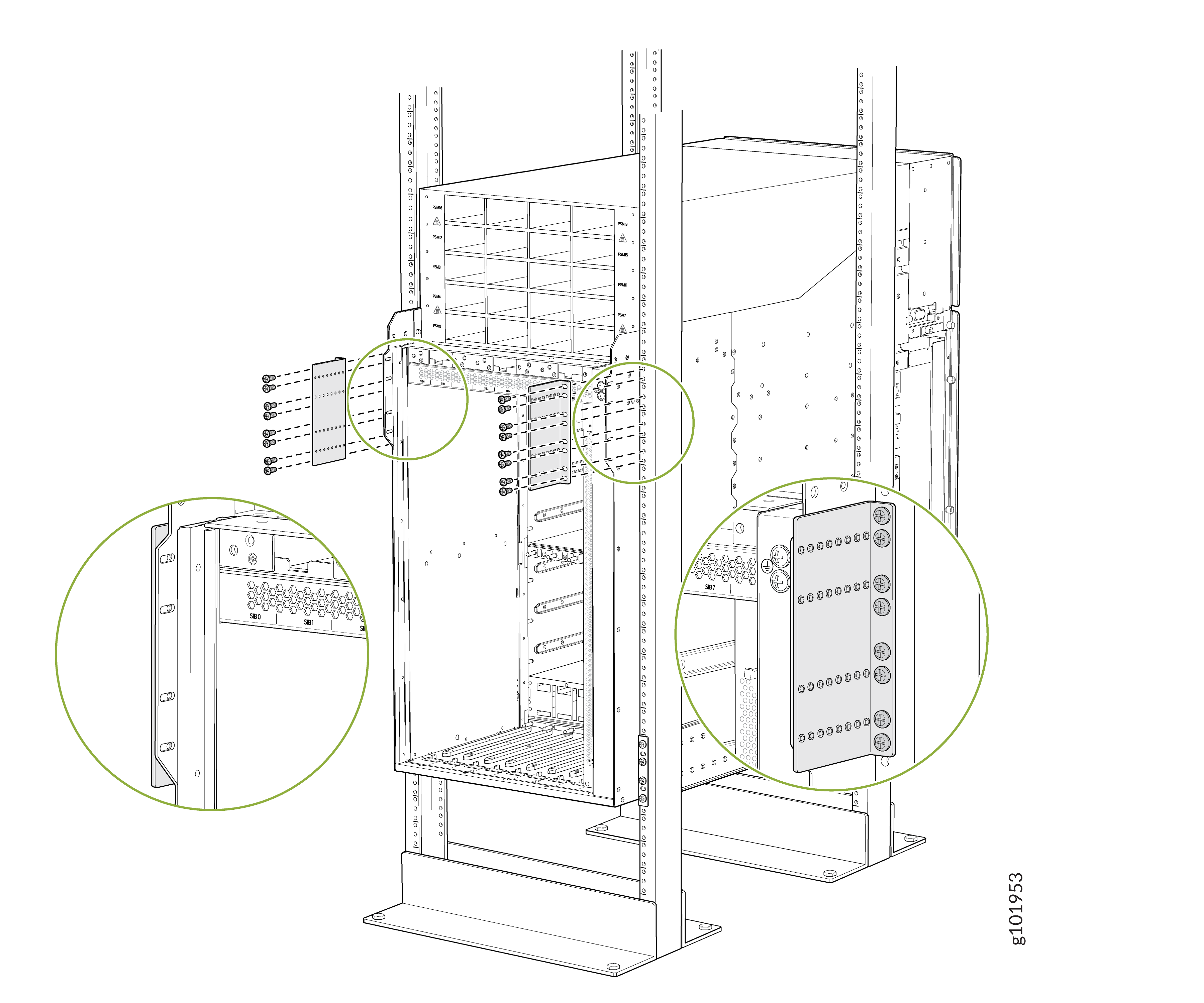 Figure 2: Attach the Rear Side Brackets to the Rack When the Chassis Is Inside the Rack Posts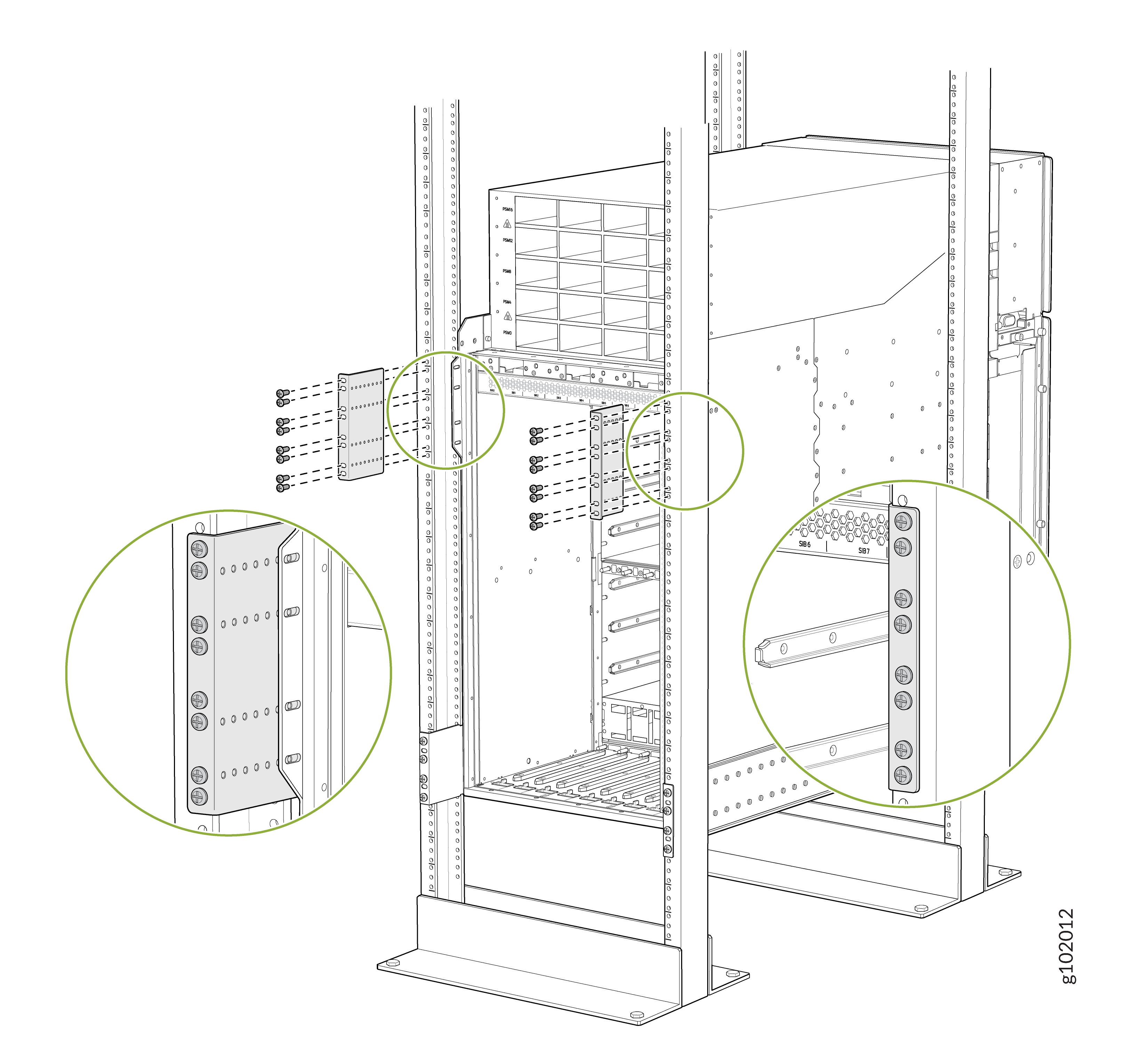
Attach the chassis to each rear side brackets by installing eight rack-mounting screws through each open flange hole and a screw slot on the rack and a screwdriver. Tighten the screws using a Phillips (+) screwdriver, number 2. Apply 18 lb⋅in (2 Nm) of torque to the screws.
Depending on the location of the rack posts in relation to the chassis, you can use the rear brackets in two different orientations. Figure 3 shows the orientation of the brackets when the chassis extends out of the rack posts. Figure 4 shows the orientation of the brackets when the chassis is inside the rack posts.
Figure 3: Attach the Chassis to the Rear Side Brackets When the Chassis Extends Out of the Rack Posts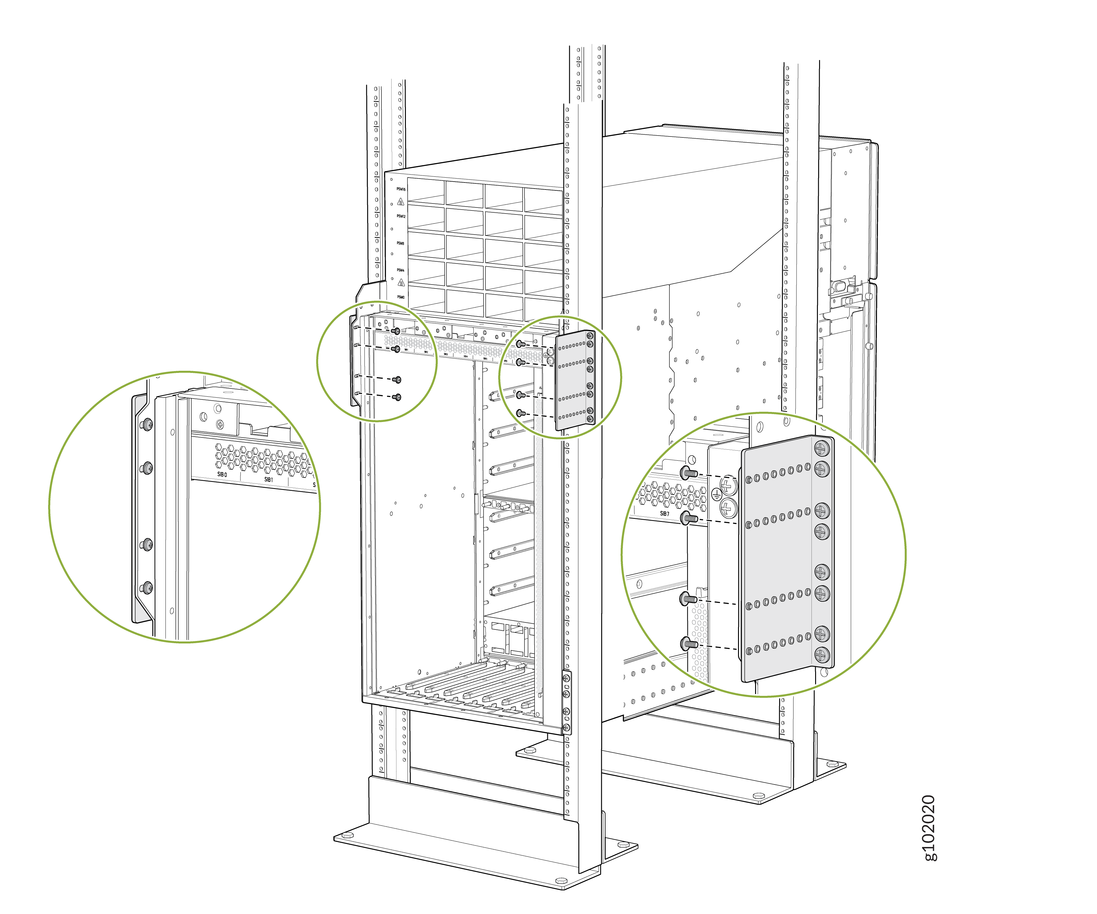 Figure 4: Attach the Chassis to the Rear Side Brackets When the Chassis Is Inside the Rack Posts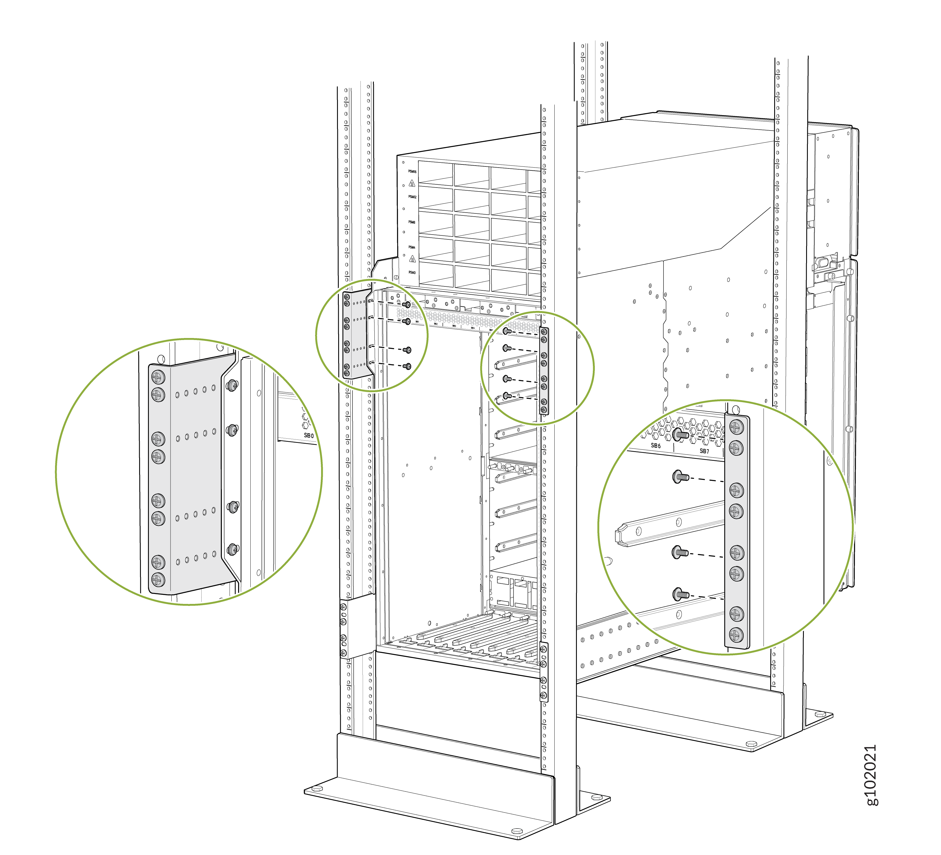
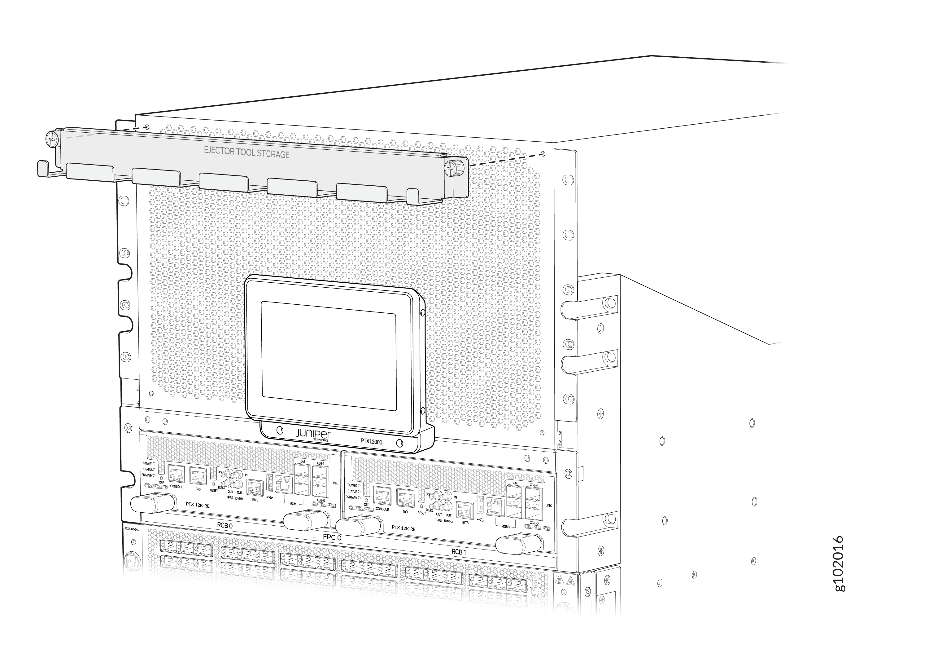
Attach the FPC ejector tools storage tray at the top of the front panel of the router chassis. Use a Phillips (+) screwdriver, number 2 to tighten the screws.
Connect to AC/HVAC/HVDC Power
You must install the PTX12008 in a restricted-access location and ensure that the chassis is always properly grounded. The PTX12008 has a two-hole protective grounding terminal on the upper right corner of the rear panel of the chassis. Under all circumstances, use this grounding terminal to ground the chassis. For AC/HVAC/HVDC-powered systems, you must also use the grounding wire in the power cord along with the two-hole grounding connection. This tested system of using the grounding wire along with the two-hole protective grounding terminal meets or exceeds all applicable EMC regulatory requirements.
Before you connect the protective grounding terminal on the router to an earth ground, ensure that a licensed electrician attaches an appropriate grounding terminal to the grounding cable you supply. Using a grounding cable with an incorrectly attached terminal lug can damage the router.
To connect the PTX12008 to AC/HVAC/HVDC power, you must do the following:
- Ground the PTX12008 Router
- Install the AC/HVAC/HVDC Power Supply Module and Connect the PTX12008 Router to Power
Ground the PTX12008 Router
To ground the PTX12008:
Verify that a licensed electrician has attached the protective grounding terminal lug provided to the grounding cable.
Connect the other end of the grounding cable to a proper earth ground.
Wrap and fasten one end of the ESD grounding strap around your bare wrist and connect the other end of the strap to the ESD point on the rear panel of the chassis.
Figure 5: ESD Point on the Rear Panel of the Chassis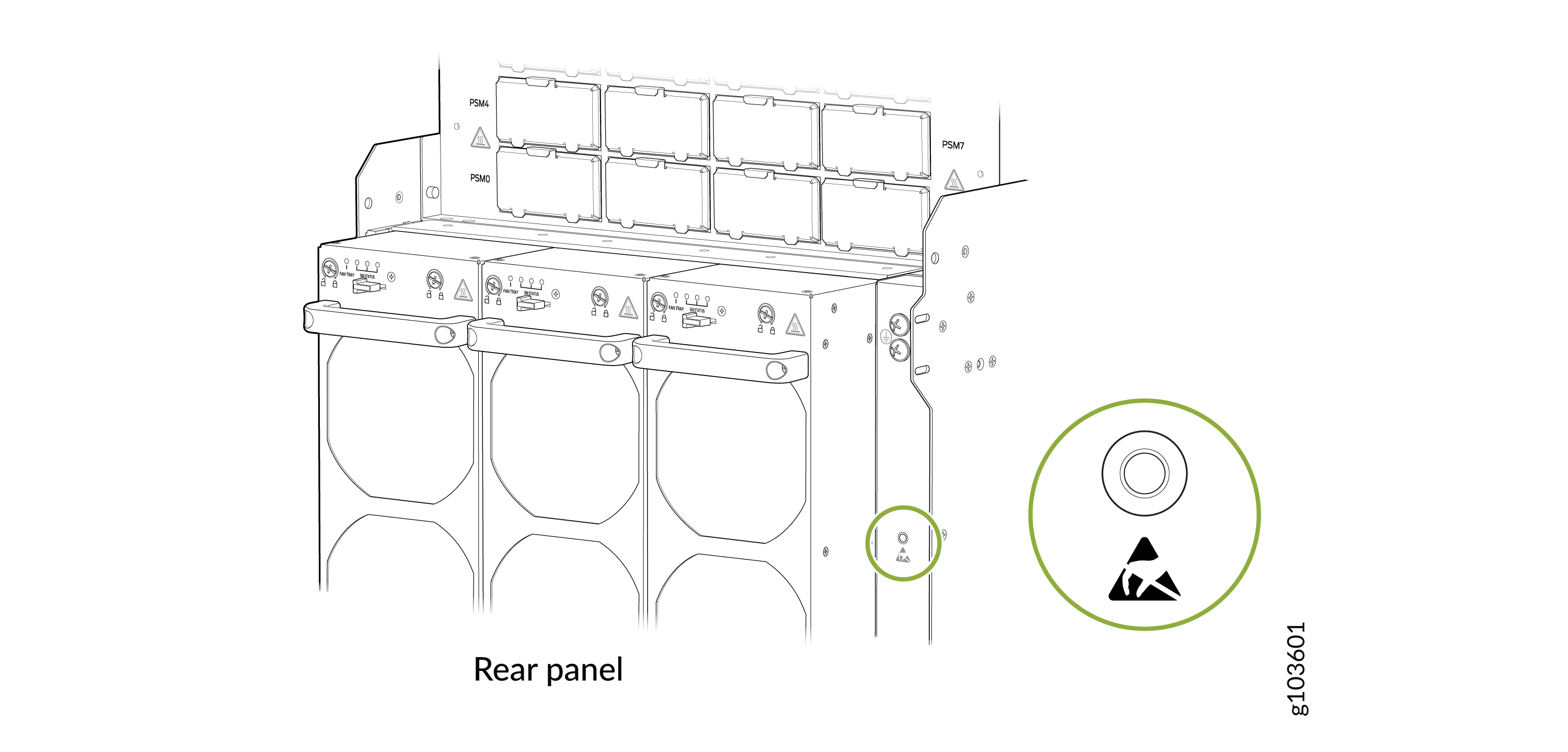
Ensure that all grounding surfaces are clean and brought to a bright finish before making the grounding connections.
Using a Phillips (+) screwdriver, number 3, remove the screws from the protective grounding terminal.
Place the 2-hole Panduit LCD4-14A-L protective grounding terminal lug (provided) and 4-AWG grounding cable over the protective grounding terminal screw holes.
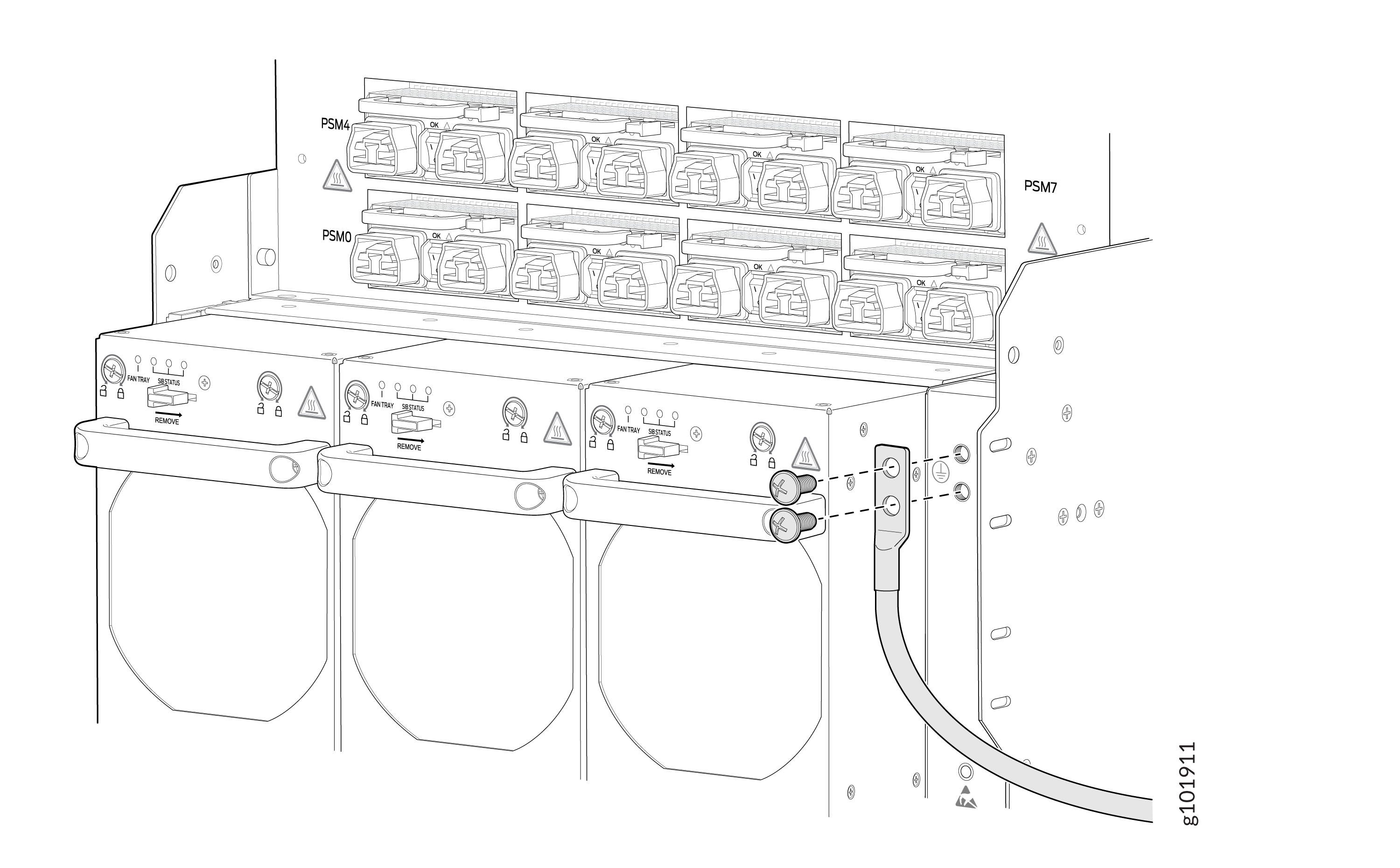
Secure the grounding cable terminal to the grounding point by using two M6 screws (provided) and a Phillips (+) screwdriver, number 3.
Tighten the screws by using the Phillips (+) screwdriver, number 3.
Dress the grounding cable and ensure that it does not touch or block access to other router components and that it does not drape where people can trip over it.
Install the AC/HVAC/HVDC Power Supply Module and Connect the PTX12008 Router to Power
For information about the supported PSMs, see PTX12008 Power System.
You must connect each PSM to a dedicated power source outlet.
Wrap and fasten one end of the ESD grounding strap around your bare wrist and connect the other end of the strap to the ESD point on the rear panel of the chassis.
Figure 6: ESD Point on the Rear Panel of the Chassis
If the PSM slot has a cover on it, pull the cover out of the slot. Store the cover for later use.
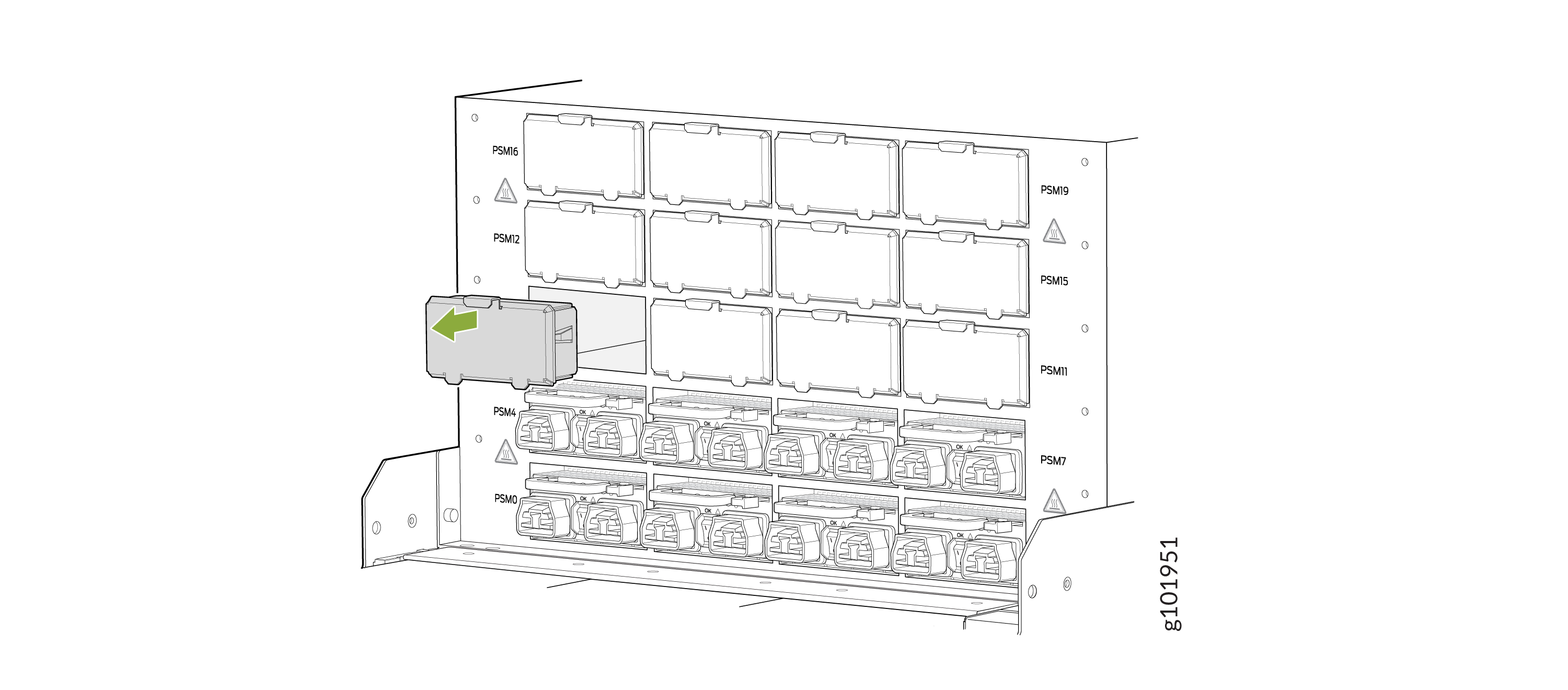
Taking care not to touch PSM components, pins, leads, or solder connections, remove the PSM from its bag.
If the PSM has a protective plastic wrap, peel and remove the plastic wrap from all the sides of the PSM.
Using both hands, place the PSM straight into the PSM slot on the rear panel of the chassis. Slide the PSM until it is fully seated and the ejector lever slides into place.
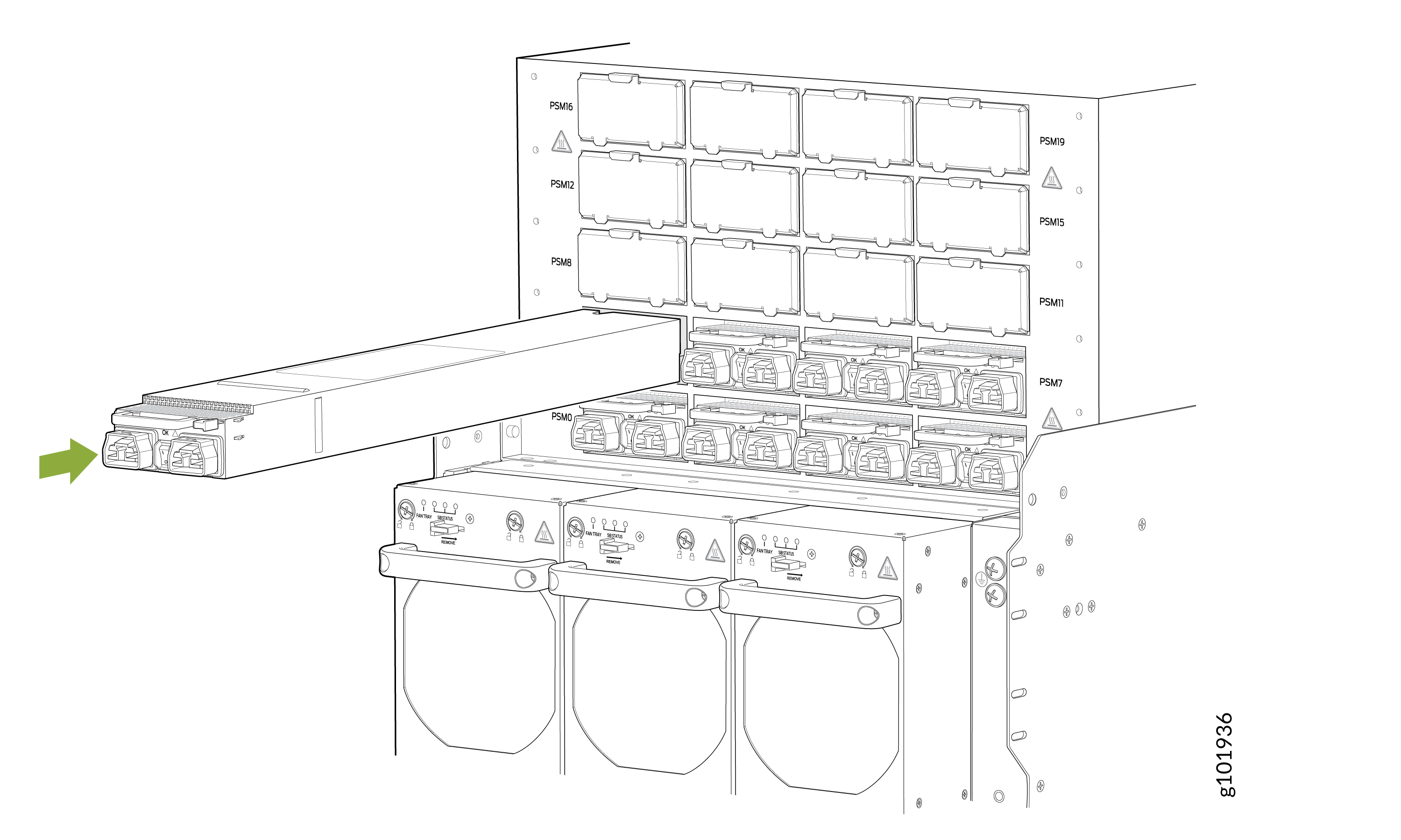
Set the power switch on the PSM to the off (O) position.
Insert the coupler end of the power cord appropriate for your geographical location into the power cord inlet on the PSM faceplate.
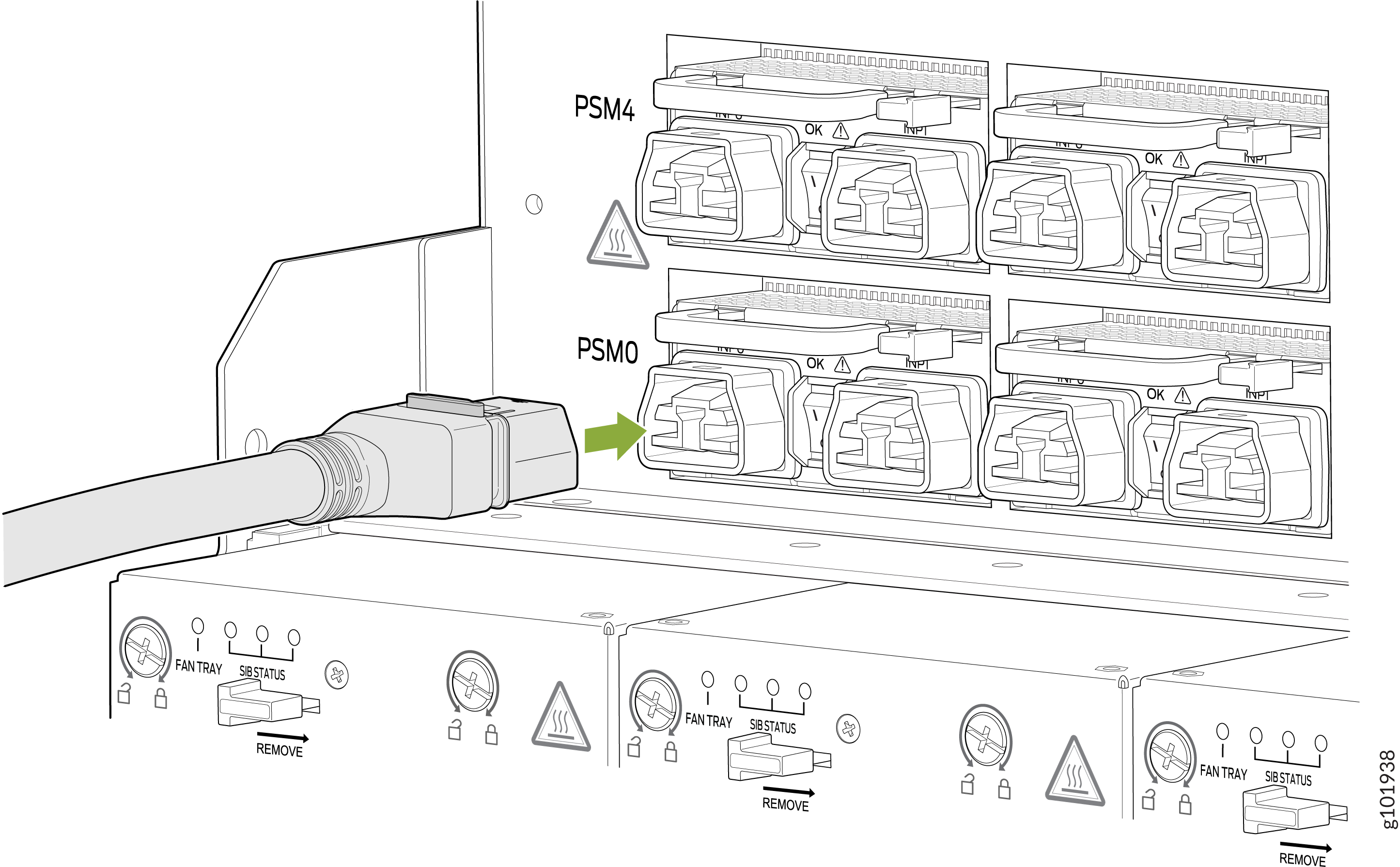
Dress the power cord and ensure that it does not touch or block access to other router components and that it does not drape where people could trip over it.
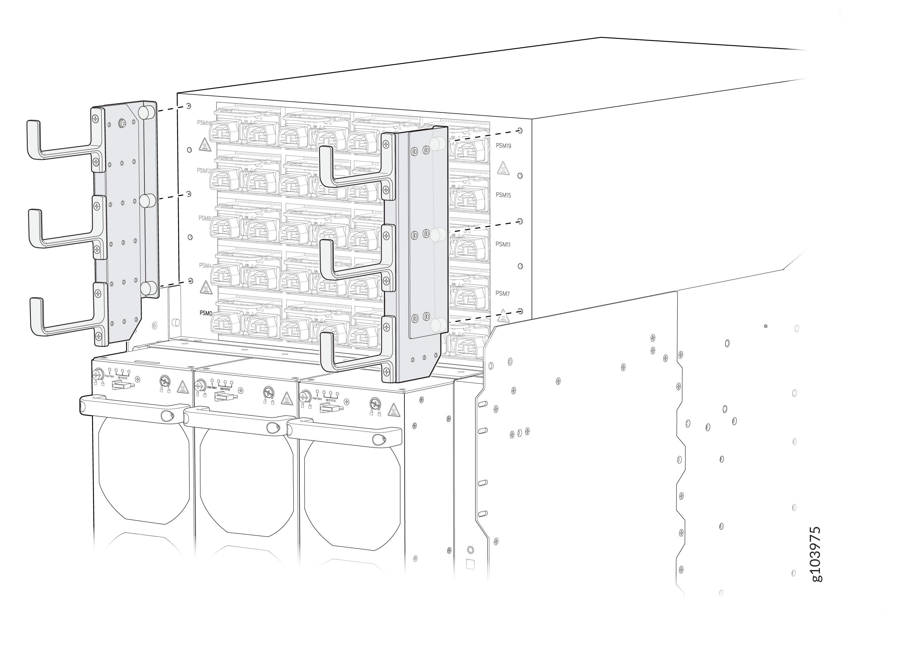
(Optional): Attach the power cable management system. Align the power cable management system brackets with the holes on either sides of the power shelf and tighten the screws by using your fingers.
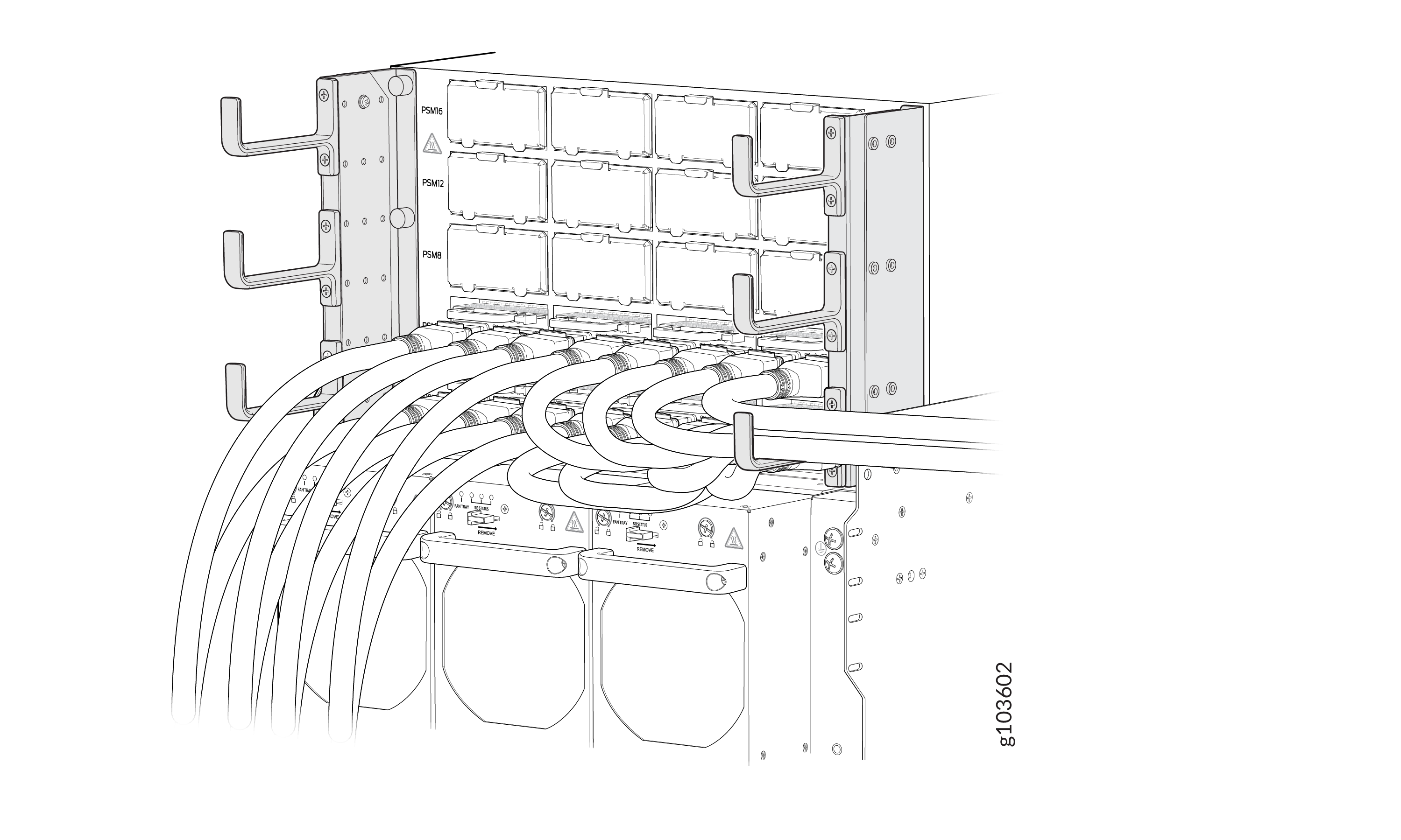
(Optional): Organize and route the power cables attached to the PSMs to prevent them from dislodging or developing stress points. This step also ensures proper airflow through the chassis. Secure the cables so that they are not supporting their own weight as they hang to the floor. Place excess cables out of the way in a neatly coiled loop. Placing fasteners on the loop helps to maintain the cable shape.
- Note: The router powers on as soon as power is provided to the PSM. There is no power switch on the router.
If the power source outlet has a power switch, set it to the off (O) position.
Insert the power cord plug into a power source outlet.
If the power source outlet has a power switch, set it to the on (|) position.
Set the power switch on the PSM to the on (|) position.
- Verify that the INP0, INP1, and OK LEDs on the PSM are lit green. If any LED is lit amber, remove power from the PSM and replace the PSM. Do not remove the PSM until you have a replacement PSM ready.
Install Field-Replaceable Units
To install Routing and Control Boards (RCBs), FPCs, transceivers, PSMs, Switch Interface Boards (SIBs), or fan trays in the chassis, see: