Replace Fan Trays in the PTX12008
Maintaining the cooling system in PTX12008 includes removing and installing the fan trays.
Fan trays in the PTX12008 are hot-removable and hot-insertable field-replaceable units (FRUs) installed on the rear panel of the chassis. You can remove and replace the fan trays without powering off the PTX12008 or disrupting the router functions.
Remove a Fan Tray from the PTX12008
Before you remove a fan tray:
-
Ensure that you understand how to prevent electrostatic discharge (ESD) damage. See Prevention of Electrostatic Discharge Damage.
-
Ensure that you have the following parts and tools available:
-
An ESD grounding strap—not provided
-
A replacement fan tray
-
A Phillips (+) screwdriver, number 2—not provided
-
A pair of heat resistant gloves—not provided
-
A hearing protection device—not provided
-
You must replace only one fan tray at a time. When one fan tray is removed, the remaining fan trays operate at 100% speed. When the replacement fan tray is installed, all the fan trays operate at the normal speed.
We recommend that you take offline the SIB behind the fan tray that you plan
to remove by using the request chassis
sib slot slot number offline
command.
|
Chassis Ambient Temperature |
Traffic (%) |
Optic Power per port |
Duration (mm:ss) |
|---|---|---|---|
|
20 °C |
Up to 25% |
Up to 30 W |
4:40 |
|
20 °C |
Up to 25% |
Up to 18 W |
5:50 |
|
30 °C |
Up to 25% |
Up to 30 W |
2:40 |
|
30 °C |
Up to 25% |
Up to 18 W |
2:40 |
|
30 °C |
0 |
Up to 30 W |
3:40 |
|
30 °C |
0 |
Up to 18 W |
5:00 |
|
40 °C |
0 |
Up to 18 W |
2:10 |
 Extreme burn danger—Do not handle a fan tray
running in the chassis without wearing heat-protective gloves.
Extreme burn danger—Do not handle a fan tray
running in the chassis without wearing heat-protective gloves.
Do not remove a fan tray running in the chassis without wearing a hearing protection device.
Do not remove a fan tray unless you have a replacement fan tray available.
To remove a fan tray:
-
Wrap and fasten one end of the ESD grounding strap around your bare wrist
and connect the other end of the strap to an ESD point on the rear panel of
the chassis.
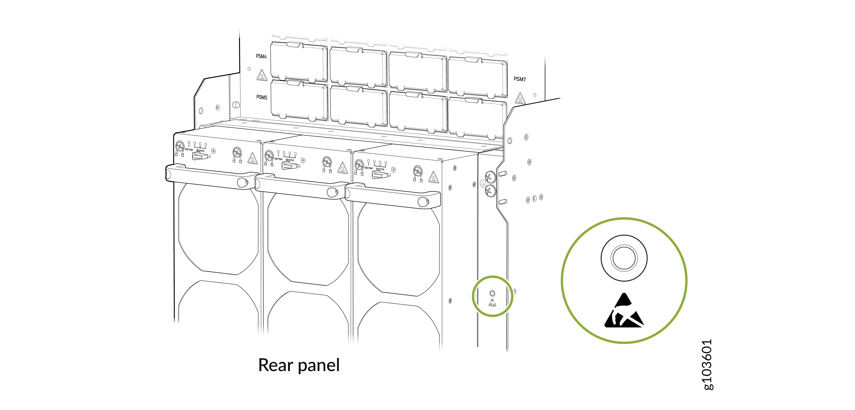
Figure 1: ESD Point on the Rear Panel of the Chassis
 CAUTION:The fan tray surfaces are hot.
 -
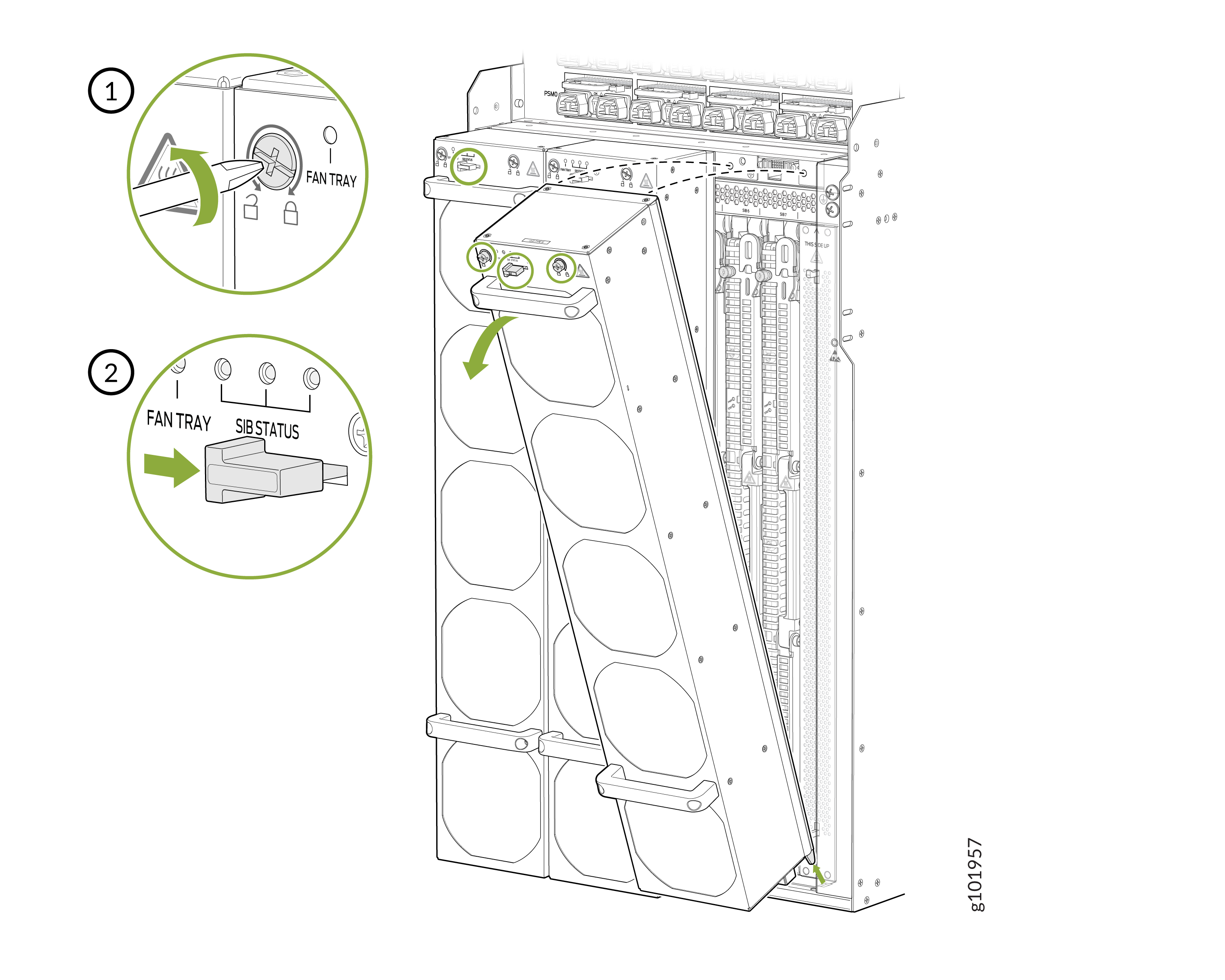
Loosen the two screws on the fan tray by using a Phillips (+) screwdriver,
number 2.
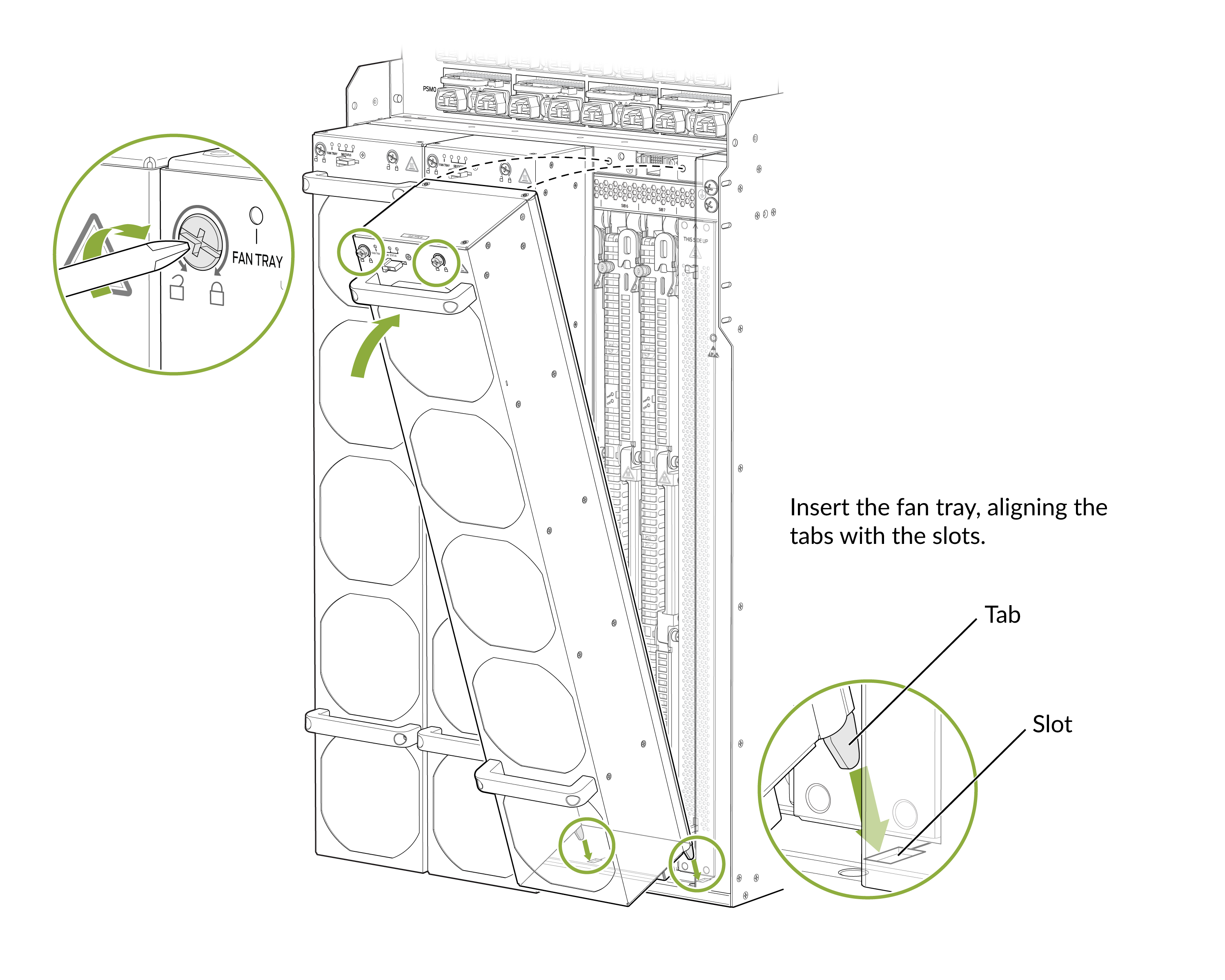
Figure 2: Remove a Fan Tray
Install a Fan Tray on the PTX12008
The fan trays are installed on the rear panel of the chassis.
Before you begin to install a fan tray:
-
Ensure that you understand how to prevent ESD damage. See Prevention of Electrostatic Discharge Damage.
-
Ensure that you have the following parts and tools available:
-
An ESD grounding strap—not provided
-
A Phillips (+) screwdriver, number 2—not provided
-
To install a fan tray:
-
Wrap and fasten one end of the ESD grounding strap around your bare wrist
and connect the other end of the strap to one of the ESD points on the rear
panel chassis.
Figure 3: ESD Point on the Rear Panel of the Chassis
-
Tilt the fan tray toward the chassis until it is vertical with the chassis
and is fully seated.
Figure 4: Install a Fan Tray