Replace the Switch Interface Board on the PTX12008
Maintaining the PTX12008 includes removing and installing the Switch Interface Boards.
A PTX12008 has up to nine Switch Interface Boards (SIBs) that are installed in the middle of the chassis, between the Flexible PIC Concentrators and the fan trays. SIB 0 through SIB 2 are located behind the left fan tray. SIB 3 through SIB 5 are located behind the middle fan tray. SIB 6 through SIB 8 are located behind the right fan tray.
The SIBs are hot-removable and hot-insertable field-replaceable units (FRUs). You can remove and replace the SIBs without powering off the PTX12008 or disrupting the router functions.
Remove a SIB from the PTX12008
You must remove the appropriate fan tray before you remove a SIB. See Remove a Fan Tray from the PTX12008.
Ensure that you have taken the necessary precautions to prevent electrostatic discharge (ESD) damage. See Prevention of Electrostatic Discharge Damage.
Ensure that you have the following parts and tools available:
-
An ESD grounding strap—not provided
-
An antistatic bag or antistatic mat—not provided
-
A replacement SIB or a cover for the SIB slot
-
A pair of heat resistant gloves—not provided
 Extreme burn danger—Do not handle a SIB running
in the chassis without wearing heat-protective gloves.
Extreme burn danger—Do not handle a SIB running
in the chassis without wearing heat-protective gloves.
To remove a SIB:
-
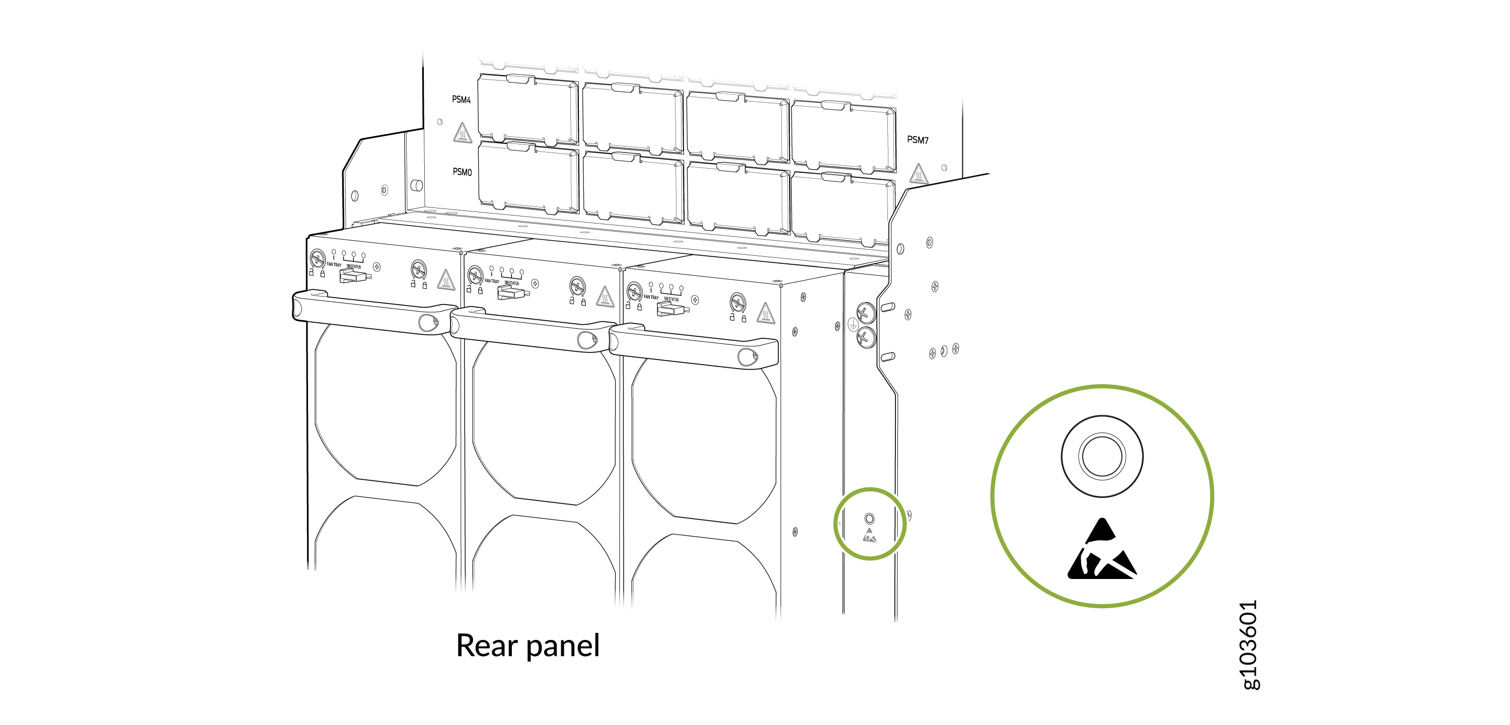
Wrap and fasten one end of the ESD grounding strap around your bare wrist
and connect the other end of the strap to the ESD point on the rear panel of
the chassis.
Figure 1: ESD Point on the Rear Panel of the Chassis
-
Remove the appropriate fan tray in front of the SIB slot (see Remove a Fan Tray from the PTX12008). The SIBs slots SIB 0 through SIB
2 are behind the fan tray on the left, SIB
3 through SIB 5 are behind the fan
tray in the middle, and SIB 6 through SIB
8 are behind the fan tray on the right.
CAUTION:The SIB surfaces are hot.
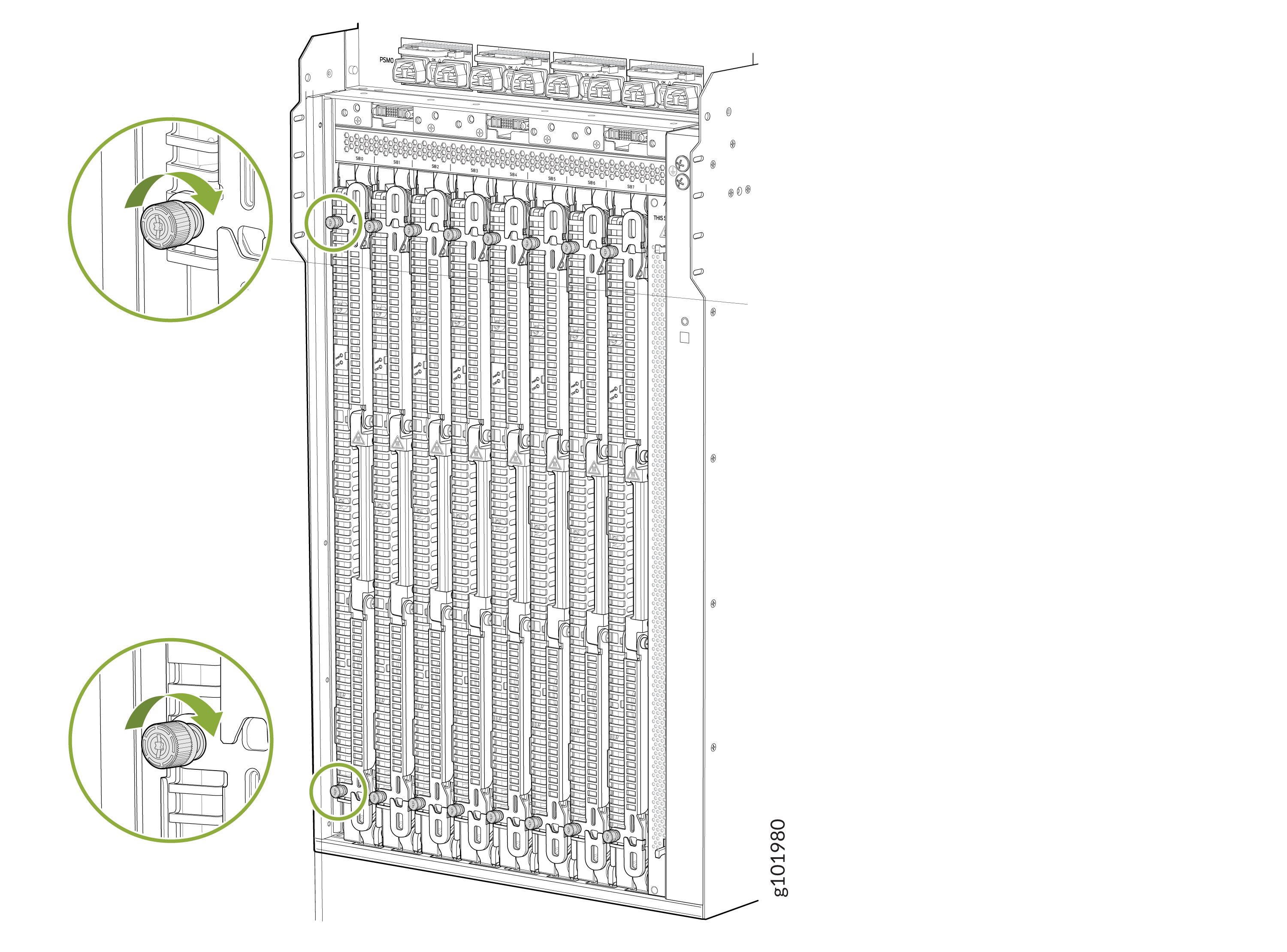
-
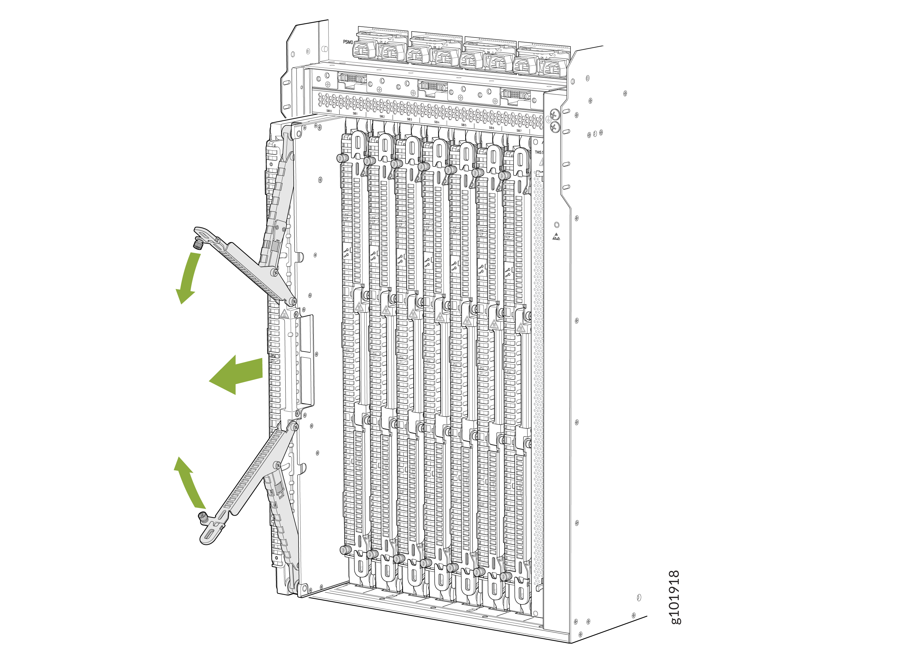
Using your fingers, loosen the captive screws at the top and bottom of the
SIB.
-
Grasp both ejector handles and pull them open simultaneously till the SIB
slides about a quarter of the way out of the slot.
Install a SIB on the PTX12008
You can install up to nine SIBs behind the fan trays. You must remove the appropriate fan tray before you install a SIB. See Remove a Fan Tray from the PTX12008.
Ensure that you have taken the necessary precautions to prevent ESD damage. See Prevention of Electrostatic Discharge Damage.
Ensure that you have the following parts and tools available:
-
An antistatic bag or antistatic mat—not provided
-
An ESD grounding strap—not provided
To install a SIB:
-
Wrap and fasten one end of the ESD grounding strap around your bare wrist
and connect the other end of the strap to the ESD point on the rear panel of
the chassis.
Figure 2: ESD Point on the Rear Panel of the Chassis
-
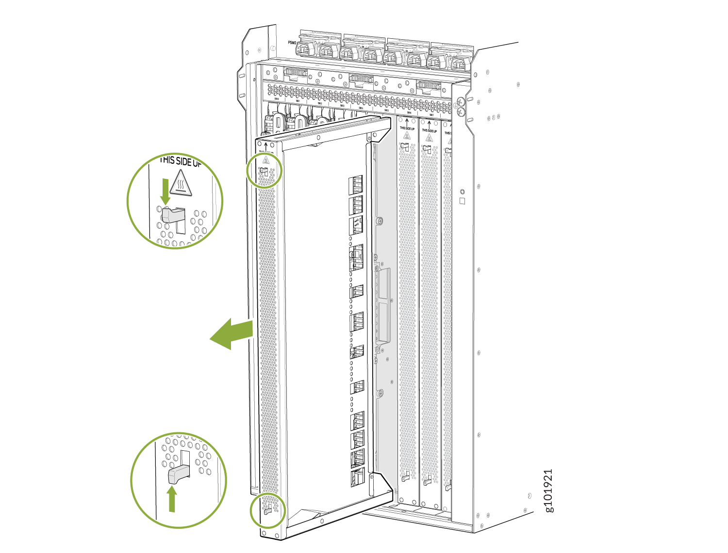
If the SIB slot is empty, remove the cover on the SIB slot. Push the top
latch down and the bottom latch up at the same time, and then pull the cover
straight out. If you are replacing a SIB, remove the SIB you would like to
replace (see Remove a SIB from the PTX12008).
Figure 3: Remove the SIB Slot Cover
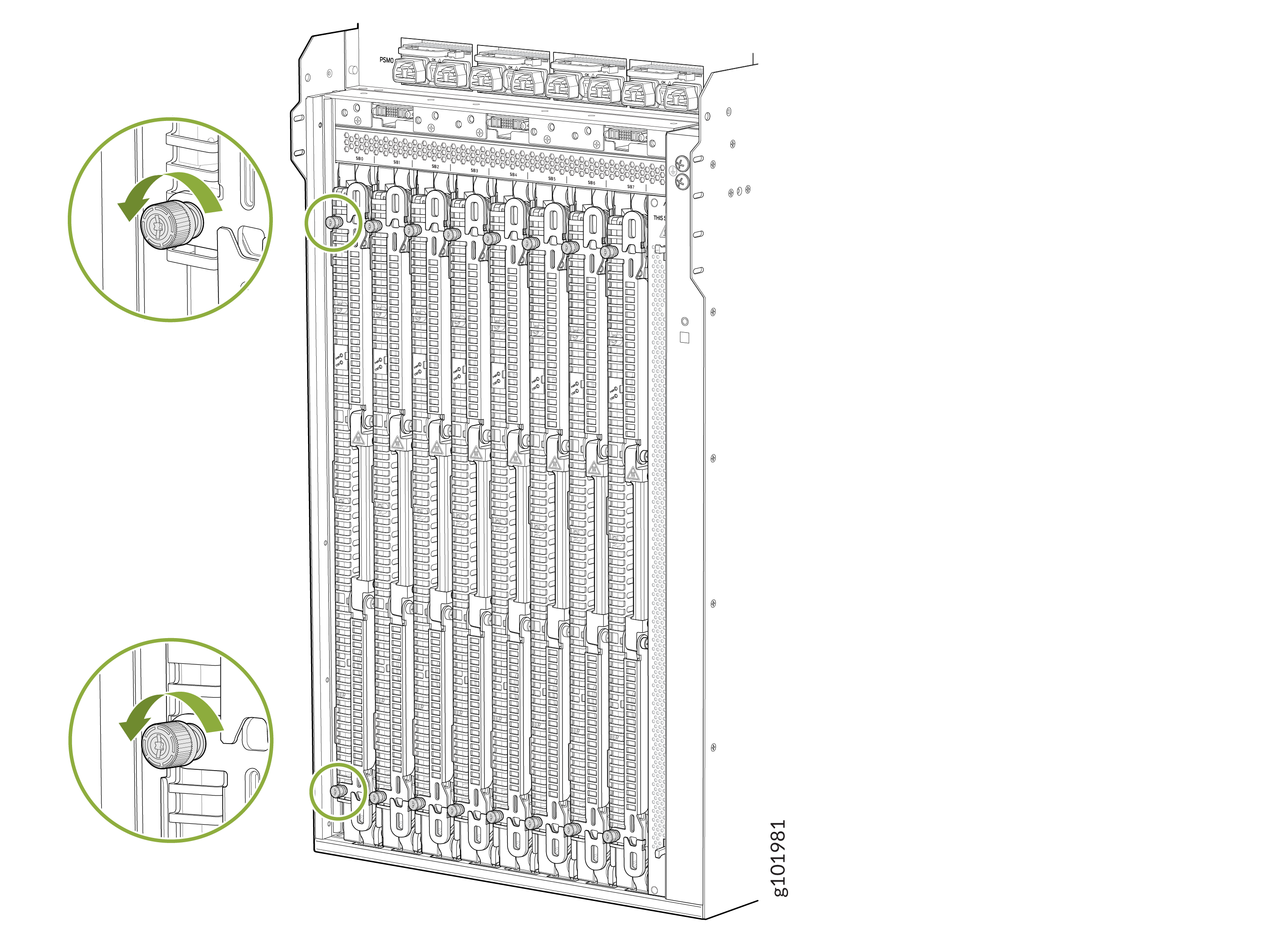
-
Grasp the ejector handles and fold them outward until they are fully
closed.
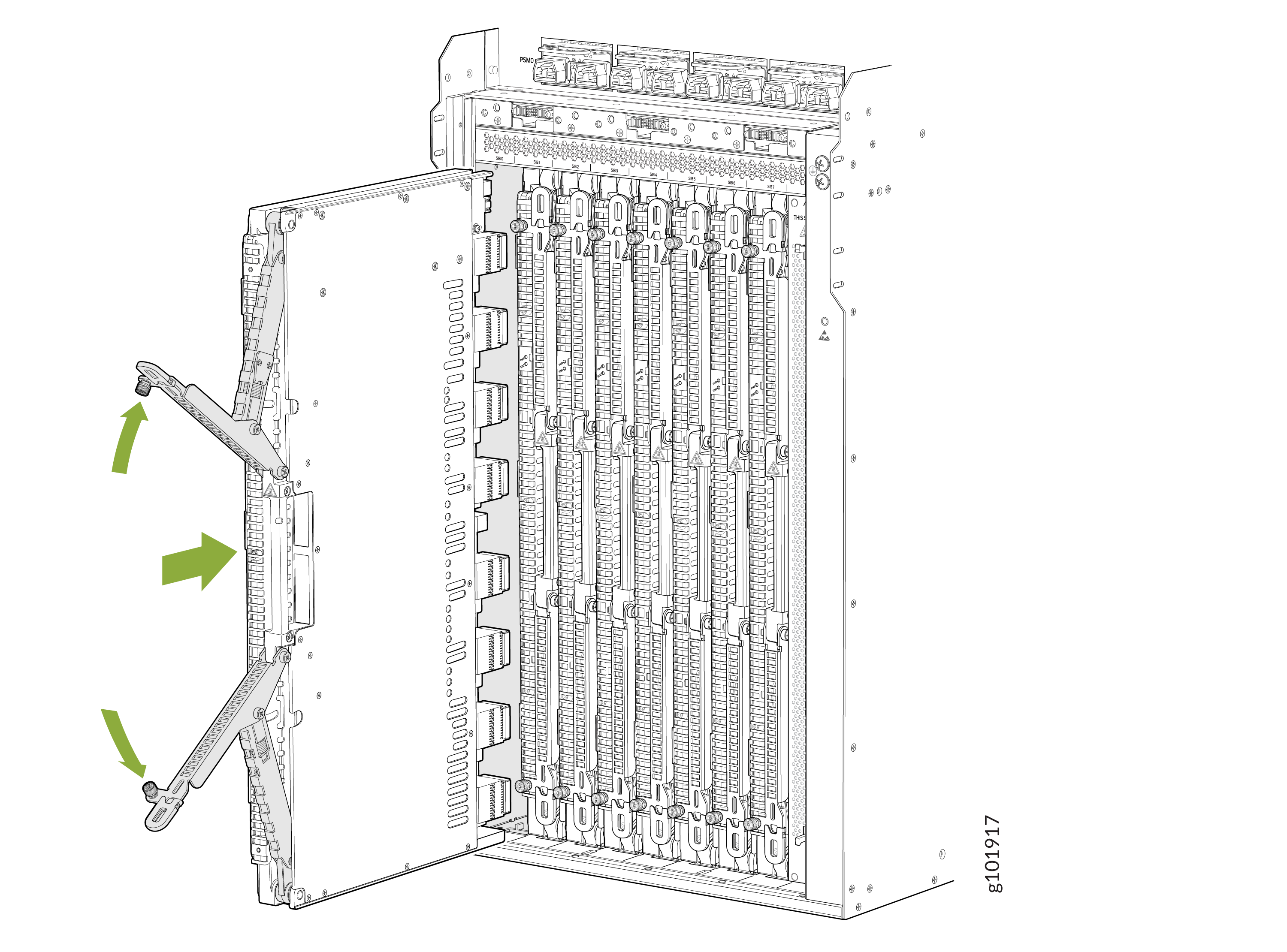
-
Tighten the captive screws on the ejector levers by using your
fingers.