Replace Flexible PIC Concentrators on the PTX12008
Maintaining the PTX12008 includes removing and installing the Flexible PIC Concentrators.
Flexible PIC Concentrators (FPCs) in the PTX12008 are hot-removable and hot-insertable field-replaceable units (FRUs). You can remove and replace the FPCs without powering off the PTX12008 or disrupting the router functions.
Remove an FPC from the PTX12008
Before you remove an FPC:
-
Ensure that you have taken the necessary precautions to prevent electrostatic discharge (ESD) damage. See Prevention of Electrostatic Discharge Damage.
-
If there are any optical cables or transceivers installed in the FPC, remove them. See Remove an OSFP or QSFP-DD Transceiver.
-
Ensure that you have the following parts and tools:
-
An ESD grounding strap—not provided
-
An antistatic bag or an antistatic mat—not provided
-
Two ejector tool handles —provided
-
A replacement FPC—not provided
-
A blank cover panel (in case you're not replacing the FPC)—provided
-
A second person to assist with handling the FPC, or a lift—not provided
-
To remove an FPC:
-
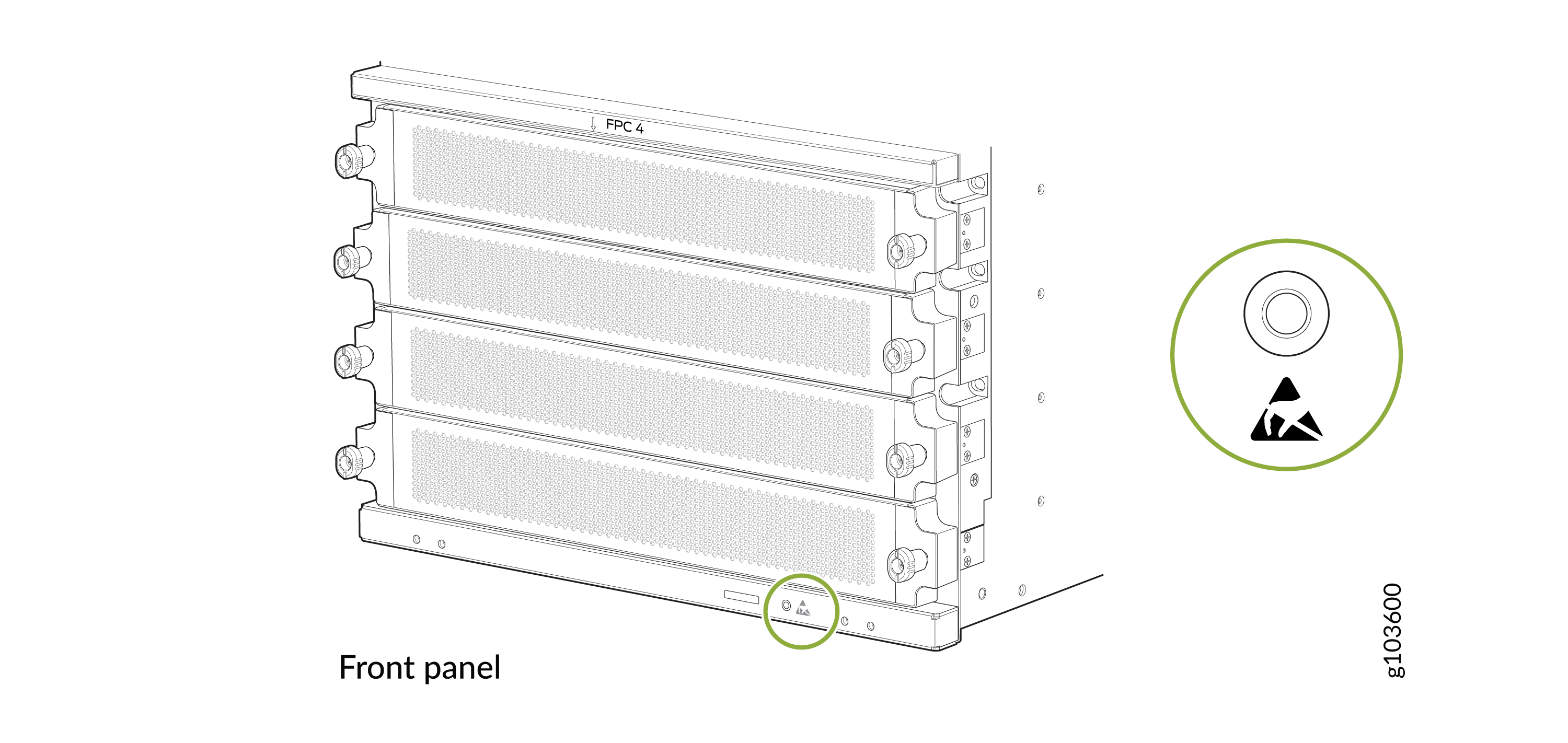
Wrap and fasten one end of the ESD grounding strap around your bare wrist
and connect the other end of the strap to the ESD point on the front panel
of the chassis.
Figure 1: ESD Point on the Front Panel of the Chassis
-
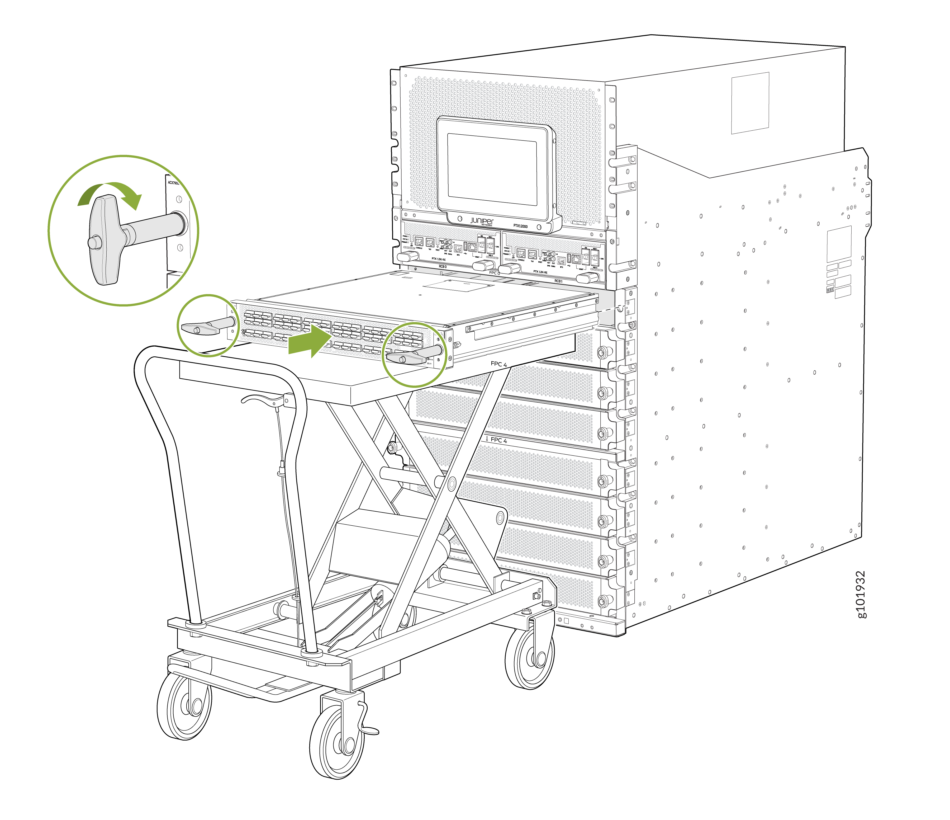
Hold the ejector tool handles and slide the FPC halfway out of the
chassis.
 CAUTION:
Do not stack FPCs on top of one another or on top of any other component. Place each FPC separately in the antistatic bag or on the antistatic mat placed on a flat, stable surface.
CAUTION:Do not lift the FPC by holding the edge connectors or the faceplate. The edge connectors or the faceplate cannot support the weight of the FPC. Lifting the FPC by the edge connectors or faceplate might bend them, which would prevent the FPCs from being properly seated in the chassis.
Install an FPC on the PTX12008
Before you install an FPC:
-
Ensure that you have taken the necessary precautions to prevent ESD damage. See Prevention of Electrostatic Discharge Damage.
-
Ensure that the router has sufficient power to power the FPC while maintaining its n+1 power redundancy. To determine whether the router has enough power available for the FPC, use the Power Calculator.
-
Ensure that you have the following parts and tools available:
-
An ESD grounding strap—not provided
-
A Phillips (+) screwdriver, number 2—not provided
-
Two ejector tool handles—provided
-
A second person to assist with handling the FPC, or a lift—not provided
-
To install an FPC:
-
Wrap and fasten one end of the ESD grounding strap around your bare wrist
and connect the other end of the strap to the ESD point on the front panel
of the chassis.
Figure 2: ESD Point on the Front Panel of the Chassis
-
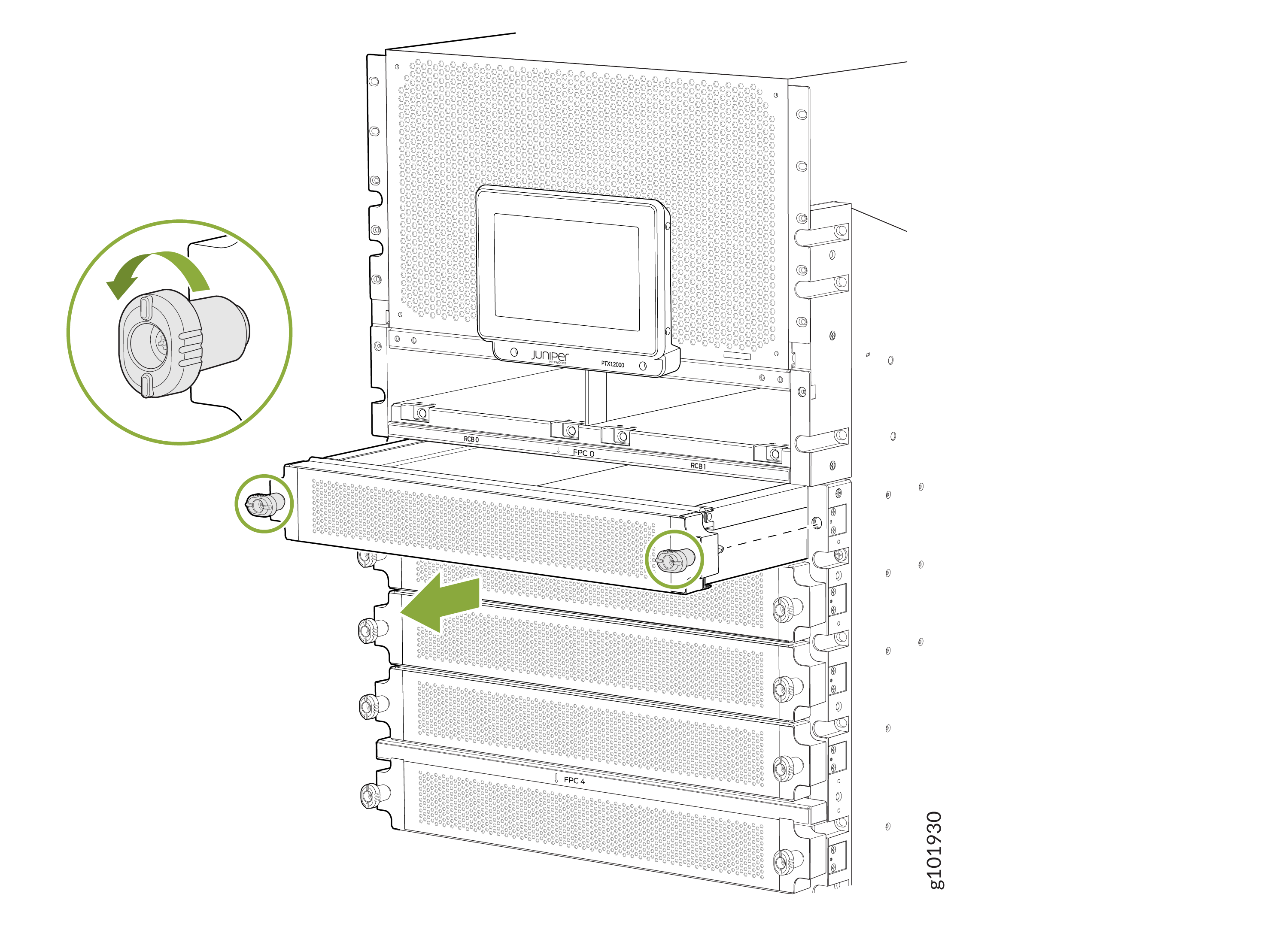
If the FPC slot is covered, turn the screws on the cover counterclockwise
and pull the slot cover gently out of the chassis. If there is an FPC
installed in the slot, remove it (see Remove an FPC from the PTX12008).
-
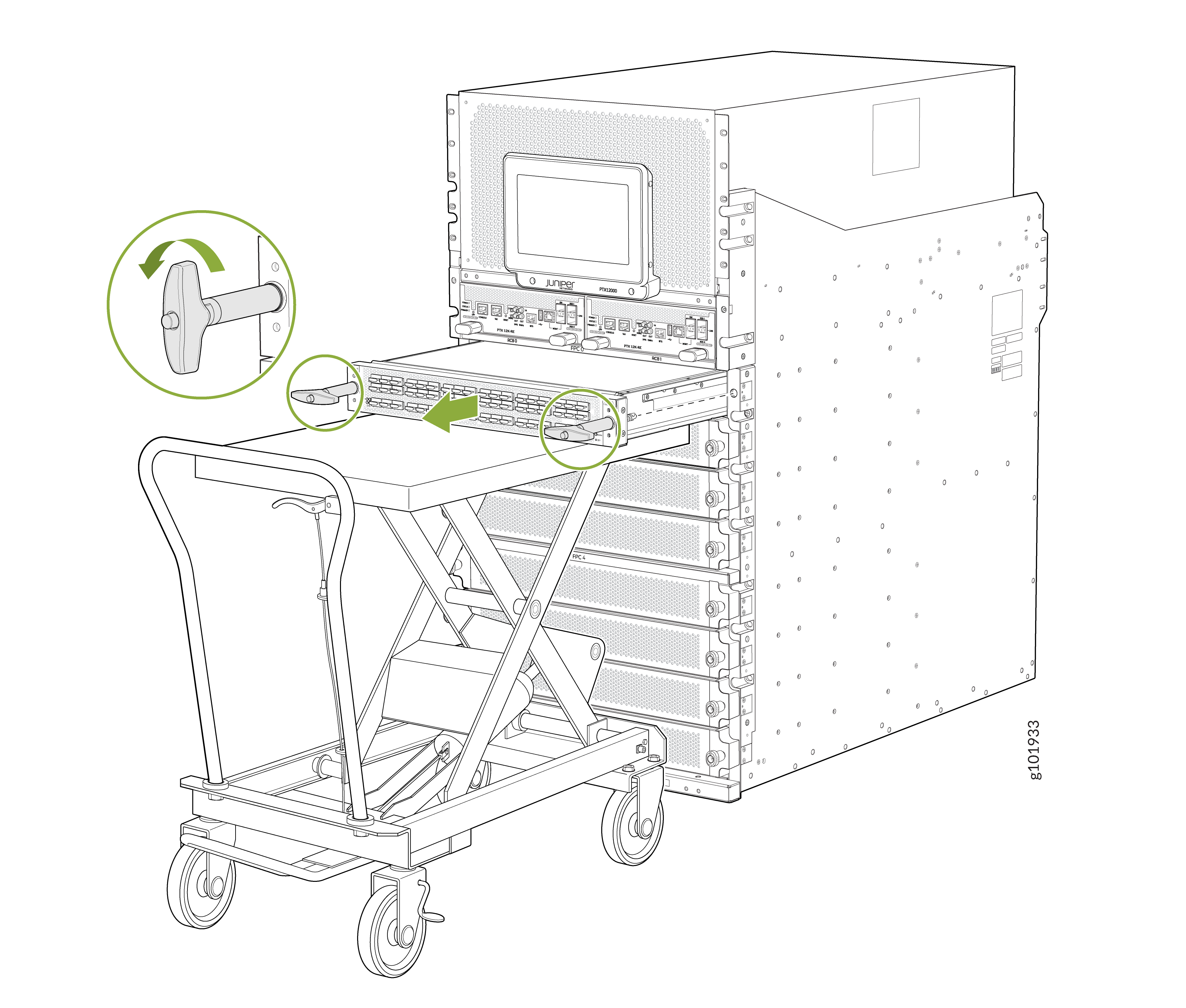
Slide the FPC all the way into the slot. Rotate the ejector tool handles
clockwise until the FPC is fully seated.