Replace the Routing and Control Board on the PTX12008
Maintaining the PTX12008 includes removing and installing the Routing and Control Board and removing solid-state drives.
The Routing and Control Board (RCB) in the PTX12008 is a hot-removable and hot-insertable field-replaceable unit (FRU) in a premium configuration. You can remove and replace the RCB without powering off the PTX12008 or disrupting the device functions. In a base configuration, you must install a second RCB before removing the first RCB to prevent the device from shutting down. The RCBs are installed in the RCB slots labeled RCB0 and RCB1 in the front panel of the chassis.
When you power on a router with a single RCB preinstalled in it, the RCB comes online as the primary RCB. The primary RCB powers on the Forwarding Engine Boards (FEBs) and the Flexible PIC Concentrators (FPCs). If you install the second RCB,the RCB comes online as the backup RCB.
When you power on a router for the first time with two RCBs installed, the RCB installed in slot RCB0 comes online as the primary RCB. This RCB then powers on the FEBs and the FPCs. The RCB installed in slot RCB1 comes online as the backup RCB by default. You can change this configuration by using the CLI.
The solid-state drives (SSDs) are located side-by-side under the opening in the top cover of an RCB.
Remove an RCB from the PTX12008
Before you remove an RCB:
-
Ensure that you understand how to prevent electrostatic discharge (ESD) damage. See Prevention of Electrostatic Discharge Damage.
-
Ensure that you have the following parts and tools available:
-
An ESD grounding strap—not provided
-
A replacement RCB
-
An antistatic bag or antistatic mat—not provided
-
To remove an RCB:
-
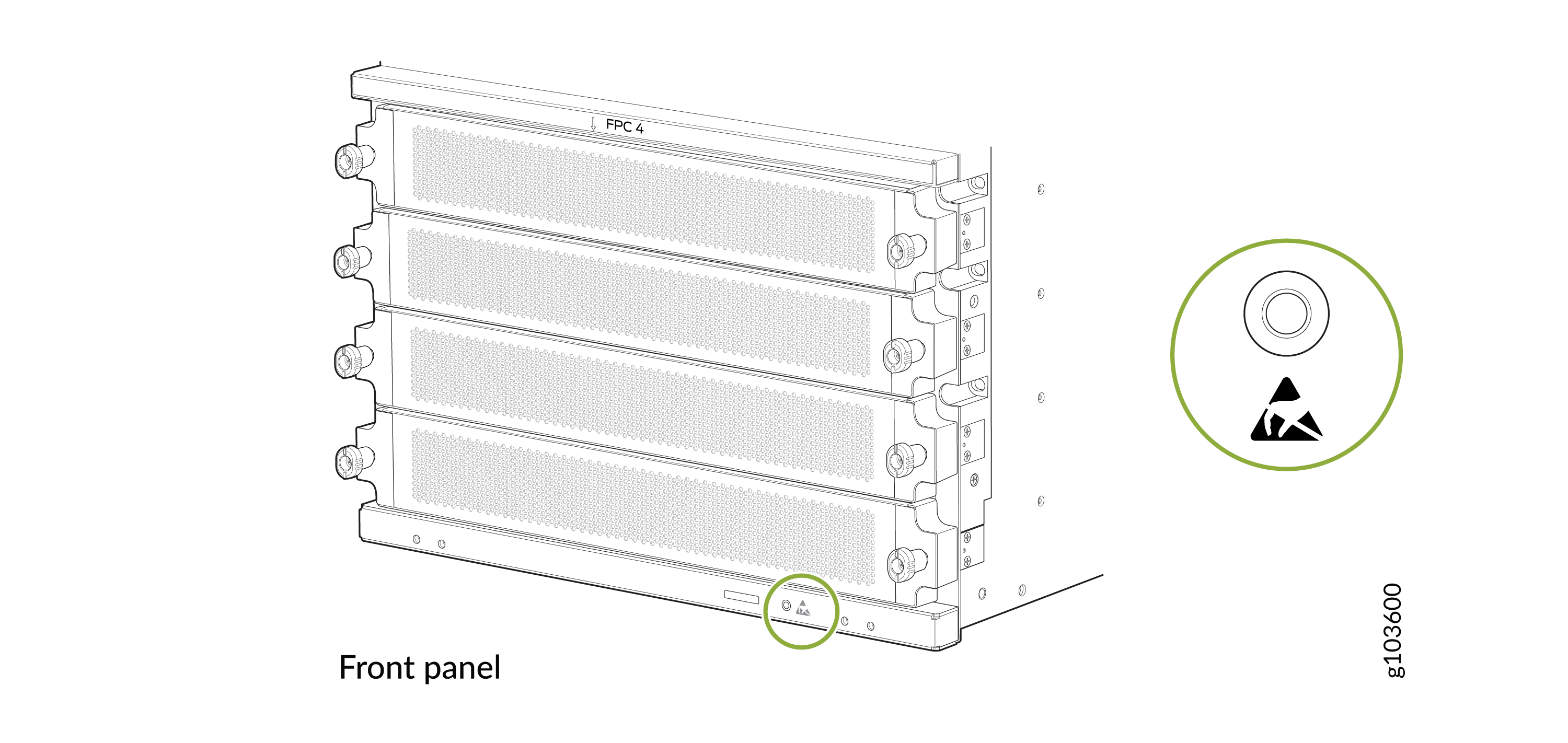
Wrap and fasten one end of the ESD grounding strap around your bare wrist
and connect the other end of the strap to an ESD point on the front panel of
the chassis.
Figure 1: ESD Point on the Front Panel of the Chassis
-
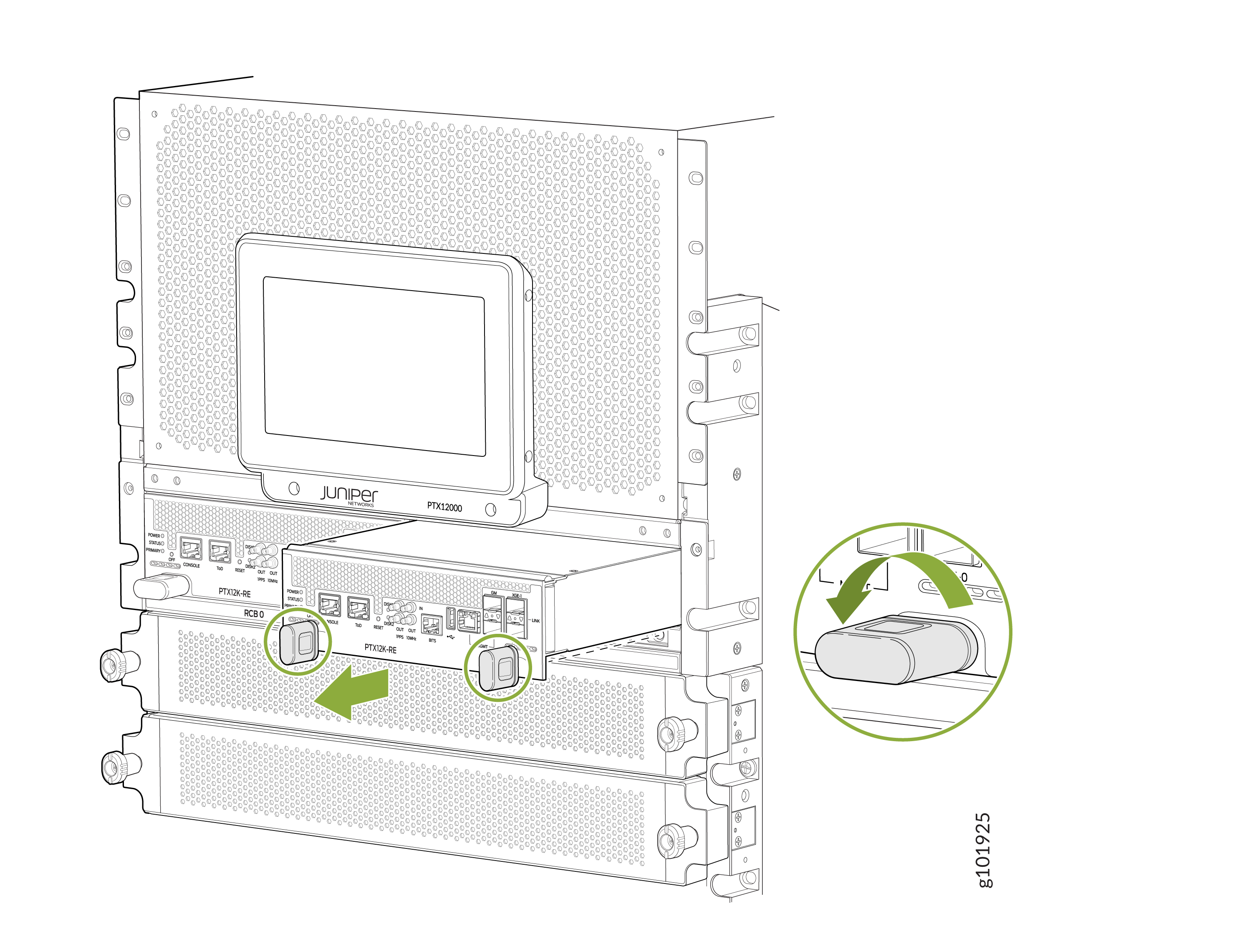
Grasp the handles and slide the RCB about halfway out of the chassis.
Figure 2: Remove an RCB
Install an RCB on the PTX12008
Before you install an RCB:
-
Ensure that you understand how to prevent ESD damage. See Prevention of Electrostatic Discharge Damage.
-
Ensure that you have an ESD grounding strap—not provided.
To install an RCB:
-
Wrap and fasten one end of the ESD grounding strap around your bare wrist
and connect the other end of the strap to an ESD point on the front panel of
the chassis.
Figure 3: ESD Point on the Front Panel of the Chassis
-
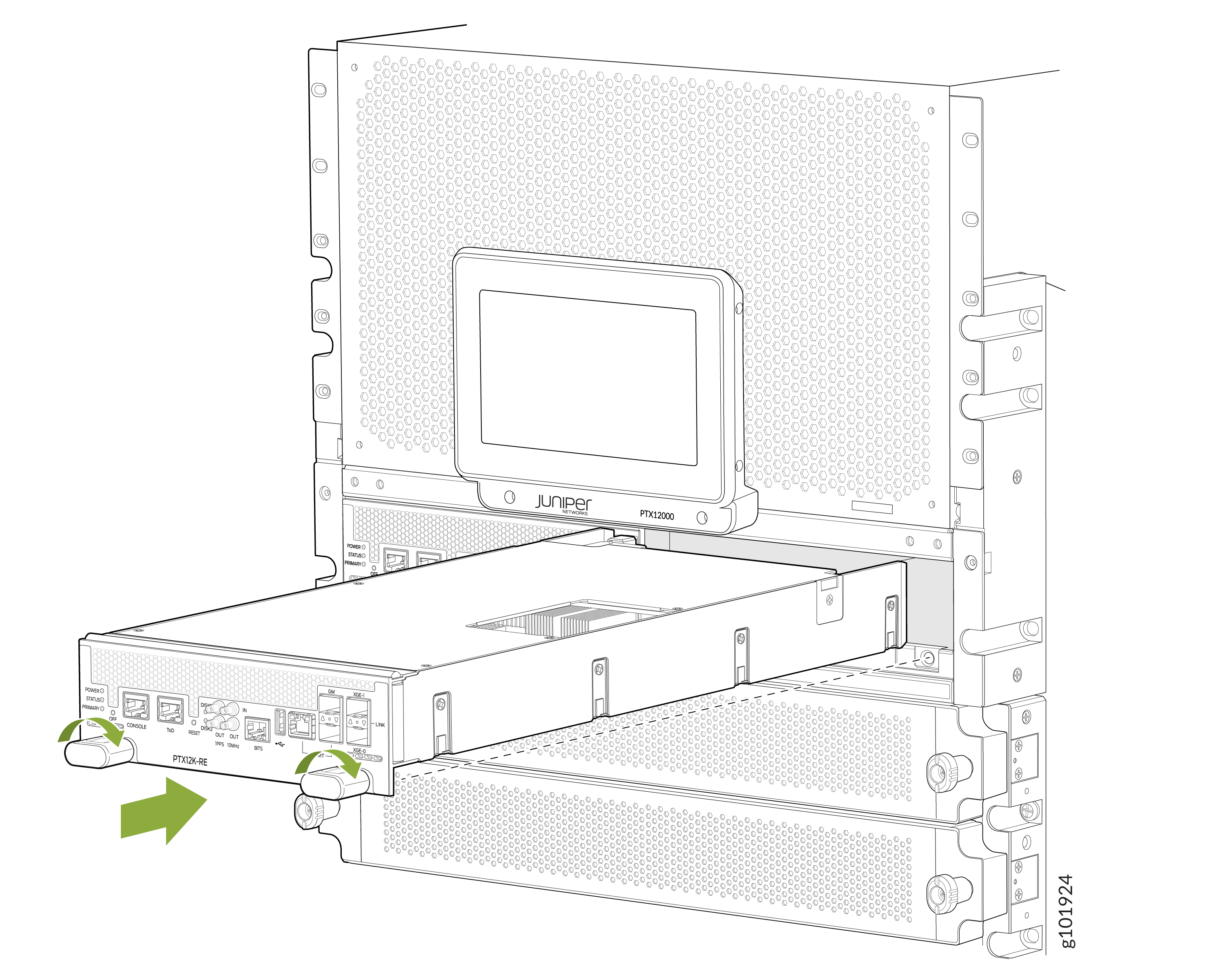
Grasp both handles on the RCB and rotate them simultaneously clockwise
until the RCB is fully seated and the handles are horizontal. The RCB begins
the power-on sequence when fully seated.
Figure 4: Install an RCB
Remove an SSD from the PTX12008 RCB
The SSDs are located side-by-side under the opening in the top cover of an RCB. If you need to return an RCB, you can remove the SSD to protect any sensitive information.
Before you remove an SSD:
-
Ensure that you understand how to prevent ESD damage. See Prevention of Electrostatic Discharge Damage.
-
Ensure that you have the following parts and tools available:
-
A Phillips (+) screwdriver, number 1—not provided
-
An antistatic bag or antistatic mat—not provided
-
To remove an SSD:
- Place an electrostatic bag or antistatic mat on a flat, stable surface.
- If the RCB from which you want to remove the SSD is installed in the chassis, remove it (see Remove an RCB from the PTX12008).
- Remove the screw from one end of the SSD by using a Phillips (+) screwdriver, number 1.
- Disengage the SSD from the connector at the other end.
- Remove the bush on the screw slot below the SSD.
- Place the SSD on the antistatic mat or in the antistatic bag.