PTX10004 System Overview
PTX10004 Hardware Overview
The Juniper Networks PTX10004 Packet Transport Router addresses the business challenges of carriers and content providers to deliver more traffic at lower costs. For more information, read the following topics.
- System Overview
- Benefits
- Chassis Description
- Switch Fabric
- Routing and Control Board
- Line Cards
- Cooling System
- Power Supplies
- Software
System Overview
The PTX10004 is the most compact, high-density, and power-efficient modular chassis in the PTX10000 line of modular packet-routing transport routers. At only 7 U in height, the PTX10004 is designed for today’s space-constrained facilities. Like the larger PTX10008 router, the PTX10004 supports Juniper’s 800GbE architecture with inline Media Access Control Security (MACsec) on all ports for point-to-point security on Ethernet links. Each PTX10K-LC1301-36DD line card installed in PTX10004 with JNP10004-SF3 has a throughput of up to 12.8 Tbps. Each PTX10K-LC1201-36CD line card has a throughput of up to 14.4 Tbps, giving the chassis an effective switching capacity of 57.6 Tbps. That throughput means a fully equipped PTX10004 can support 576 10GbE, 576 25GbE, 144 40GbE, 576 100GbE, 144 400GbE, or 144 800GbE interfaces in a single chassis. Each PTX10K-LC1202-36MR line card has a throughput of up to 4.8 Tbps. The PTX10004 supports the same feature set and runs the same Junos OS Evolved operating system as the PTX10008.
You can manage and monitor PTX10004 router by using the CLI. In addition to the CLI, you can manage and monitor the PTX10004 router by using Juniper Routing Director (formerly Juniper Paragon Automation) or Juniper Paragon Automation.
Benefits
The PTX10004 Packet Transport Router is the small-footprint complement to the larger PTX10008 modular chassis with these benefits:
-
Ease of deployment—The PTX10004 features a compact 7-U modular chassis for sites with limited space or power.
-
Modular, flexible design—The PTX10004 uses the custom silicon line cards and power supplies used in the larger PTX10008 modular chassis.
-
Proven fabric and chassis design—The PTX10004 has the same updated fabric and chassis design features found on the PTX10008 router.
Chassis Description
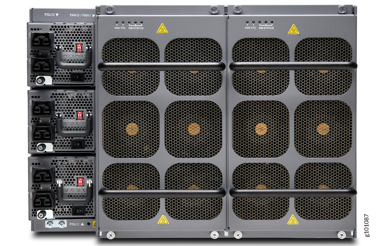
The PTX10004 router is 7-U tall. You can fix up to six PTX10004 routers in a standard 42-U rack with adequate cooling and power. All key PTX10004 router components are field-replaceable units (FRUs). Figure 1 illustrates the key components visible from the front of the chassis, Figure 2 illustrates the components that are visible from the rear of the chassis, and Figure 3 illustrates the components that are internal to the chassis.
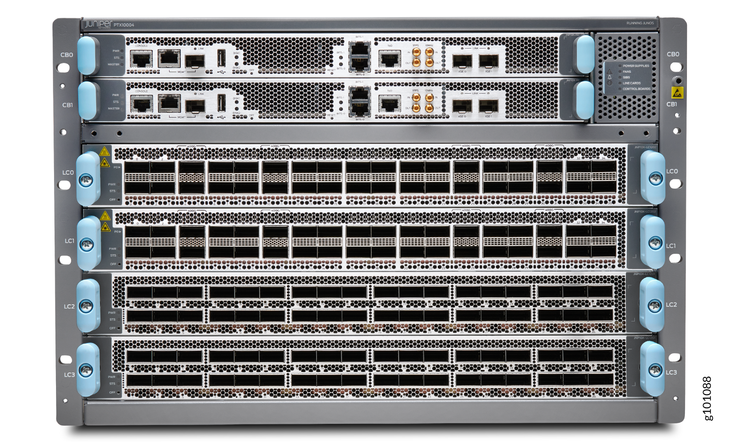

1 — Fan tray controllers | 2 — Switch fabric |
See PTX10004 Chassis Physical Specifications and PTX10004 Field-Replaceable Units.
Switch Fabric
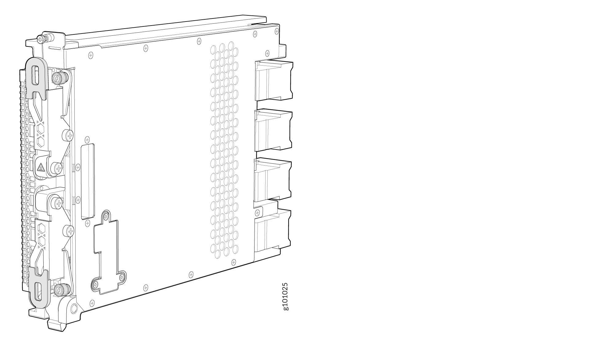
Switch Interface Boards (SIBs) create the switch fabric for the PTX10004. Each SIB has a set of connectors to mate the line cards and the Routing and Control Board (RCB) to the switch fabric. See Figure 4 for an example of the JNP10004-SF3.
For the JNP10004 switch fabric, three SIBs provide the minimum switching functionality to a PTX10004 router; six SIBs provide full throughput. SIBs are installed between the line cards and the fan trays inside the chassis. Each PTX10004 SIB has four connectors that match to a line-card slot, eliminating the need for a backplane. See PTX10004 Switch Interface Board Description.
You can order the PTX10004 with different SIB configurations that allow you to grow your system as needed. See Table 1. For full 400 Gbps or 800 Gbps deployments, we recommend the PTX10004-PREM3 configuration. See PTX10004 Components and Configurations for a full description of these configuration options.
|
Configuration |
Number of SIBs |
Forwarding Capacity |
|---|---|---|
|
PTX10004-BASE3 |
3 |
28.8 Tbps |
|
PTX10004–PREM2 |
4 |
38.4 Tbps |
|
PTX10004-PREM3 |
6 |
57.6 Tbps |
Routing and Control Board
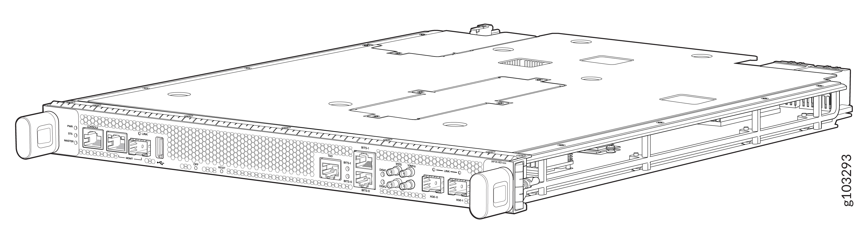
The Routing and Control Board (RCB) contains a Routing Engine and is responsible for system management and system control in the PTX10004. See PTX10004 Routing and Control Board Components and Descriptions. RCBs are field-replaceable units (FRUs) that are installed in the front of the chassis in the slots labeled CB0 and CB1.
The supported models of RCB for JNP10004-SF3 fabric systems are:
-
JNP10K-RE3-E, 128 gigabytes of memory
-
JNP10K-RE3-E-LT, 128 gigabytes of memory
-
JNP10K-RE1-E, 64 gigabytes of memory
-
JNP10K-RE1-E128, 128 gigabytes of memory
-
JNP10K-RE2-E128, 128 gigabytes of memory
The two variants of JNP10K-RE3-E (JNP10K-RE3-E, JNP10K-RE3-E-LT) have the same form factor.
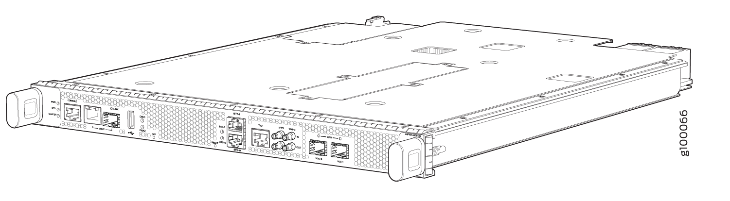
The base configuration has a single RCB. The fully redundant configurations have two RCBs. The RCB also contains Precision Time Protocol (PTP) ports and four Media Access Control Security (MACsec) capable ports. See PTX10004 Components and Configurations.
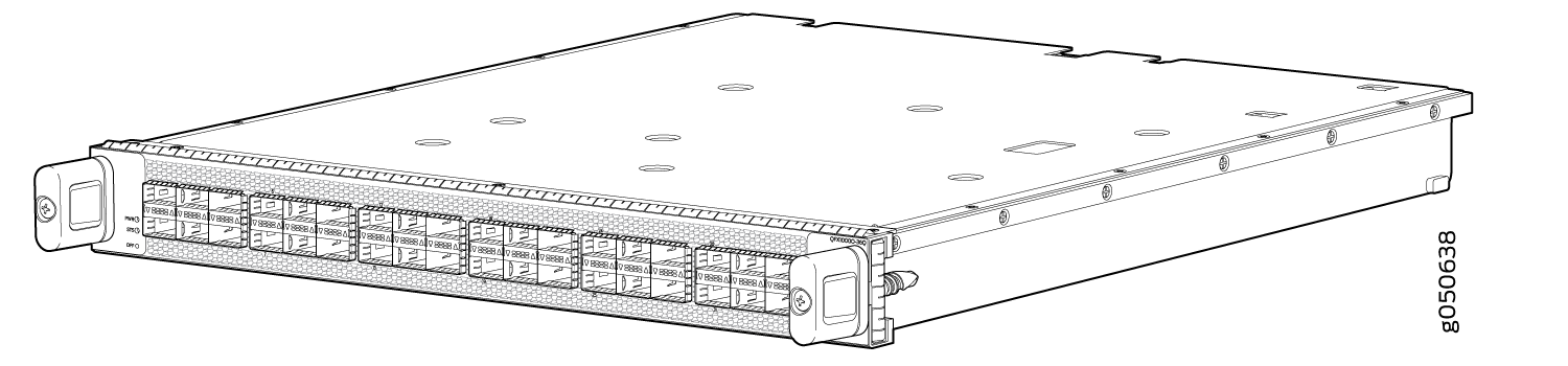
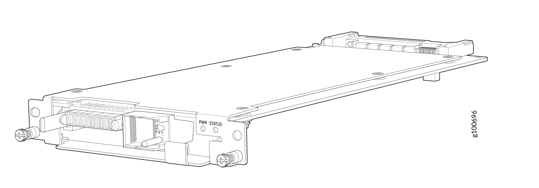
Line Cards
The PTX10004 has four horizontal line-card slots. The line cards combine a Packet Forwarding Engine and Ethernet interfaces enclosed in a single assembly. The PTX10004 line-card architecture is based on a number of identical, independent Packet Forwarding Engine slices. Line cards are FRUs that can be installed in the line-card slots labeled 0 through 3 (top to bottom) on the front of the chassis. All line cards are hot-removable and hot-insertable. After the hot insertion, you need to bring the card online (see Take a PTX10004 Line Card Online or Offline).
The PTX10004 supports:
-
PTX10K-LC1201-36CD—a 36-port multiple-speed line card that can be configured as 400GbE, 200GbE, 100GbE, 50GbE, 25GbE, or 10GbE Ethernet ports.
-
PTX10K-LC1202-36MR—A 36-port line card (thirty-two 100GbE ports and four 400GbE ports). The 400-Gigabit Ethernet ports can be configured as either 400-Gigabit uplinks or channelized to 4 independent 100-Gigabit downstream ports.
-
PTX10K-LC1301-36DD—A 36-port line card that offers a line rate throughput of 28.8 Tbps (with 18 W optical transceivers). The 36 high-density 800-Gigabit Ethernet (800GbE) QSFP-DD ports support speeds of up to 800 Gbps.
The maximum throughput that the line card offers in PTX10004 routers with JNP10004-SF3 installed is 12.8 Tbps.
See Figure 7 for an example of a PTX10004 line card.
Cooling System
The cooling system in a PTX10004 consists of two fan trays (see Figure 8, Figure 9), and two fan tray controllers (see Figure 10).
The JNP10004-FAN3 is the latest fan tray which uses powerful fans offering higher airflow within the system than its predecessor fan trays.
The JNP10004-FAN3 fan tray contains six fan modules, each with two counter-rotating fans. JNP10004-FAN3 fan tray operates as a single hot-removable and hot-insertable field-replaceable unit (FRU). The fan trays are installed vertically on the rear of the chassis and provide front-to-back chassis cooling. See PTX10004 Cooling System and Airflow.
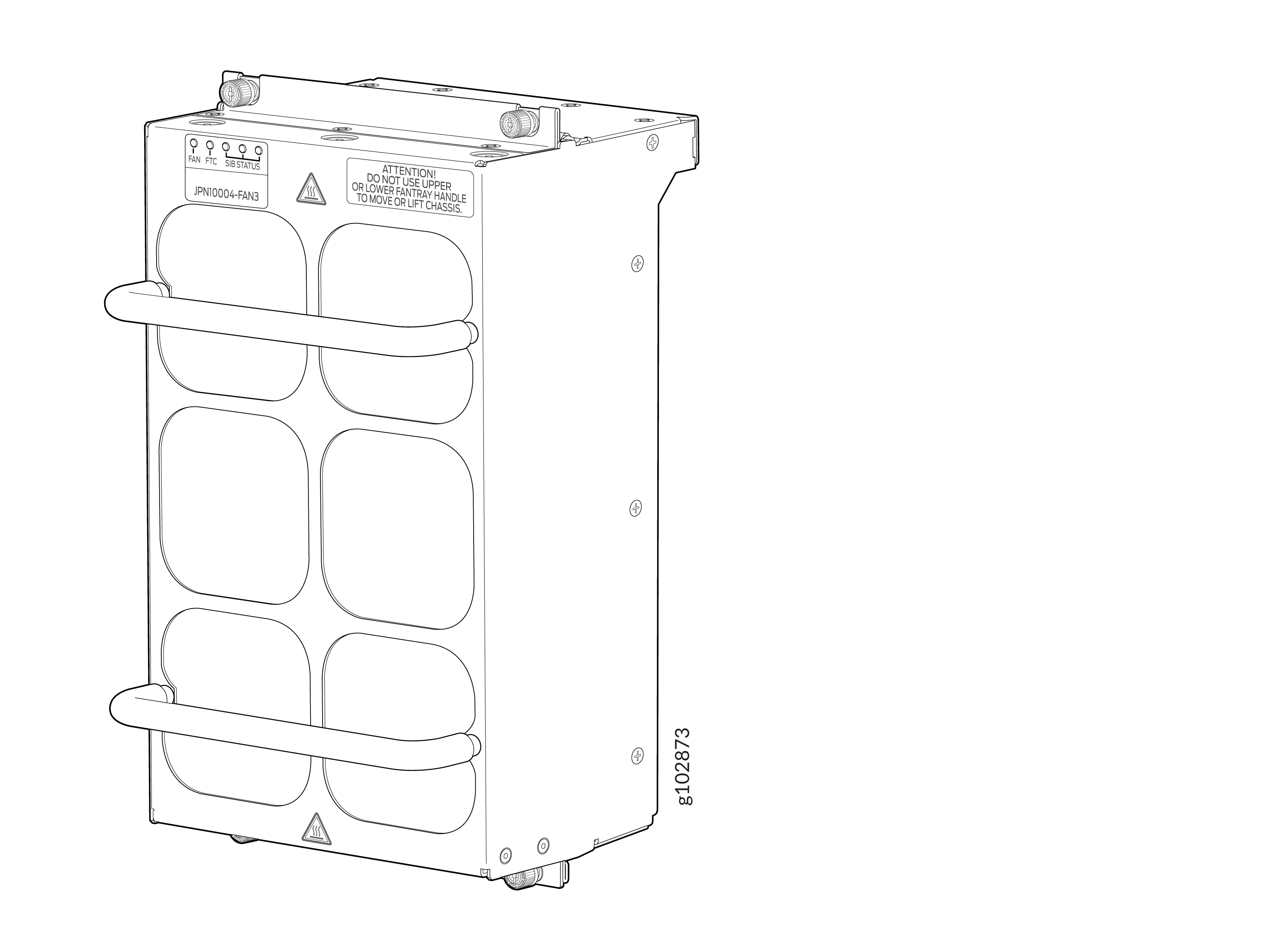
Each JNP10004-FAN3 fan tray has a corresponding fan tray controller, JNP10004-FTC3. See Figure 10.
The JNP10004-FAN2 fan tray containssix fans and operates as a single hot-removable and hot-insertable field-replaceable unit (FRU). The fan trays install vertically on the rear of the chassis and provide front-to-back chassis cooling. See PTX10004 Cooling System and Airflow.
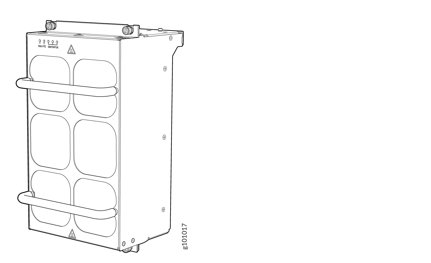
There is a corresponding fan tray controller, JNP10004-FTC2, for each JNP10004-FAN2 fan tray. See Figure 10.
Power Supplies
The PTX10004 router support AC, DC, high-voltage alternating current (HVAC), and high-voltage direct current (HVDC), by offering the following power supplies:
-
JNP10K-PWR-AC3
-
JNP10K-PWR-AC2
-
JNP10K-PWR-DC3
-
JNP10K-PWR-DC2
-
JNP10K-PWR-AC3H
Power supplies for the PTX10004 are load-sharing hot-removable and hot-insertable FRUs. The router operates with three power supplies. Each power supply has an internal fan for cooling. You can install the power supplies in any slot. See Figure 11, Figure 12, and Figure 14.
Do not mix power supply models in the same chassis in a running environment.
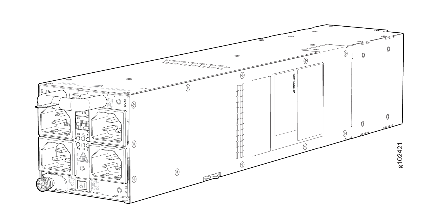
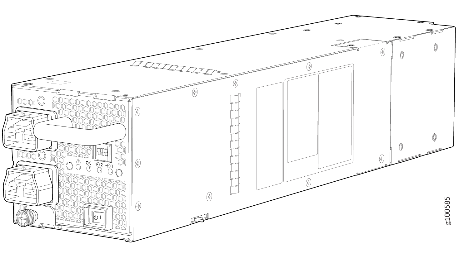
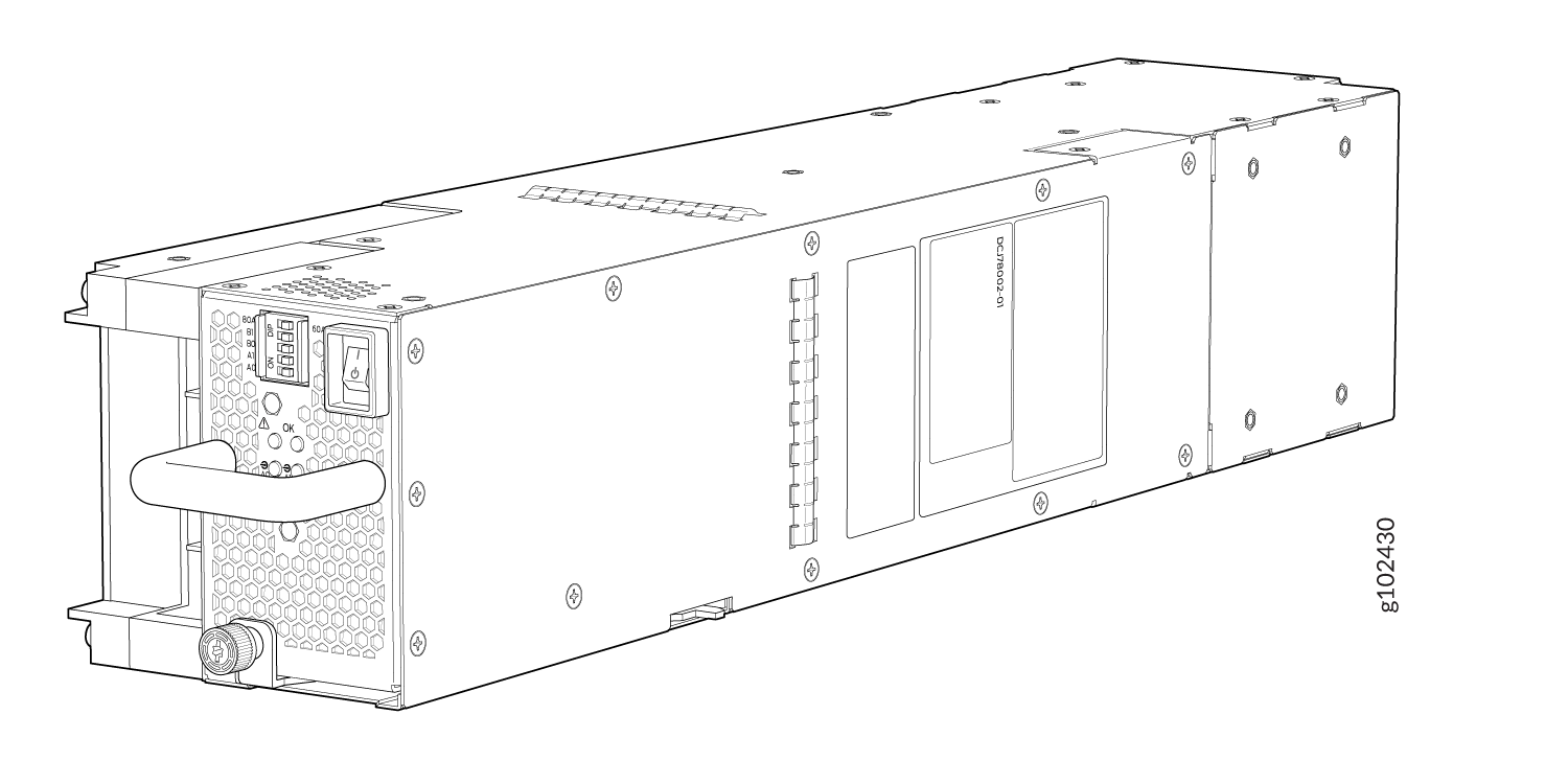
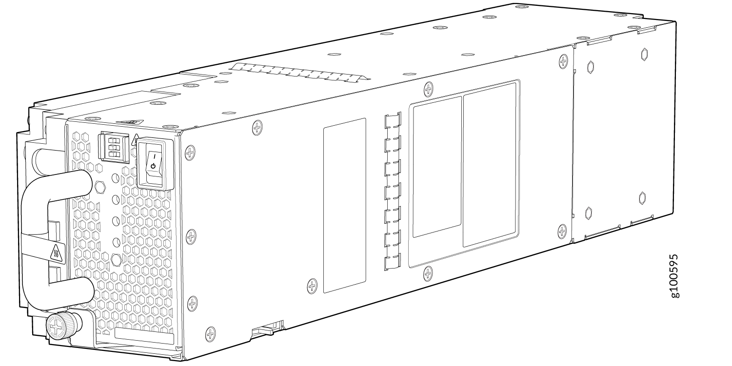
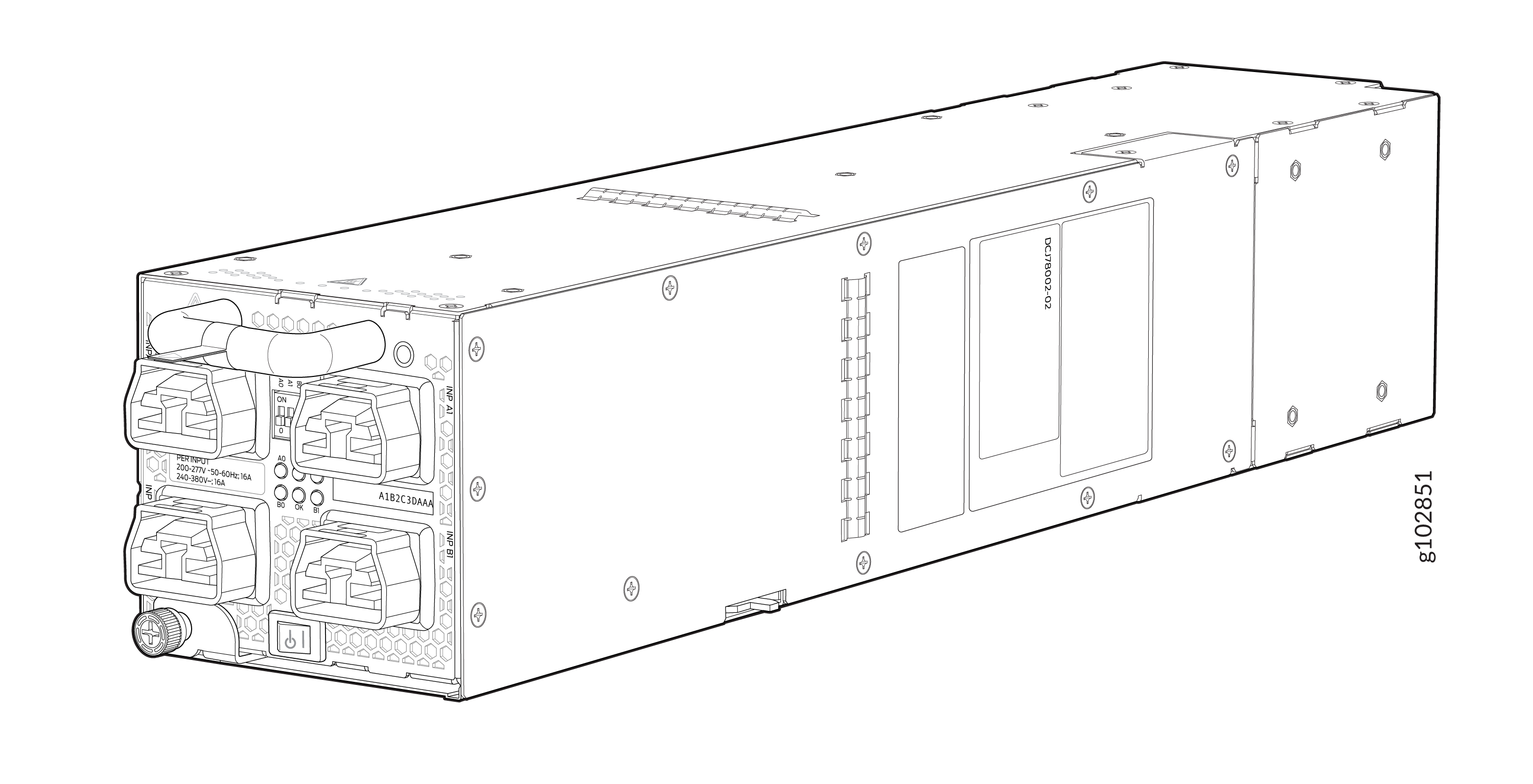
Table 2 provides an overview of the differences between the power supplies.
|
Power Supply Model |
Input Type |
Wattage |
|---|---|---|
|
JNP10K-PWR-AC3 |
AC |
|
|
JNP10K-PWR-AC2 |
AC, HVAC, or HVDC |
5000 W, single feed; 5500 W, dual feed |
|
JNP10K-PWR-DC3 |
DC only |
|
|
JNP10K-PWR-DC2 |
DC only |
2750 W, single feed; 5500 W, dual feed |
| JNP10K-PWR-AC3H | HVAC or HVDC |
|
While using JNPR10K-PWR-AC3, JNPR10K-PWR-DC3, or JNPR10K-PWR-AC3H power supplies, the PTX10004 supports four PTX10K-LC1301-36DD or PTX10K-LC1201-36CD line cards in non-redundant mode. If you populate all four slots with these line cards, a power alarm is raised, which is expected behavior.
While using JNP10K-PWR-AC2 or JNP10K-PWR-DC2 power supplies, the PTX10004 supports four PTX10K-LC1201-36CD line cards in non-redundant mode. If you populate all four slots with this line card, a power alarm is raised, which is expected behavior.
Software
The Juniper Networks PTX10004 packet transport router runs on the Junos OS Evolved operating system, which provides Layer 3 routing services. Junos OS Evolved is the next-generation Junos OS. It has the same CLI, the same features, and, in some cases, even the same processes as in the previous versions of Junos OS. However, its infrastructure is entirely modernized.
See Also
PTX10004 Components and Configurations
PTX10004 Configurations
Table 3 lists the hardware configurations for a PTX10004 modular chassis and the components included in each configuration.
|
Router Configuration |
Configuration Components |
|---|---|
|
Base AC configuration PTX10004-BASE3 |
|
|
Base DC configuration PTX10004-BASE3 |
|
|
Redundant AC configuration PTX10004-PREM2 |
|
|
Redundant DC configuration PTX10004-PREM2 |
|
|
Fully redundant AC configuration PTX10004-PREM3 |
|
|
Fully redundant DC configuration PTX10004-PREM3 |
|
Line cards and the cable management system are not part of the base or redundant configuration. You must order them separately.
If you want to purchase additional power supplies (AC, DC, HVAC, or HVDC), SIBs, or RCBs for your router configuration, you must order them separately.
See Also
PTX10004 Component Redundancy
The PTX10004 router is designed so that no single point of failure can cause the entire system to fail. The following major hardware components in the redundant configuration provide redundancy:
-
Routing and Control Board (RCB)—The RCB consolidates the Routing Engine function with the control plane function in a single unit. The PTX10004 router can have one or two RCBs. When two RCBs are installed, one functions as the primary and the other functions as the backup. If the primary RCB (or either of its components) fails, the backup can take over as the primary. See PTX10004 Routing and Control Board Description.
-
Switch Interface Boards (SIBs)—The PTX10004 has six SIB slots. The switch fabric requires a minimum of three SIBs (BASE3 configuration) to provide the minimum switching functionality to a PTX10004 router. You must install up to six SIBs for PTX10K-LC1201-36CD, PTX10K-LC1202-36MR, or PTX10K-LC1301-36DD line cards support. With JNP10004-SF3, there is no redundancy for switch fabric. Each of the six switch fabric boards provides one-sixth of the full switching fabric bandwidth. However, a fully-loaded PTX10004 chassis with PTX10K-LC1201-36CD line cards is not a redundant configuration. See the PTX10004 Switch Interface Board Description.
-
Power supplies—The system requires three power supplies for minimum operation (two RCBs, two fan trays, three SIBs, and no line cards). The three power supplies provide n+1 redundancy and can tolerate a failure of a single power supply without system interruption. If one power supply fails in a fully redundant system, the other power supplies can provide full power to the PTX10004 router indefinitely.
The PTX10004 router also supports power source redundancy. Four sets of lugs are provided for the JNP10K-PWR-DC2 cables, and two AC power cords are provided for each JNP10K-PWR-AC2 power supply.
-
Cooling system—The PTX10004 has two fan trays, which are controlled by the fan tray controller. Each fan tray has a corresponding fan tray controller. If one of the fans in a JNP10004-FAN2 or JNP10004-FAN3 fan tray fails, under most conditions the fan tray rebalances the remaining fans to continue. The fan tray continues to operate indefinitely and provide sufficient cooling even when a single rotor fails in a fan, provided the room temperature is within the operating range. See PTX10004 Cooling System and Airflow.
PTX10004 Hardware and CLI Terminology Mapping
This topic describes the hardware terms used in PTX10004 router documentation and the corresponding terms used in the Junos OS CLI. See Table 4.
|
Hardware Item (CLI) |
Description (CLI) |
Value (CLI) |
Item In Documentation |
Additional Information |
|---|---|---|---|---|
|
Chassis |
PTX10004 |
– |
Router chassis |
|
|
Fan tray |
JNP10004-FAN2 JNP10004-FAN3 |
n is a value in the range of 0–11. The value corresponds to the individual fan number in the fan tray. |
Fan tray |
|
|
FPC (n) |
Abbreviation for the Flexible PIC Concentrator (FPC) On PTX10004, an FPC is equivalent to a line card. |
n is a value in the range of 0–3 for the PTX10004. The value corresponds to the line-card slot number in which the line card is installed. |
Line card (The router doesn’t have actual FPCs—the line cards are the FPC equivalents on the router.) |
|
|
PIC (n) |
– |
Value of n is always 0. |
– |
|
|
PSM (n) |
Abbreviation for power supply module One of the following:
|
n is a value in the range of 0–2. The value corresponds to the power-supply slot number. |
AC, DC, HVAC, or HVDC power supply |
One of the following: |
|
Routing Engine |
RE (n) |
n is a value in the range of 0–1. Multiple line items appear in the CLI if more than one RCB is installed in the chassis. |
RCB |
PTX10004 Routing and Control Board Components and Descriptions |
|
SIB (n) |
This field indicates:
|
n is a value in the range of 0–5. |
Fabric plane |
|
|
Xcvr (n) |
Abbreviation for the transceiver |
n is a value equivalent to the number of the port in which the transceiver is installed. |
Optical transceivers |