ON THIS PAGE
PTX10004 Power System
PTX10004 routers support AC, DC, high-voltage alternating current (HVAC), and high-voltage direct current (HVDC) by offering the following power supplies:
-
JNP10K-PWR-AC3
-
JNP10K-PWR-AC2
-
JNP10K-PWR-DC3
-
JNP10K-PWR-DC2
-
JNP10K-PWR-AC3H
You can install up to three power supplies in the slots labeled PSU0 through PSU2 (top to bottom) located in the rear of the chassis.
The JNP10K-PWR-AC2 and JNP10K-PWR-AC3 can share power proportionally in a mixed configuration, only when you are upgrading to JNP10K-PWR-AC3.
The JNP10K-PWR-AC2 and JNP10K-PWR-AC3H can share power proportionally in a mixed configuration, provided all the four PSUs are powered either by HVAC or HVDC.
JNP10K-PWR-AC3 Power Supply
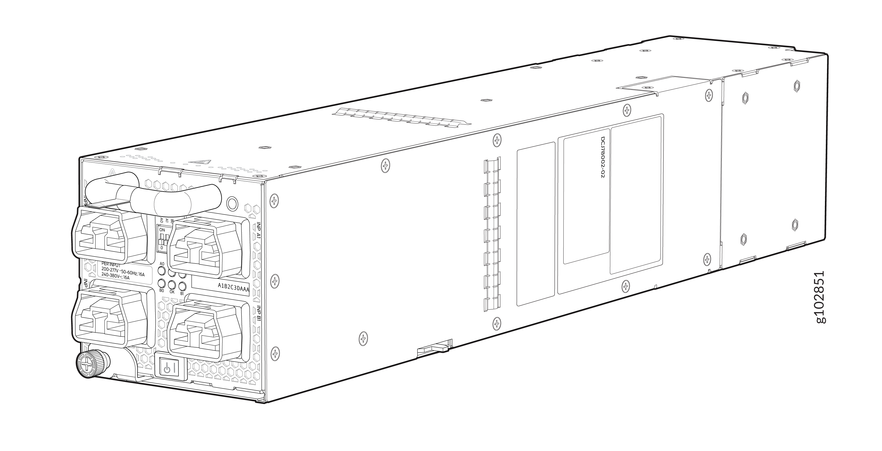
The JNP10K-PWR-AC3 power supply is a high-capacity model that is designed to support AC systems in a 15-A and 20-A mode; see Figure 1.
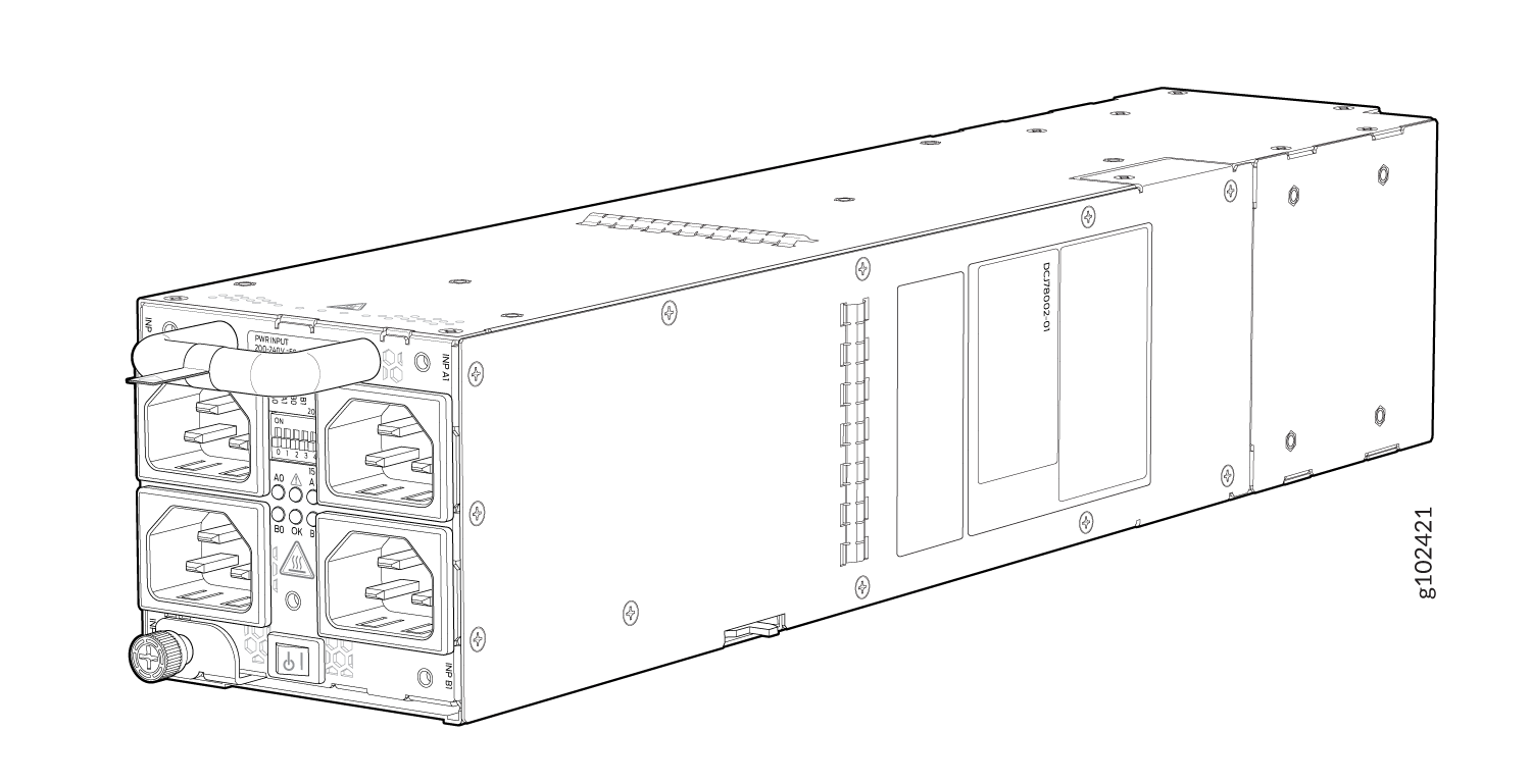
Input—The power supply takes four single-phase AC (180-264 VAC) inputs (A0, A1, B0, and B1) at either 20 A or 15 A and provides a DC output of 12.3V. The input receptacle on the AC power supply unit (PSU) is IEC 320-C22. The mating connector on the power cord is IEC 320-C21.
Output—The power supply provides DC output of 12.3V at:
-
7800 W (20-A input) with three or four active feeds, or
-
6000 W (20-A input) with two active feeds (one source to either A0 or A1, and second source to either B0 or B1), or
-
3000 W (20-A input) with single active feed, or
-
7800 W (15-A input) with four active feeds, or
-
6900 W (15-A input) with three active feeds, or
-
4600 W (15-A input) with two active feeds, or
-
2300 W (15-A input) with single active feed.
-
The operating input voltage range is 180 to 264 VAC for AC systems. The DC output is 12.3 VDC.
-
The number of power feeds and whether the power supplies provide high-output (20-A) or low-output (15-A) power are configured using a set of dual inline package (DIP) switches on the faceplate of the power supply. If one power supply in the chassis is set to low power, the power budget for the chassis is reduced to low power, regardless of their DIP switch settings or the output results in the CLI. This design safeguards against accidentally setting the power supply to 20 A in a facility that can provide only 15 A and tripping the facility circuit breaker. We recommend that you don’t mix DIP switch settings in your system. See Table 2 for information about the input and output voltages when you use the DIP switches.
-
The JNP10K-PWR-AC3 power supply has an ENABLE switch on the front panel to enable/disable the main 12.3 VDC output and +5.0 V_BIAS standby output as well. If the switch is in DISABLE position, the front-end PFC will be disabled to minimize power consumption. This switch has the highest priority over any other shutdown method.
-
The efficiency is 93% at full load. Power factor is 0.98. The maximum inrush current is 50 A for the active feed.
JNP10K-PWR-BLN3 or Active Blank
Juniper Networks offers an Active Blank Power Module (ABPM), JNP10K-PWR-BLN3. This helps in airflow and cooling in the chassis. You can have the following combination of ABPM, passive blank, and JNP10K-PWR-AC3 power supply units (PSU) in the router chassis:
-
Three PSUs
-
Two PSUs with one ABPM
-
One PSU with one ABPMs and one passive blank
-
One PSU with two ABPMs
-
Table 1: PSU, ABPM, Passive Blank Matrix JNP10K-PWR-AC3 PSU(s)
ABPM (JNP10K-PWR-BLN3)
Passive Blank
3
-
-
2
1
-
1
1
1
1
2
-
Note:A minimum of one JNP10K-PWR-AC3 power supply unit (PSU) must be present in the router chassis.
The JNP10K-PWR-AC3 power supply has internal fans that contribute to chassis cooling. Three PSUs or two PSUs along with a ABPM must be present in a running chassis to have the adequate airflow. While the minimum power supplies are required to be present in the chassis, they all need not be necessarily connected to power source. If a power supply is installed in a slot but not connected to a power source, it draws power from the chassis to power the internal fans in the power supplies.
Extreme burn danger—The JNP10K-PWR-AC3 can reach temperatures in the range of 158°F to 176°F (70°C to 80°C) under running conditions.
The router is pluggable type A equipment installed in a restricted-access location. It has a separate protective earthing terminal on the chassis that must be connected to earth ground permanently to ground the chassis adequately and protect the operator from electrical hazards.
Before you begin installing the router, ensure that a licensed electrician has attached an appropriate grounding lug to the grounding cable that you supply. Using a grounding cable with an incorrectly attached lug can damage the router.
Use a 2-pole circuit breaker rated at 25 A in the building installation and the system, or as per local electrical code.
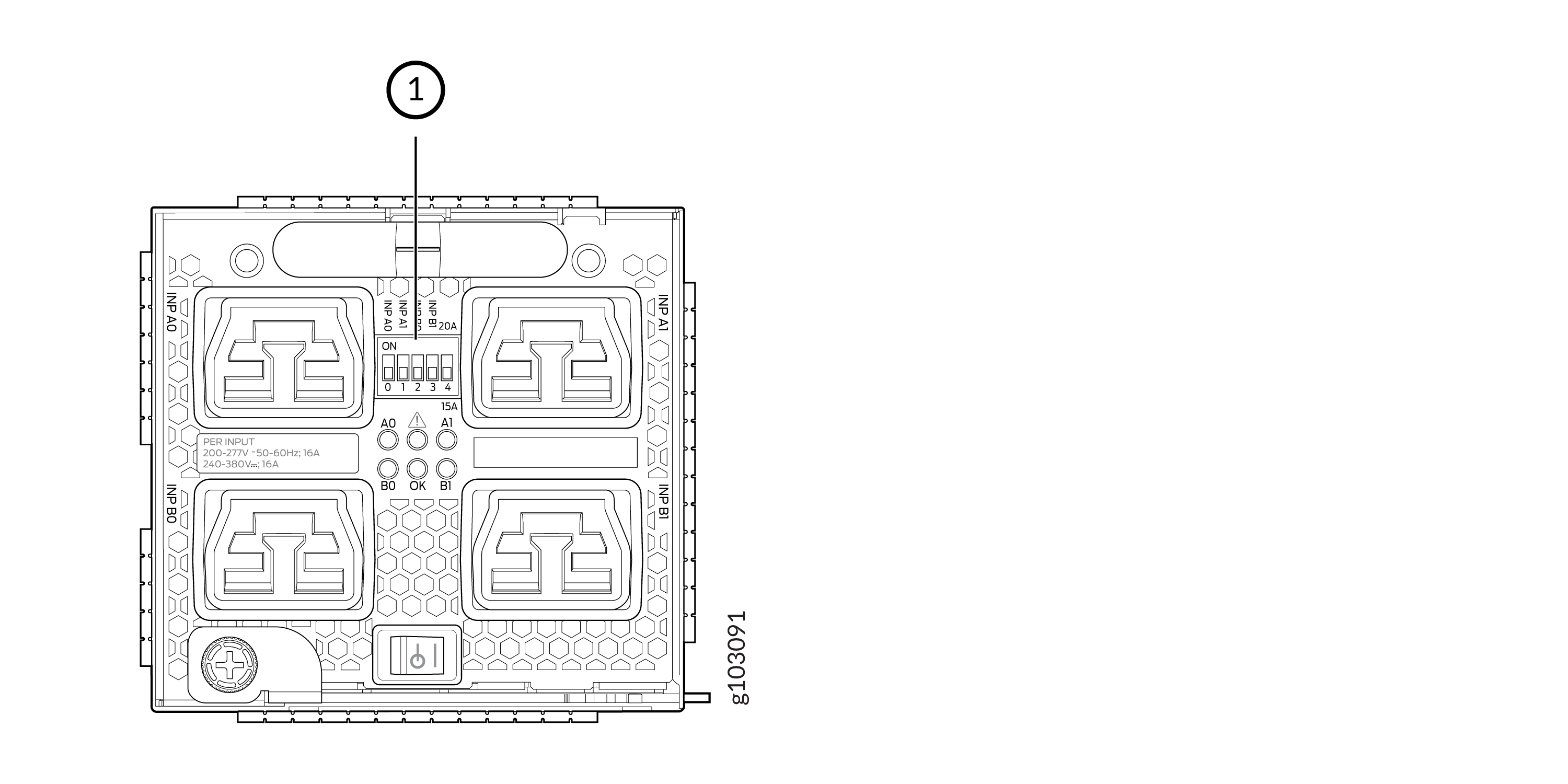
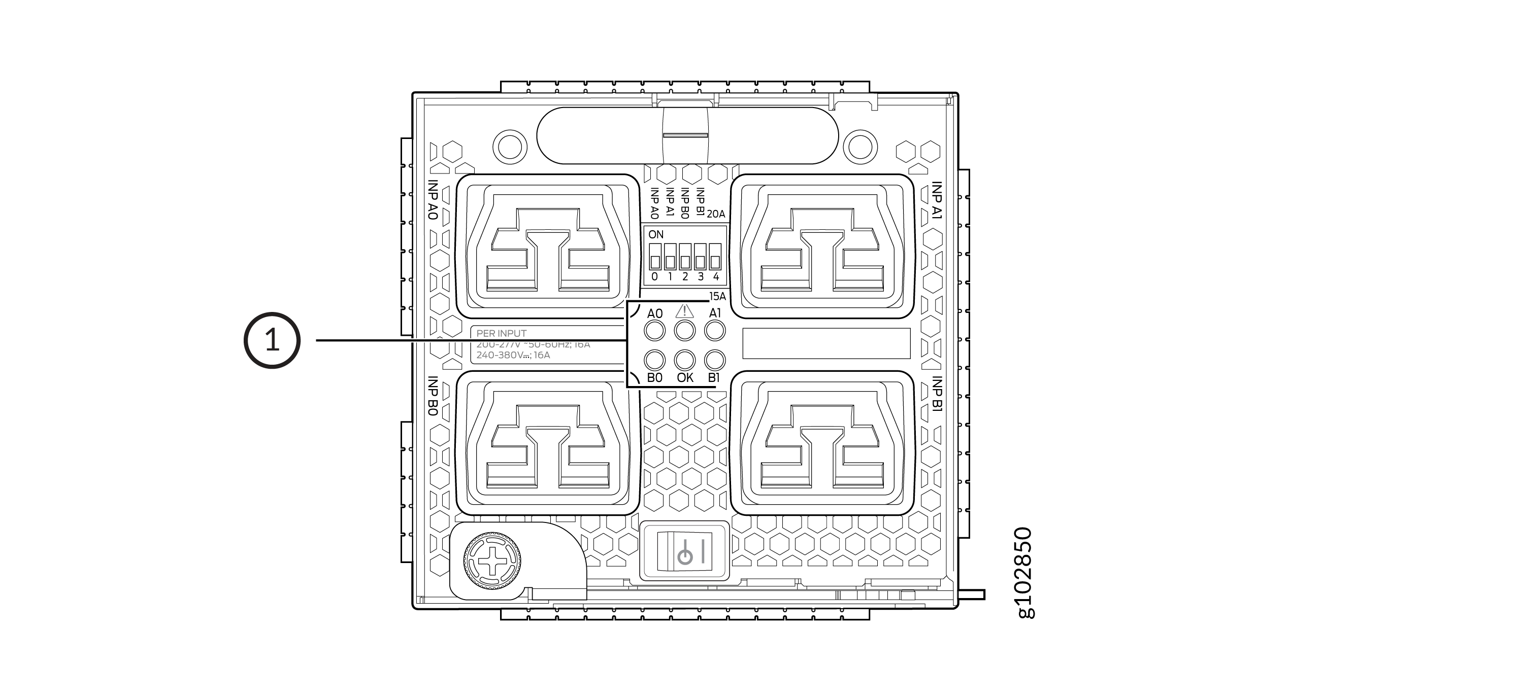
The JNP10K-PWR-AC3 Power Supplies have five dual position DIP switches (INP-A0, INP-A1, INP-B0, INP-B1, and DIP4) that are accessible from the front panel. DIP4 is the fifth DIP switch, which is used to indicate whether 20A or 15A input source is connected. See Figure 2 and Table 2 to know the layout of the DIP switches and the power output when the DIP switches are set in different combinations.
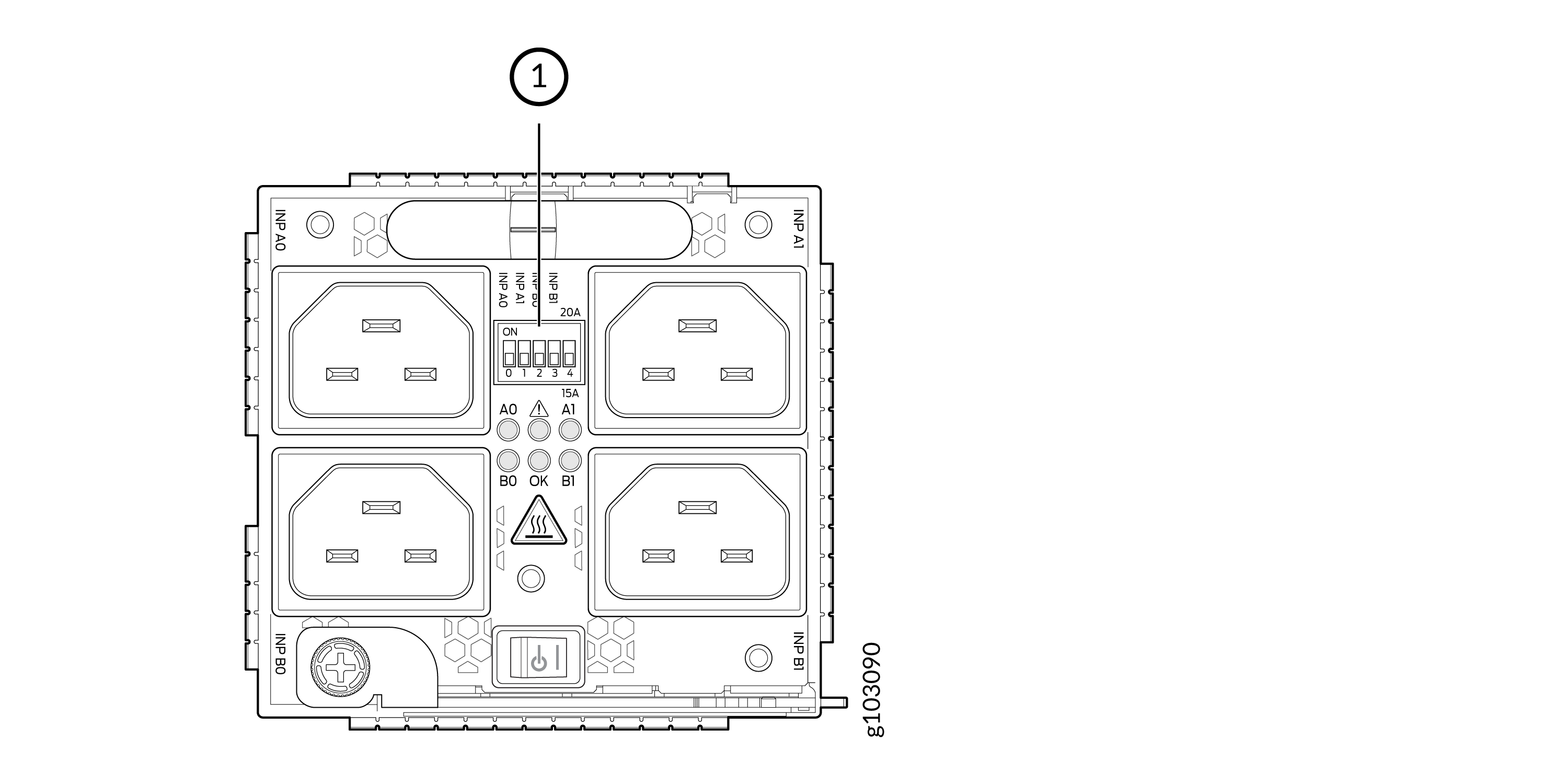
1— DIP switches
|
INP-A0 (Switch 0) |
INP-A1 (Switch 1) |
INP-B0 (Switch 2) |
INP-B1 (Switch 3) |
Switch 4 (High Input 20 A/Low Input 15 A) |
Output Power |
|---|---|---|---|---|---|
|
15-A |
|||||
|
Off |
Off |
Off |
On |
Off (15 A) |
2300 W |
|
Off |
Off |
On |
Off |
Off (15 A) |
2300 W |
|
Off |
Off |
On |
On |
Off (15 A) |
4600 W |
|
Off |
On |
Off |
Off |
Off (15 A) |
2300 W |
|
Off |
On |
Off |
On |
Off (15 A) |
4600 W |
|
Off |
On |
On |
On |
Off (15 A) |
6900 W |
|
Off |
On |
On |
Off |
Off (15 A) |
4600 W |
|
On |
Off |
Off |
Off |
Off (15 A) |
2300 W |
|
On |
Off |
Off |
On |
Off (15 A) |
4600 W |
|
On |
Off |
On |
Off |
Off (15 A) |
4600 W |
|
On |
Off |
On |
On |
Off (15 A) |
6900 W |
|
On |
On |
Off |
Off |
Off (15 A) |
4600 W |
|
On |
On |
Off |
On |
Off (15 A) |
6900 W |
|
On |
On |
On |
Off |
Off (15 A) |
6900 W |
|
On |
On |
On |
On |
Off (15 A) |
7800 W |
|
20-A |
|||||
|
Off |
Off |
Off |
On |
On (20 A) |
3000 W |
|
Off |
Off |
On |
Off |
On (20 A) |
3000 W |
|
Off |
Off |
On |
On |
On (20 A) |
6000 W |
|
Off |
On |
Off |
Off |
On (20 A) |
3000 W |
|
Off |
On |
Off |
On |
On (20 A) |
6000 W |
|
Off |
On |
On |
Off |
On (20 A) |
6000 W |
|
Off |
On |
On |
On |
On (20 A) |
7800 W |
|
On |
Off |
Off |
Off |
On (20 A) |
3000 W |
|
On |
Off |
Off |
On |
On (20 A) |
6000 W |
|
On |
Off |
On |
Off |
On (20 A) |
6000 W |
|
On |
Off |
On |
On |
On (20 A) |
7800 W |
|
On |
On |
Off |
Off |
On (20 A) |
6000 W |
|
On |
On |
Off |
On |
On (20 A) |
7800 W |
|
On |
On |
On |
Off |
On (20 A) |
7800 W |
|
On |
On |
On |
On |
On (20 A) |
7800 W |
It is important to connect the input feeds of the JNP10K-PWR-AC3 power supply to AC mains before powering-on the router.
JNP10K-PWR-AC3 Power Supply LEDs
The JNP10K-PWR-AC3 power supply has six LEDs on its faceplate: !, OK, A0, A1, B0, and B1. The numbered LEDs correspond to the four inputs (INP-A0, INP-A1, INP-B0, and INP-B1). Additionally, there are two more LEDs OK (Power OK) and !(Fault). These LEDs display information about the status of the power supply. See Figure 3.
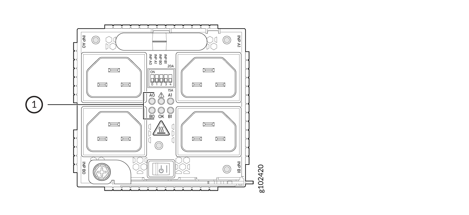
1—LEDs on the JNP10K-PWR-AC3 Power Supply denoting:
-
! Fault
-
OK Power OK
-
A0 INP A0–Source input 1
-
A1 INP A1–Source input 2
-
B0 INP B0–Source input 3
-
B1 INP B1–Source input 4
Physical markings on the power supply are INP-A0,
INP-A1, INP-B0, and
INP-B1. These markings correspond to INP-A0, INP-A1, INP-B0, and
INP-B1 in the show chassis power output (see Table 3).
|
Physical Marking on JNP10K-PWR-AC3 |
Corresponding Physical LED Marking |
show chassis power Command |
|---|---|---|
|
INP A0 |
A0 |
INP-A0 |
|
INP A1 |
A1 |
INP-A1 |
|
INP B0 |
B0 |
INP-B0 |
|
INP B1 |
B1 |
INP-B1 |
Table 4 describes the LEDs on a JNP10K-PWR-AC3 power supply, color on the LED, state, and its meaning.
|
LED |
Color |
State |
Description |
|---|---|---|---|
|
A0 |
Yellow |
Solid |
One of the following:
|
|
Green |
Solid |
The power supply is functioning properly. |
|
|
A1 |
Yellow |
Solid |
One of the following:
|
|
Green |
Solid |
The power supply is functioning properly. |
|
|
B0 |
Yellow |
Solid |
One of the following:
|
|
Green |
Solid |
The power supply is functioning properly. |
|
|
B1 |
Yellow |
Solid |
One of the following:
|
|
Green |
Solid |
The power supply is functioning properly. |
|
|
OK (Power OK) |
Green |
Solid |
The power supply is functioning properly. |
| Green | Blinking |
The power supply is functioning properly but there is a mismatch in the corresponding DIP switch. Example: If A0 is receiving input power but the corresponding DIP switch 0 is not ON, then the LED will blink green. |
|
|
Yellow |
Blinking |
The power supply output has detected a fault. |
|
|
Unlit |
Off |
The power supply is switched off. |
|
|
! (Fault) |
Red |
Solid |
The power supply has failed and must be replaced. |
|
Unlit |
Off |
The power supply is functioning normally. |
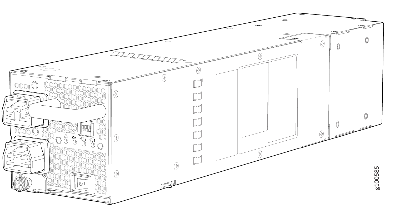
JNP10K-PWR-AC2 Power Supply
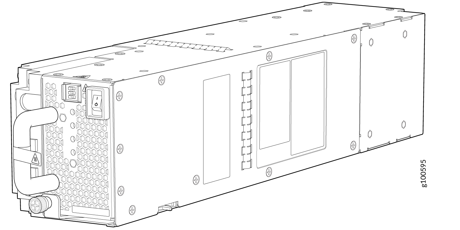
The JNP10K-PWR-AC2 power supply is a high-capacity model that is designed to support AC, high-voltage AC (HVAC), or high-voltage DC (HVDC) systems in either a 20-A or a 30-A mode; see Figure 4. The power supply feeds AC input and provides DC output of 5000 W with a single feed and 5500 W with a dual feed. The operating input voltage range is 180 to 305 VAC for AC systems and 190 to 410 VDC for DC systems.
The number of power feeds and whether the power supplies provide high-output (30-A) or low-output (20-A) power are configured using a set of dual inline package (DIP) switches on the faceplate of the power supply. If one power supply in the chassis is set to low power, the power budget for the chassis is reduced to low power, regardless of their DIP switch settings or the output results in the CLI. This design safeguards against accidentally setting the power supply to 30 A in a facility that can provide only 20 A and tripping the facility circuit breaker. We recommend that you don’t mix DIP switch settings in your system. See Table 5 for information about the input and output voltages when you use the DIP switches.
Extreme burn danger—Do not handle an HVAC or HVDC power supply running in the chassis without heat protective gloves. The JNP10K-PWR-AC2 can reach temperatures in the range of 158°F to 176°F (70°C to 80°C) under running conditions.
The router is pluggable type A equipment installed in a restricted-access location. It has a separate protective earthing terminal on the chassis that must be connected to earth ground permanently to ground the chassis adequately and protect the operator from electrical hazards.
Before you begin installing the router, ensure that a licensed electrician has attached an appropriate grounding lug to the grounding cable that you supply. Using a grounding cable with an incorrectly attached lug can damage the router.
Use a 2-pole circuit breaker rated at 25 A in the building installation and the system, or as per local electrical code.
|
INP0—PS 0(DIP Switch 1) |
INP1—PS 1(DIP Switch 2) |
H/L (High Input 30 A/Low Input 20 A) |
Output Power |
|---|---|---|---|
|
On |
On |
On (30 A) |
5500 W |
|
On |
On |
Off (20 A) |
3000 W |
|
On |
Off |
On (30 A) |
5000 W |
|
Off |
On |
On (30 A) |
5000 W |
|
On |
Off |
Off (20 A) |
2700 W |
|
Off |
On |
Off (20 A) |
2700 W |
If one of the DIP switches is in the on position and if the power switch is set to the off position, the system raises an alarm that the input feeds are missing. You can avoid this by setting both the DIP switches to off position.
- IP1
- INP1 in the CLI output for Junos OS Evolved Release 20.4R2 or later.
- INP0 in the CLI output for releases earlier than Junos OS Evolved Release 20.4R2.
- IP2
- INP2 in the CLI output for Junos OS Evolved Release 20.4R2 or later.
- INP1 in the CLI output for releases earlier than Junos OS Evolved Release 20.4R2.
It is important to connect both input feeds of the JNP10K-PWR-AC2 power supply to AC mains before loading the system with power.
The power supplies have internal fans that contribute to chassis cooling. Therefore, all the power supplies must be present in a running chassis to have the adequate airflow. While all power supplies are required to be present in the chassis, they do not necessarily be connected to power. If a power supply is installed in a slot but is not connected to a power source, it draws power from the chassis to power the internal fans in the power supplies.
JNP10K-PWR-AC2 Power Supply LEDs
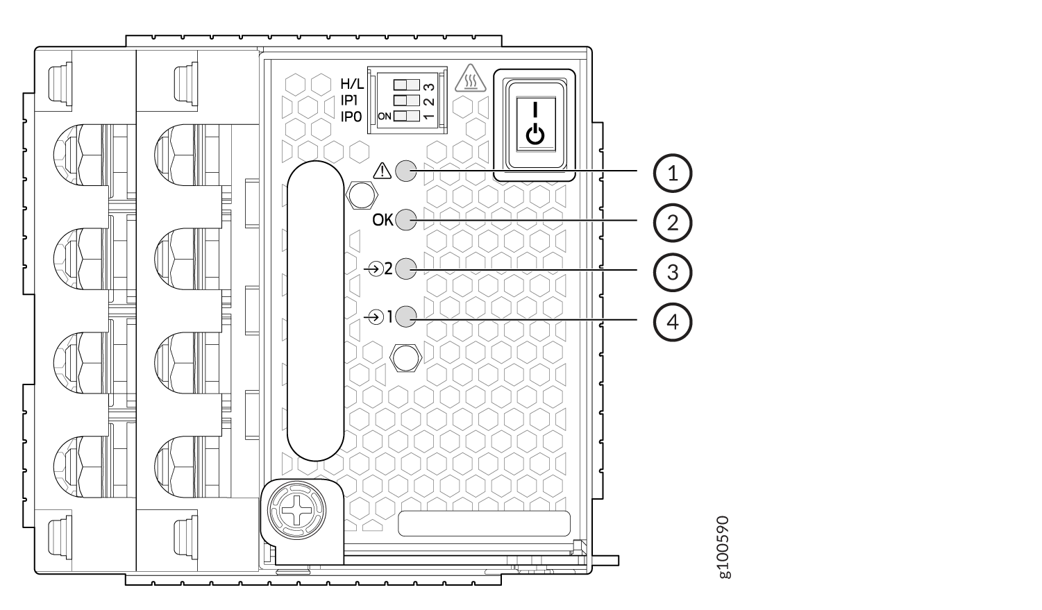
The JNP10K-PWR-AC2 power supply has four LEDs on its faceplate: !, OK, 2, and 1. These LEDs display information about the status of the power supply. See Figure 5.
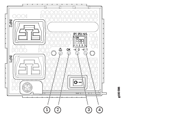
1 — ! Fault | 3 — 2 INP2–Source input 1 |
2 — OK Power OK | 4 — 1 INP1–Source input 0 |
Physical markings on the power supply are 1 and
2. These markings correspond to INP0 and INP1 in the show
chassis power output (see Table 6).
|
Physical Marking on JNP10K-PWR-AC2 |
show chassis power Command |
|---|---|
|
1 |
INP0 |
|
2 |
INP1 |
Table 7 describes the LEDs on a JNP10K-PWR-AC2 power supply.
|
LED |
Color |
State |
Description |
|---|---|---|---|
|
1 (or |
Yellow |
Solid |
One of the following:
|
|
Green |
Solid |
The power supply is functioning properly. |
|
|
2 (or |
Yellow |
Solid |
One of the following:
|
|
Green |
Solid |
The power supply is functioning properly. |
|
|
OK (Power OK) |
Green |
Solid |
The power supply is functioning properly. |
|
Yellow |
Blinking |
The power supply output has detected a fault. |
|
|
Unlit |
Off |
The power supply is switched off. |
|
|
! (Fault) |
Red |
Solid |
The power supply has failed and must be replaced. |
|
Unlit |
Off |
The power supply is functioning normally. |
JNP10K-PWR-DC3 Power Supply
The JNP10K-PWR-DC3 power supply is a high-capacity model designed to support four power supplies in a single housing that accepts either 60 A or 80 A from four input power feeds.
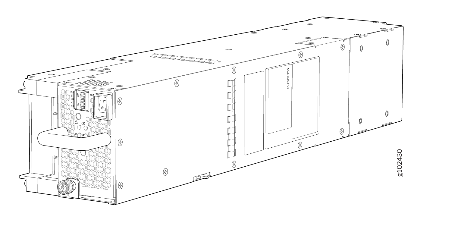
The JNP10K-PWR-DC3 power supply has an ON/Standby switch on the front panel to enable or disable the main 12.3 VDC output and +5.0 V_BIAS standby output.
The number of power feeds and whether the power supplies provide high input of 80 A or low input of 60 A are configured using the dual inline package (DIP) switches on the front panel of the power supply. The JNP10K-PWR-DC3 power supplies have five dual-position DIP switches. DIP0 through DIP3 switches (INP-A0, INP-A1, INP-B0, INP-B1) indicates whether the input is connected to the source. DIP4 (fifth DIP switch) indicate whether an 80 A or 60 A input source is connected. See Figure 7 for the layout of the DIP switches, and Table 8 for information on the power output when the DIP switches are set in different combinations.
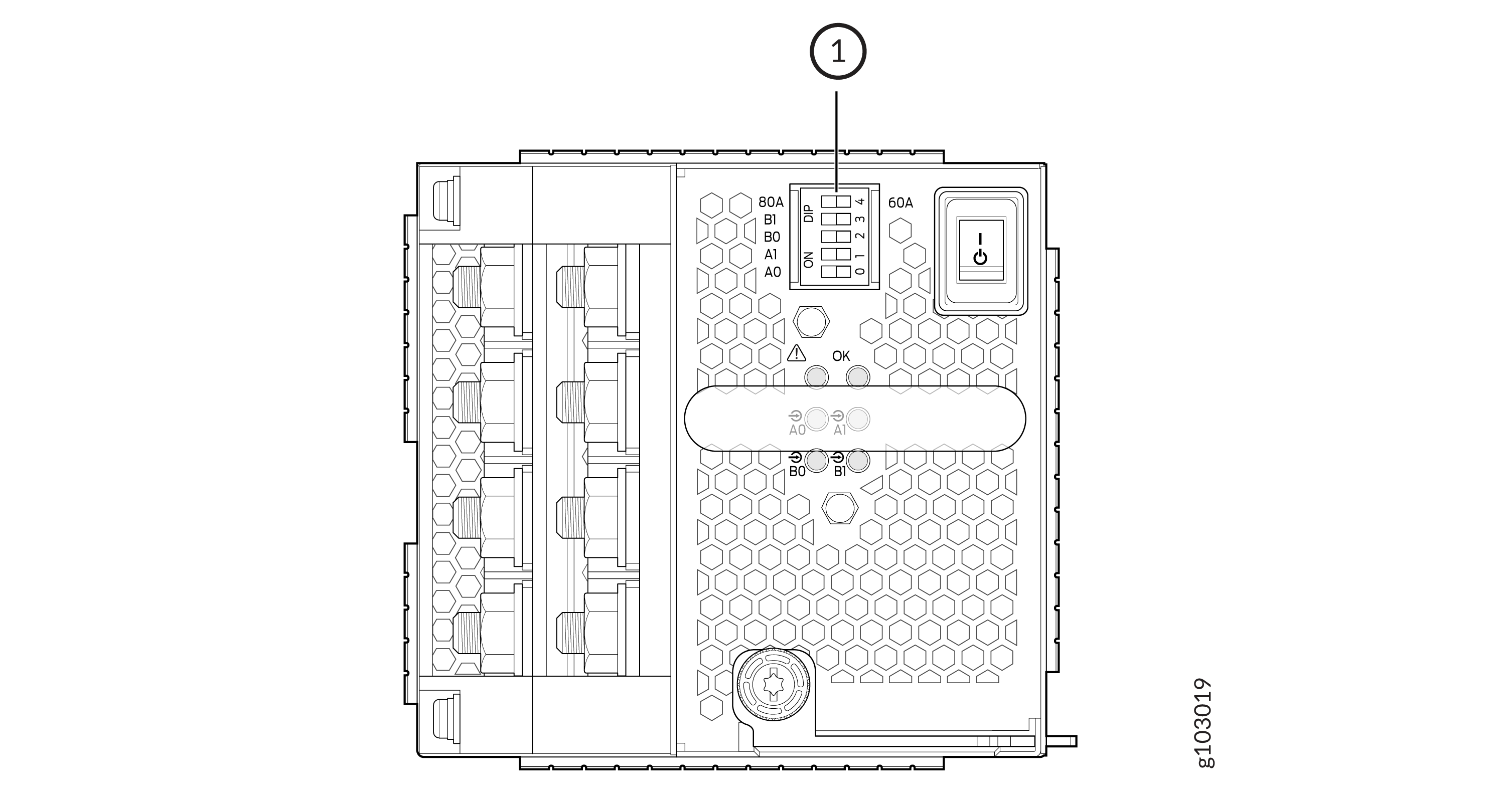
1 — DIP Switches |
|
INP-A0 (Switch 0) |
INP-A1 (Switch 1) |
INP-B0 (Switch 2) |
INP-B1 (Switch 3) |
Switch 4 (Low Input 60 A/ High Input 80 A) |
Output Power |
|---|---|---|---|---|---|
|
60 A |
|||||
|
Off |
Off |
Off |
On |
Off (60 A) |
2200 W |
|
Off |
Off |
On |
Off |
Off (60 A) |
2200 W |
|
Off |
Off |
On |
On |
Off (60 A) |
4400 W |
|
Off |
On |
Off |
Off |
Off (60 A) |
2200 W |
|
Off |
On |
Off |
On |
Off (60 A) |
4400 W |
|
Off |
On |
On |
Off |
Off (60 A) |
4400 W |
|
Off |
On |
On |
On |
Off (60 A) |
6600 W |
|
On |
Off |
Off |
Off |
Off (60 A) |
2200 W |
|
On |
Off |
Off |
On |
Off (60 A) |
4400 W |
|
On |
Off |
On |
Off |
Off (60 A) |
4400 W |
|
On |
Off |
On |
On |
Off (60 A) |
6600 W |
|
On |
On |
Off |
Off |
Off (60 A) |
4400 W |
|
On |
On |
Off |
On |
Off (60 A) |
6600 W |
|
On |
On |
On |
Off |
Off (60 A) |
6600 W |
|
On |
On |
On |
On |
Off (60 A) |
7800 W |
|
80 A |
|||||
|
Off |
Off |
Off |
On |
On (80 A) |
3000 W |
|
Off |
Off |
On |
Off |
On (80 A) |
3000 W |
|
Off |
Off |
On |
On |
On (80 A) |
6000 W |
|
Off |
On |
Off |
Off |
On (80 A) |
3000 W |
|
Off |
On |
Off |
On |
On (80 A) |
6000 W |
|
Off |
On |
On |
Off |
On (80 A) |
6000 W |
|
Off |
On |
On |
On |
On (80 A) |
7800 W |
|
On |
Off |
Off |
Off |
On (80 A) |
3000 W |
|
On |
Off |
Off |
On |
On (80 A) |
6000 W |
|
On |
Off |
On |
Off |
On (80 A) |
6000 W |
|
On |
Off |
On |
On |
On (80 A) |
7800 W |
|
On |
On |
Off |
Off |
On (80 A) |
6000 W |
|
On |
On |
Off |
On |
On (80 A) |
7800 W |
|
On |
On |
On |
Off |
On (80 A) |
7800 W |
|
On |
On |
On |
On |
On (80 A) |
7800 W |
Active Blank (JNP10K-PWR-BLN3)
Juniper Networks offers the JNP10K-PWR-BLN3, which is an Active Blank Power Module (ABPM). This helps in airflow and cooling in the chassis in the absence of a power supply unit (PSU). You can configure the router chassis with a combination of ABPM and JNP10K-PWR-DC3 PSUs:
|
JNP10K-PWR-DC3 PSU(s) |
JNP10K-PWR-BLN3 ABPM |
|---|---|
|
3 |
- |
|
2 |
1 |
|
1 |
2 |
A minimum of one JNP10K-PWR-DC3 PSU must be present in the router chassis.
The JNP10K-PWR-DC3 power supply has internal fans that contribute to chassis cooling. Three PSUs or two PSUs along with an ABPM must be present in a running chassis to have the adequate airflow. Minimum power supplies must be present in the chassis but all of them need not be connected to power source. If a power supply is installed in a slot but not connected to a power source, it draws power from the chassis to power the internal fans in the power supplies.
The router is pluggable type A equipment installed in a restricted-access location. It has a separate protective earthing terminal on the chassis that must be connected to earth ground permanently to ground the chassis adequately and protect the operator from electrical hazards.
Before you begin installing the router, ensure that a licensed electrician has attached an appropriate grounding lug to the grounding cable that you supply. Using a grounding cable with an incorrectly attached lug can damage the router.
JNP10K-PWR-DC3 Power Supply LEDs
The JNP10K-PWR-DC3 power supply has six LEDs on its faceplate. LEDs A0, A1, B0, and B1 correspond to the four input sources (INP-A0, INP-A1, INP-B0, INP-B1). There are two additional LEDs: OK (Power OK) and ! (indicating a fault). These LEDs display information on the status of the power supply. See Figure 8.
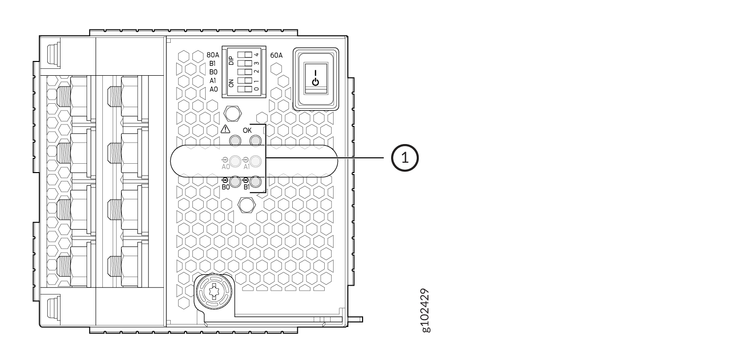
1 — LEDs on the JNP10K-PWR-DC3:
|
|
LED Labels on JNP10K-PWR-DC3 |
Output of |
|---|---|
|
A0 |
INP-A0 |
|
A1 |
INP-A1 |
|
B0 |
INP-B0 |
|
B1 |
INP-B1 |
|
LED |
Color |
State |
Description |
|---|---|---|---|
|
A0 ( |
Amber |
Blinking |
The input voltage at A0 is present but not within the operational range. |
|
Green |
Solid |
The input voltage at A0 is present and functioning within the operational range. |
|
|
Unlit |
Off |
No input. |
|
|
A1 ( |
Amber |
Blinking |
The input voltage at A1 is present but not within the operational range. |
|
Green |
Solid |
The input voltage at A1 is present and functioning within the operational range. |
|
|
Unlit |
Off |
No input. |
|
|
B0 ( |
Amber |
Blinking |
The input voltage at B0 is present but not within the operational range. |
|
Green |
Solid |
The input voltage at B0 is present and functioning within the operational range. |
|
|
Unlit |
Off |
No input. |
|
|
B1 ( |
Amber |
Blinking |
The input voltage at B1 is present but not within the operational range. |
|
Green |
Solid |
The input voltage at B1 is present and functioning within the operational range. |
|
|
Unlit |
Off |
No input. |
|
|
OK (Power OK) |
Unlit |
Off |
The power supply output is not within the specified limits. |
|
Green |
Solid |
The power supply output voltage is functioning within the specified limits. |
|
|
! (Fault) |
Red |
Solid |
One of the following:
|
|
Unlit |
Off |
The power supply is functioning properly. |
JNP10K-PWR-DC2 Power Supply
The JNP10K-PWR-DC2 power supply provides two power supplies in a single housing that accepts either 60 A or 80 A using four redundant input power feeds. See Figure 9.
The two internal power supplies (PS 0 and PS 1) each have redundant input feeds: A0 and/or B0 provide power to PS 0 and A1 and/or B1 provide power to PS 1.The input feed A0 or B0 with the highest input voltage provides power to PS 0. Similarly, the input feed A1 or B1 with the highest input voltage provides power to PS 1. A0, B0, A1, and B1 share the power if the input voltage is the same. You configure the input using a set of three DIP switches on the power supply faceplate that sets the combined output power for both internal power supplies. The output depends on the settings of these DIP switches. See Table 12. The output of the PS 0 and PS 1 shares the output power.
|
INP0—PS 0(DIP Switch 1) |
INP1—PS 1(DIP Switch 2) |
H/L (High Input 80 A/Low Input 60 A) |
Output Power |
|---|---|---|---|
|
On |
On |
On (80 A) |
5500 W |
|
On |
On |
Off (60 A) |
4400 W |
|
On |
Off |
On (80 A) |
2750 W |
|
Off |
On |
On (80 A) |
2750 W |
|
On |
Off |
Off (60 A) |
2200 W |
|
Off |
On |
Off (60 A) |
2200 W |
A combined output of 5500 W with PS 0 and PS 1 active is available at 56 VDC or greater. If the input voltage is less than 56 VDC, the output power decreases linearly, keeping the input current a little below the default 60 A. However, the power supply supports 5500 W at lower input voltage if you provide 80 A and sets the power supply switch to 80 A setting.
A combined output of 2750 W with only PS 0 or PS 1 active is available at 56 VDC or greater. If the input voltage is less than 56 VDC, the output power decreases linearly, keeping the input current a little below the default 60 A. However, the power supply supports 2750 W at lower input voltage if you provide 80 A and sets the power supply switch to 80 A setting.
The JNP10K-PWR-DC2 power supply requires a dedicated circuit breaker for each input DC feed. You must use a circuit breaker that is rated for 80 A DC with medium delay.
The power supplies have internal fans that contribute to chassis cooling. Therefore, all the power supplies must be present in a running chassis to have the adequate airflow. While all power supplies are required to be present in the chassis, they do not necessarily be connected to power. If a power supply is installed in a slot but is not connected to a power source, it draws power from the chassis to power the internal fans in the power supplies.
The router is pluggable type A equipment installed in a restricted-access location. It has a separate protective earthing terminal on the chassis that must be connected to earth ground permanently to ground the chassis adequately and protect the operator from electrical hazards.
Before you begin installing the router, ensure that a licensed electrician has attached an appropriate grounding lug to the grounding cable that you supply. Using a grounding cable with an incorrectly attached lug can damage the router.
JNP10K-PWR-DC2 Power Supply LEDs
A JNP10K-PWR-DC2 power supply has four LEDs on its faceplate: 1, 2, OK, and the symbol for fault, !. These LEDs display information about the status of the power supply. See Figure 10.
1 — ! Fault | 3 — 2 Power source input 1 |
2 — OK Power OK | 4 — 1 Power source input 0 |
Table 13 describes the LEDs on a JNP10K-PWR-DC2 power supply.
|
LED |
Color |
State |
Description |
|---|---|---|---|
|
1 ( |
Green |
Solid |
The DC power is within normal operating range (—40 VDC to —72 VDC). |
|
Yellow |
Blinking |
The DC power input voltage is not within normal operating range. |
|
|
Unlit |
Off |
The power supply is switched off. |
|
|
OK (Power OK) |
Green |
Solid |
The DC power output is within normal operating range. |
|
Yellow |
Blinking |
The power supply output is out of the power limits. |
|
|
! (Fault) |
Red |
Solid |
The power supply has failed and must be replaced. |
|
Unlit |
Off |
The power supply is functioning normally. Or, only one input is powered and the enable switch for the input that is not powered is set to ON. See Install a JNP10K-PWR-DC2 Power Supply for more information about the enable switches. |
If the 1 or 2 and the OK LED are unlit, the power cables are not installed properly or the power supply has failed.
If the 1 or 2 LED is lit green and the OK LED is unlit, the power supply is not installed properly or the power supply has an internal failure.
If the ! LED is blinking, add a power supply to balance the power demand and supply.
JNP10K-PWR-AC3H Power Supply
The JNP10K-PWR-AC3H power supply unit is a high-capacity model that is designed to support HVAC or HVDC systems in a 15-A and 20-A mode; see Figure 11. The power supply unit detects whether the input power is AC or DC automatically.
Input—The power supply unit takes four single-phase HVAC (180-305 VAC) or HVDC (190 - 410VDC) inputs (A0, A1, B0, and B1) at either 20 A or 15 A and provides a DC output of 12.3V. The input receptacle on the AC power supply unit (PSU) is IEC 320-C22. The mating connector on the power cord is IEC 320-C21.
Output—The power supply provides DC output of 12.3V at:
-
7800 W (20-A input) with three or four active feeds, or
-
6000 W (20-A input) with two active feeds (one source to either A0 or A1, and second source to either B0 or B1), or
-
3000 W (20-A input) with single active feed, or
-
7800 W (15-A input) with four active feeds, or
-
6900 W (15-A input) with three active feeds, or
-
4600 W (15-A input) with two active feeds, or
-
2300 W (15-A input) with single active feed.
-
The operating input voltage range is 180 to 264 VAC for AC systems. The DC output is 12.3 VDC.
-
The number of power feeds and whether the power supplies provide high-output (20-A) or low-output (15-A) power are configured using a set of dual inline package (DIP) switches on the faceplate of the power supply. If one power supply in the chassis is set to low power, the power budget for the chassis is reduced to low power, regardless of their DIP switch settings or the output results in the CLI. This design safeguards against accidentally setting the power supply to 20 A in a facility that can provide only 15 A and tripping the facility circuit breaker. We recommend that you don’t mix DIP switch settings in your system. See Table 2 for information about the input and output voltages when you use the DIP switches.
-
The JNP10K-PWR-AC3H power supply has an ENABLE switch on the front panel to enable/disable the main 12.3 VDC output and +5.0 V_BIAS standby output as well. If the switch is in DISABLE position, the front-end PFC will be disabled to minimize power consumption. This switch has the highest priority over any other shutdown method.
-
The Power Factor Correction (PFC) is PF 0.98 kW minimum at full load. The maximum inrush current is 50 A for the active feed.
JNP10K-PWR-BLN3 or Active Blank
Juniper Networks offers an Active Blank Power Module (ABPM), JNP10K-PWR-BLN3. This helps in airflow and cooling in the chassis. You can have the following combination of ABPM, passive blank, and JNP10K-PWR-AC3H power supply units (PSU) in the router chassis:
-
Three PSUs
-
Two PSUs with one ABPM
-
One PSU with one ABPMs and one passive blank
-
One PSU with two ABPMs
-
Table 14: PSU, ABPM, Passive Blank Matrix JNP10K-PWR-AC3H PSU(s)
ABPM (JNP10K-PWR-BLN3)
Passive Blank
3
-
-
2
1
-
1
1
1
1
2
-
Note:A minimum of one JNP10K-PWR-AC3H power supply unit (PSU) must be present in the router chassis.
The JNP10K-PWR-AC3H power supply has internal fans that contribute to chassis cooling. Three PSUs or two PSUs along with a ABPM must be present in a running chassis to have the adequate airflow. While the minimum power supplies are required to be present in the chassis, they all need not be necessarily connected to power source. If a power supply is installed in a slot but not connected to a power source, it draws power from the chassis to power the internal fans in the power supplies.
Extreme burn danger—The JNP10K-PWR-AC3H can reach temperatures in the range of 158°F to 176°F (70°C to 80°C) under running conditions.
The router is pluggable type A equipment installed in a restricted-access location. It has a separate protective earthing terminal on the chassis that must be connected to earth ground permanently to ground the chassis adequately and protect the operator from electrical hazards.
Before you begin installing the router, ensure that a licensed electrician has attached an appropriate grounding lug to the grounding cable that you supply. Using a grounding cable with an incorrectly attached lug can damage the router.
Use a 2-pole circuit breaker rated at 25 A in the building installation and the system, or as per local electrical code.
The JNP10K-PWR-AC3H Power Supplies have five dual position DIP switches (INP-A0, INP-A1, INP-B0, INP-B1, and DIP4) that are accessible from the front panel. DIP4 is the fifth DIP switch, which is used to indicate whether 20A or 15A input source is connected. See Figure 12 and Table 15 to know the layout of the DIP switches and the power output when the DIP switches are set in different combinations.
1—DIP switches
|
INP-A0 (Switch 0) |
INP-A1 (Switch 1) |
INP-B0 (Switch 2) |
INP-B1 (Switch 3) |
Switch 4 (High Input 20 A/Low Input 15 A) |
Output Power |
|---|---|---|---|---|---|
|
15-A |
|||||
|
Off |
Off |
Off |
On |
Off (15 A) |
2300 W |
|
Off |
Off |
On |
Off |
Off (15 A) |
2300 W |
|
Off |
Off |
On |
On |
Off (15 A) |
4600 W |
|
Off |
On |
Off |
Off |
Off (15 A) |
2300 W |
|
Off |
On |
Off |
On |
Off (15 A) |
4600 W |
|
Off |
On |
On |
On |
Off (15 A) |
6900 W |
|
Off |
On |
On |
Off |
Off (15 A) |
4600 W |
|
On |
Off |
Off |
Off |
Off (15 A) |
2300 W |
|
On |
Off |
Off |
On |
Off (15 A) |
4600 W |
|
On |
Off |
On |
Off |
Off (15 A) |
4600 W |
|
On |
Off |
On |
On |
Off (15 A) |
6900 W |
|
On |
On |
Off |
Off |
Off (15 A) |
4600 W |
|
On |
On |
Off |
On |
Off (15 A) |
6900 W |
|
On |
On |
On |
Off |
Off (15 A) |
6900 W |
|
On |
On |
On |
On |
Off (15 A) |
7800 W |
|
20-A |
|||||
|
Off |
Off |
Off |
On |
On (20 A) |
3000 W |
|
Off |
Off |
On |
Off |
On (20 A) |
3000 W |
|
Off |
Off |
On |
On |
On (20 A) |
6000 W |
|
Off |
On |
Off |
Off |
On (20 A) |
3000 W |
|
Off |
On |
Off |
On |
On (20 A) |
6000 W |
|
Off |
On |
On |
Off |
On (20 A) |
6000 W |
|
Off |
On |
On |
On |
On (20 A) |
7800 W |
|
On |
Off |
Off |
Off |
On (20 A) |
3000 W |
|
On |
Off |
Off |
On |
On (20 A) |
6000 W |
|
On |
Off |
On |
Off |
On (20 A) |
6000 W |
|
On |
Off |
On |
On |
On (20 A) |
7800 W |
|
On |
On |
Off |
Off |
On (20 A) |
6000 W |
|
On |
On |
Off |
On |
On (20 A) |
7800 W |
|
On |
On |
On |
Off |
On (20 A) |
7800 W |
|
On |
On |
On |
On |
On (20 A) |
7800 W |
It is important to connect the input feeds of the JNP10K-PWR-AC3H power supply to HVAC mains before powering-on the router.
JNP10K-PWR-AC3H Power Supply LEDs
The JNP10K-PWR-AC3H power supply has six LEDs on its faceplate: !, OK, A0, A1, B0, and B1. The numbered LEDs correspond to the four inputs (INP-A0, INP-A1, INP-B0, and INP-B1). Additionally, there are two more LEDs OK (Power OK) and !(Fault). These LEDs display information about the status of the power supply. See Figure 13.
1—LEDs on the JNP10K-PWR-AC3H Power Supply denoting:
-
! Fault
-
OK Power OK
-
A0 INP A0–Source input 1
-
A1 INP A1–Source input 2
-
B0 INP B0–Source input 3
-
B1 INP B1–Source input 4
Physical markings on the power supply are INP-A0,
INP-A1, INP-B0, and
INP-B1. These markings correspond to INP-A0, INP-A1, INP-B0, and
INP-B1 in the show chassis power output (see Table 16).
|
Physical Marking on JNP10K-PWR-AC3H |
Corresponding Physical LED Marking |
show chassis power Command |
|---|---|---|
|
INP A0 |
A0 |
INP-A0 |
|
INP A1 |
A1 |
INP-A1 |
|
INP B0 |
B0 |
INP-B0 |
|
INP B1 |
B1 |
INP-B1 |
Table 17 describes the LEDs on a JNP10K-PWR-AC3H power supply, color on the LED, state, and its meaning.
|
LED |
Color |
State |
Description |
|---|---|---|---|
|
A0 ( |
Yellow |
Solid |
One of the following:
|
|
Green |
Solid |
The power supply is functioning properly. |
|
|
A1 ( |
Yellow |
Solid |
One of the following:
|
|
Green |
Solid |
The power supply is functioning properly. |
|
|
B0 ( |
Yellow |
Solid |
One of the following:
|
|
Green |
Solid |
The power supply is functioning properly. |
|
|
B1 ( |
Yellow |
Solid |
One of the following:
|
|
Green |
Solid |
The power supply is functioning properly. |
|
|
OK (Power OK) |
Green |
Solid |
The power supply is functioning properly. |
| Green | Blinking |
The power supply is functioning properly but there is a mismatch in the corresponding DIP switch. Example: If A0 is receiving input power but the corresponding DIP switch 0 is not ON, then the LED will blink green. |
|
|
Yellow |
Blinking |
The power supply output has detected a fault. |
|
|
Unlit |
Off |
The power supply is switched off. |
|
|
! (Fault) |
Red |
Solid |
The power supply has failed and must be replaced. |
|
Unlit |
Off |
The power supply is functioning normally. |
Fault. Instead, the system keeps the PSM state online and raises an
alarm.