ON THIS PAGE
Install and Remove PTX10004 Line Card Components
Line cards on the PTX10004 are field-replaceable units (FRUs) that can be installed in any of the line-card slots on the front of the chassis. The line cards are hot-insertable and hot-removable: you can remove and replace them without powering off the router or disrupting router functions.
How to Handle and Store PTX10004 Line Cards
The PTX10004 line cards have fragile components. To avoid damaging the line cards, be sure you follow safe handling practices.
How to Hold PTX10004 Line Cards
Pay proper attention to the way you hold the line cards. Line cards are installed horizontally, and it is best to hold them by the sides of the units when they are not in the chassis.
When you walk with a line card in hand:
-
Take care not to strike the unit against any object as you carry it.
CAUTION:
Never hold the line card by the connector edge. The connectors are fragile and the line card won’t seat properly if the connector is damaged. See Figure 1.
Figure 1: Connector Edge of a Line Card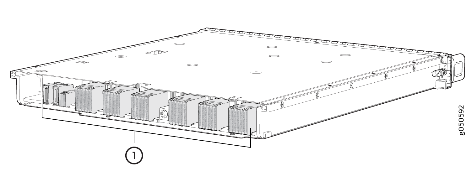 1—
1—Connectors
How to Store a Line Card
You must store line cards either in the chassis or in a spare shipping container, horizontally and sheet-metal side down. Don’t stack these units on top of one another or on top of any other component. Place each unit separately in an antistatic bag or on an antistatic mat placed on a flat, stable surface.
Because these units are heavy and because antistatic bags are fragile, inserting the line card into the bag is best done by two people.
To insert a line card into an antistatic bag:
- Hold the unit horizontally with the faceplate toward you.
- Slide the opening of the bag over the connector edge.
If you must insert the line card into a bag by yourself:
-
Lay the unit horizontally on an antistatic mat that is on a flat, stable surface with the sheet-metal side down.
-
Orient the unit with the faceplate toward you.
-
Carefully insert the connector edge into the opening of the bag and pull the bag toward you to cover the unit.
Take a PTX10004 Line Card Online or Offline
The offline/online (OFF) button is recessed below the faceplate directly below the status (STS) LED. You can take any of the PTX10004 line cards online or offline using either of these two methods:
-
Press the OFF button with a non-conductive pin tool, such as a toothpick, until the STS LED turns off after about 5 seconds.
-
Issue the CLI command:
user@host> request chassis pic fpc-slot fpc-slot pic-slot pic-slot offline
Install a PTX10004 Line Card
Before you install a line card in the router chassis:
-
Ensure that you have taken the necessary precautions to prevent electrostatic discharge (ESD) damage. See Prevention of Electrostatic Discharge Damage.
-
Ensure that you know how to handle and store the line card. See How to Handle and Store PTX10004 Line Cards.
-
Inspect the connector edge of the line card for physical damage. Installing a damaged line card might damage the router.
-
Ensure that the router has sufficient power to power the line card while maintaining its n+1 power redundancy. To determine whether the router has enough power available for the line card, use the
show chassis power-budget-statisticscommand. -
Ensure that you have the following parts and tools available to install a line card in the router:
-
ESD grounding strap
-
Phillips (+) screwdriver, number 2
-
To install a line card in the router chassis:
-
Wrap and fasten one end of the ESD grounding strap around your bare wrist
and connect the other end of the strap to one of the ESD points on the
chassis. An ESD point is located above the status LED panel on the front of
the router chassis. See Figure 2.
Figure 2: ESD Point on the Front of the PTX10004
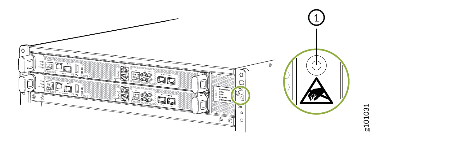 1—
1—ESD point
-
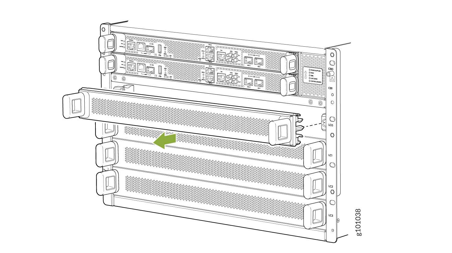
Remove the line card cover by grasping the handles and pulling straight out
to expose the slot for the line card. See Figure 3.
Figure 3: Remove the Cover for a Line Card
 CAUTION:
Do not lift the line card by holding the edge connectors or the handles on the faceplate. Neither the handles nor the edge connectors can support the weight of the line card. Lifting the line card by the handles or edge connectors might bend them, which would prevent the line cards from being properly seated in the chassis. See Figure 4.
Figure 4: Line-Card Connectors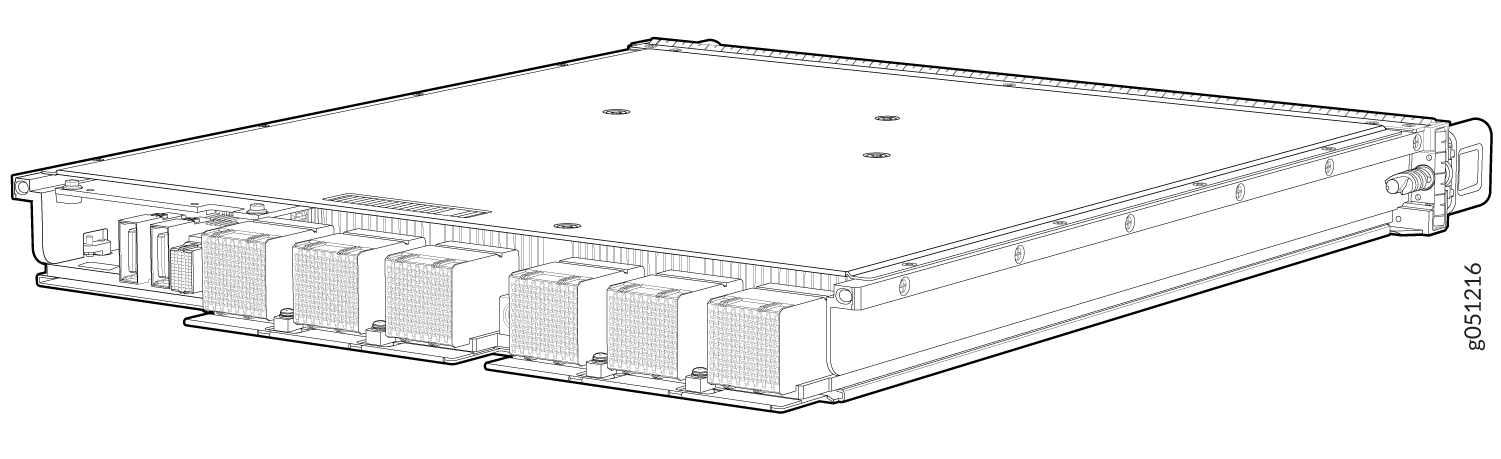
-
Gently slide the line card all the way into the slot until the handle holes
align. See Figure 5.
Figure 5: Insert the Line Card into the Slot and Rotate the Handles
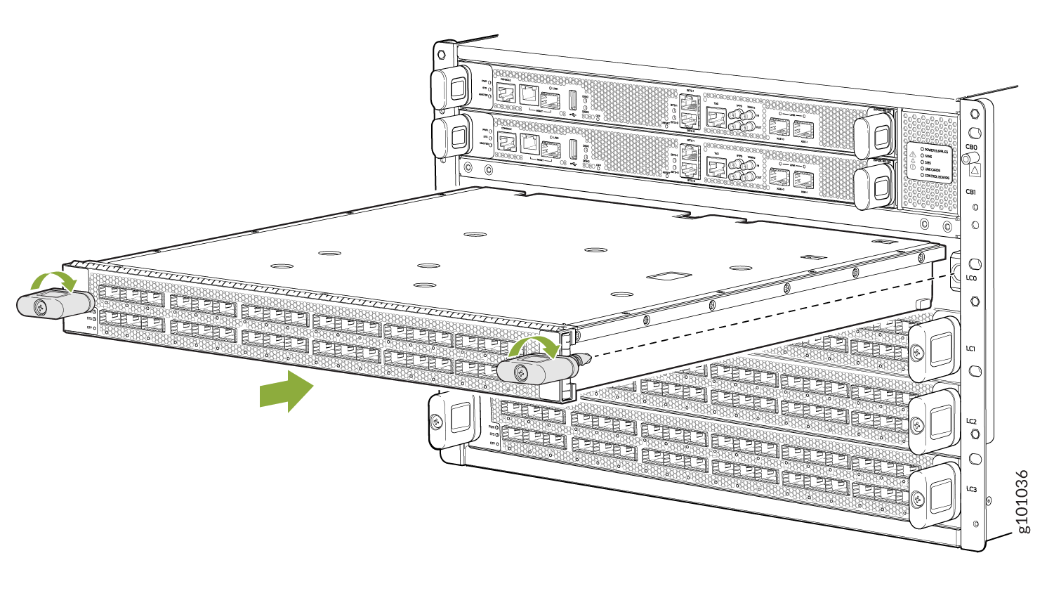
It takes approximately six minutes for the line card to be online. The status LED on the line card is lit steadily in green when the line card is online.
Fabric Link EvaluationIf your line card supports fabric link evaluation, wait for up to one minute after the line card comes online for the fabric link evaluation to start. The Status LED blips in green color when the fabric link evaluation is in progress. The line card continues to operate normally while the fabric link evaluation is in progress. Depending on the number of line cards installed in the chassis, it can take up to 17 minutes for the fabric link evaluation to complete.
After the fabric link evaluation is completed, if the fabric link quality is good and the line card is operating correctly, the status LED is lit steadily in green color. If the fabric link quality is sub-optimal, the status LED is lit steadily in amber color.
If the fabric link quality is sub-optimal:
If the fabric link quality is sub-optimal, it could be because the connectors on the line card might not have connected properly to the connectors on the SIB. You must remove the line card and install it again (see Remove a PTX10004 Line Card and Install a PTX10004 Line Card).
If the fabric link quality is sub-optimal after you install the line card the second time, you must remove the line card and install it one more time.
If the fabric link quality is sub-optimal after you install the line card the second time, contact customer support.
Remove a PTX10004 Line Card
If you have the optional line-card cable management system, it’s not necessary to remove the cable management system before removing the line card.
Before you remove a line card from the router chassis:
-
Ensure that you have taken the necessary precautions to prevent electrostatic discharge (ESD) damage. See Prevention of Electrostatic Discharge Damage.
-
If there are any optical cables (including transceivers installed in the line card), remove them before you remove the line card. See How to Disconnect a Fiber-Optic Cable from a Transceiver on a PTX10004 Router.
-
Ensure that you know how to handle and store the line card. See How to Handle and Store PTX10004 Line Cards.
-
Ensure that you have the following parts and tools available to remove a line card from a PTX10004 chassis:
-
ESD grounding strap
-
An antistatic bag or an antistatic mat
Note:Placing a line card in an electrostatic bag might require a second person to assist with sliding the line card into the bag.
-
Replacement line card or a cover for the empty slot
-
To remove a line card from a PTX10004 router chassis:
-
Wrap and fasten one end of the ESD grounding strap around your bare wrist
and connect the other end of the strap to one of the ESD points on the
chassis. An ESD point is located above the status LED panel on the front of
the router chassis. See Figure 6.
Figure 6: ESD Point on the Front of the PTX10004
1—
ESD point
-
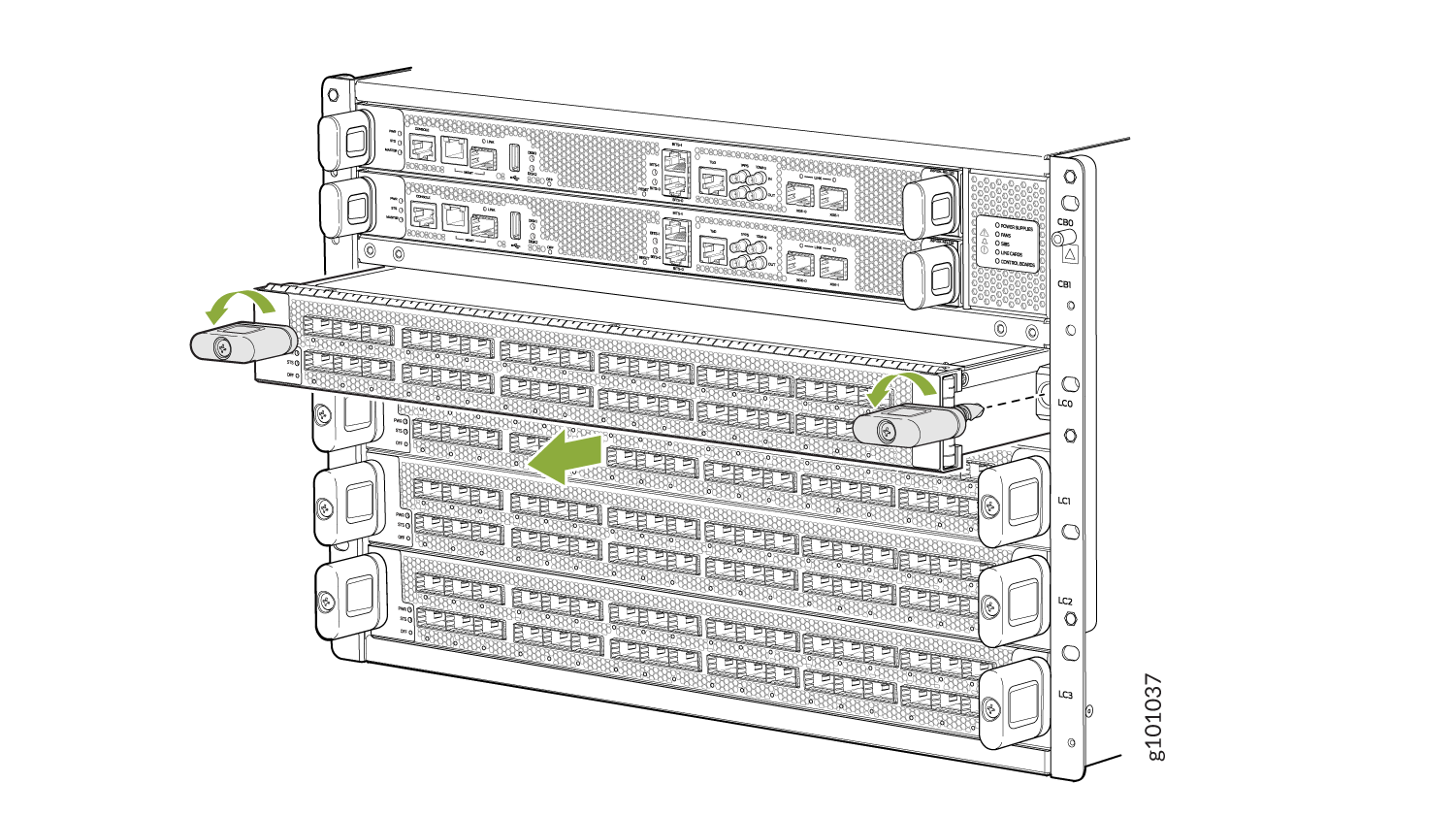
Unscrew the line card from the chassis by continually turning the handles
to the left until the line card is fully unseated. See Figure 7.
Figure 7: Remove a PTX10004 Line Card
-
Grasp both sides of the line card at midpoint and remove the line card from
the chassis. Either have someone assist you in putting the line card into
the antistatic bag or rest the card on the antistatic mat. Take care not to
bump or store the line cards on the connectors. See Figure 8.
Figure 8: Line Card Connectors
Install the PTX10004 Cable Management System
The PTX10004 cable management system is an optional, orderable kit (JLC-CBL-MGMT-KIT) that organizes and protects optical cabling attached to the line cards. After a line card is installed, you can still remove the line card without needing to remove the cable management system.
Ensure that you have the following parts and tools available to install the PTX10004 cable management system on a line card:
-
Phillips (+) screwdriver, number 2
To install the cable management system (see Figure 9):
-
Open the shipping carton for cable management system and check that you
have:
-
Two handle extensions
-
One cable tray
Figure 9: Cable Management System Components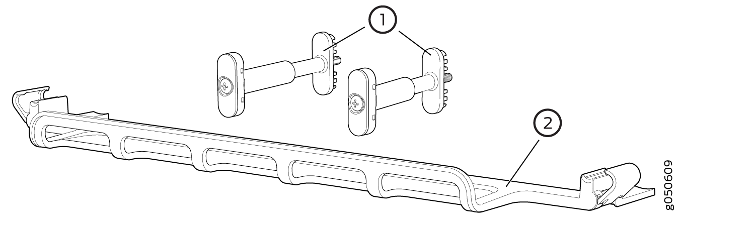 1—
1—Handle extensions
2—Cable tray
-
-
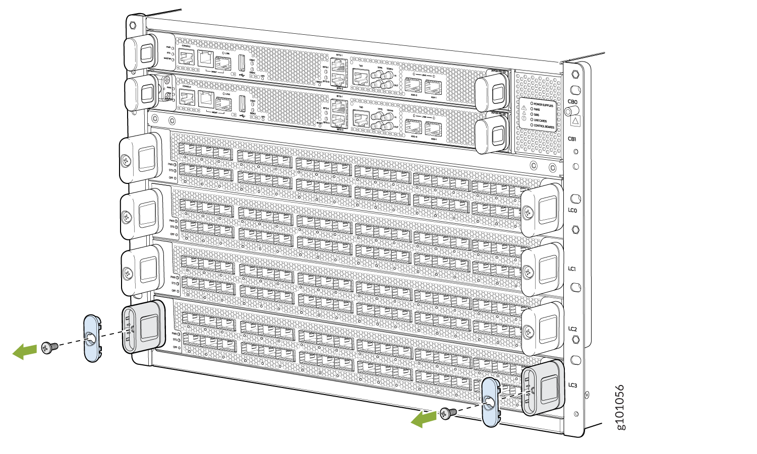
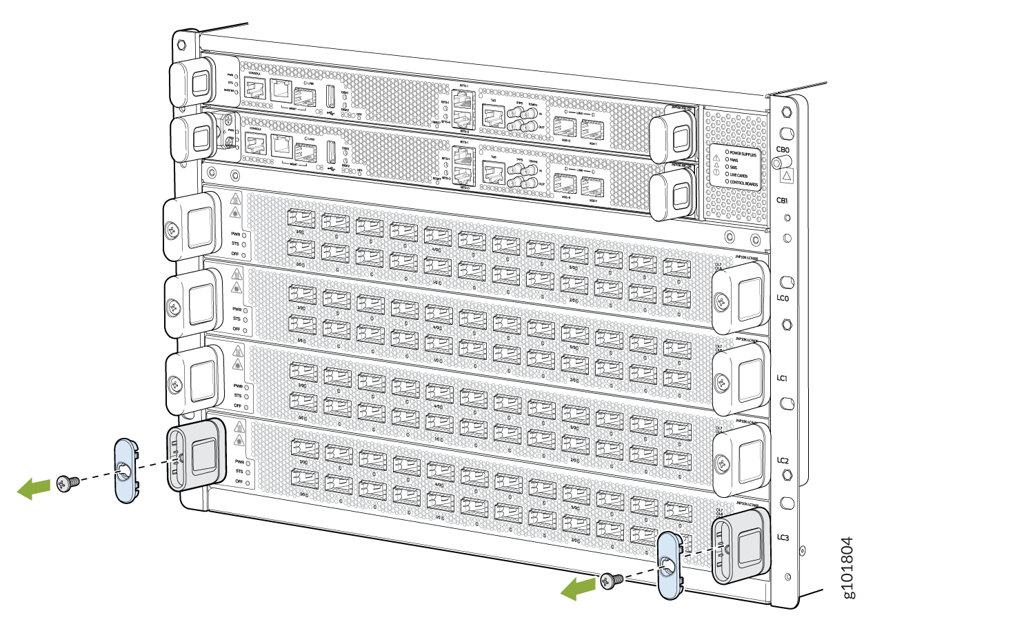
Use the Phillips screwdriver to loosen and remove the screws on the two
line-card handles (see Figure 10).
Figure 10: Remove the Handle Screws
-
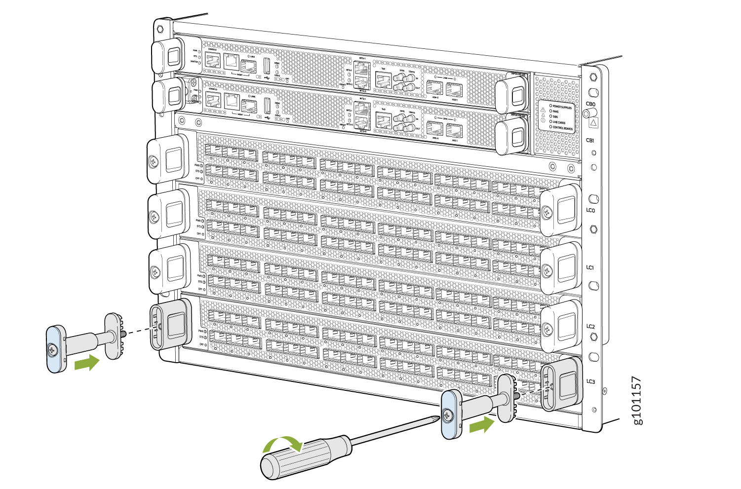
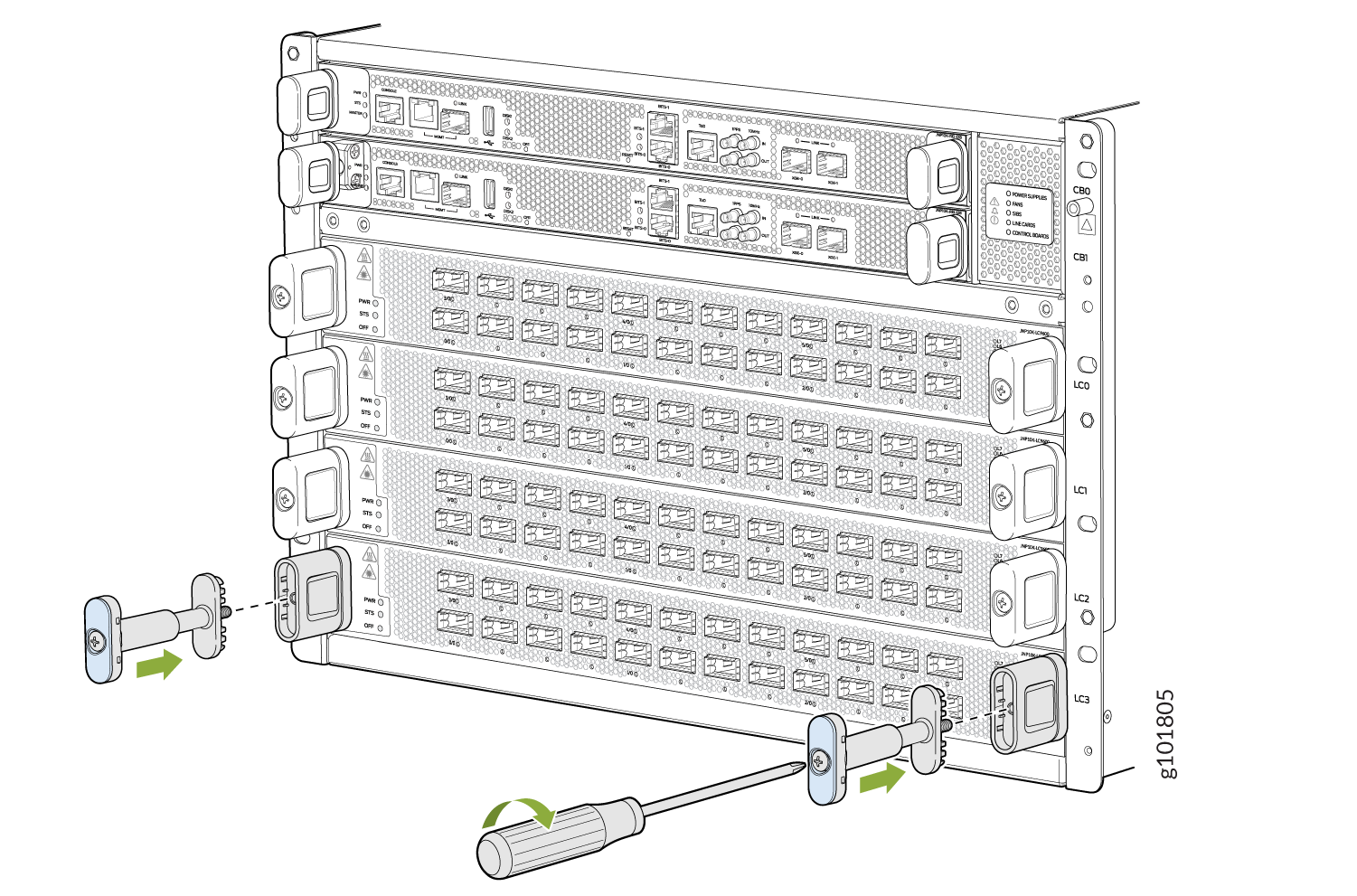
Replace the blue cap on the line-card handle with the two handle extensions
(see Figure 11).
Figure 11: Attach the Handle Extensions
-
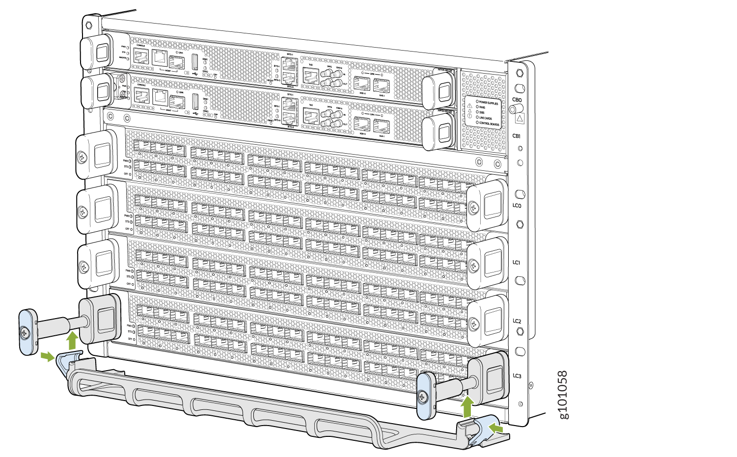
Snap to close the blue clips of the cable tray around the handle extensions
(see Figure 12).
Figure 12: Add the Cable Tray
-
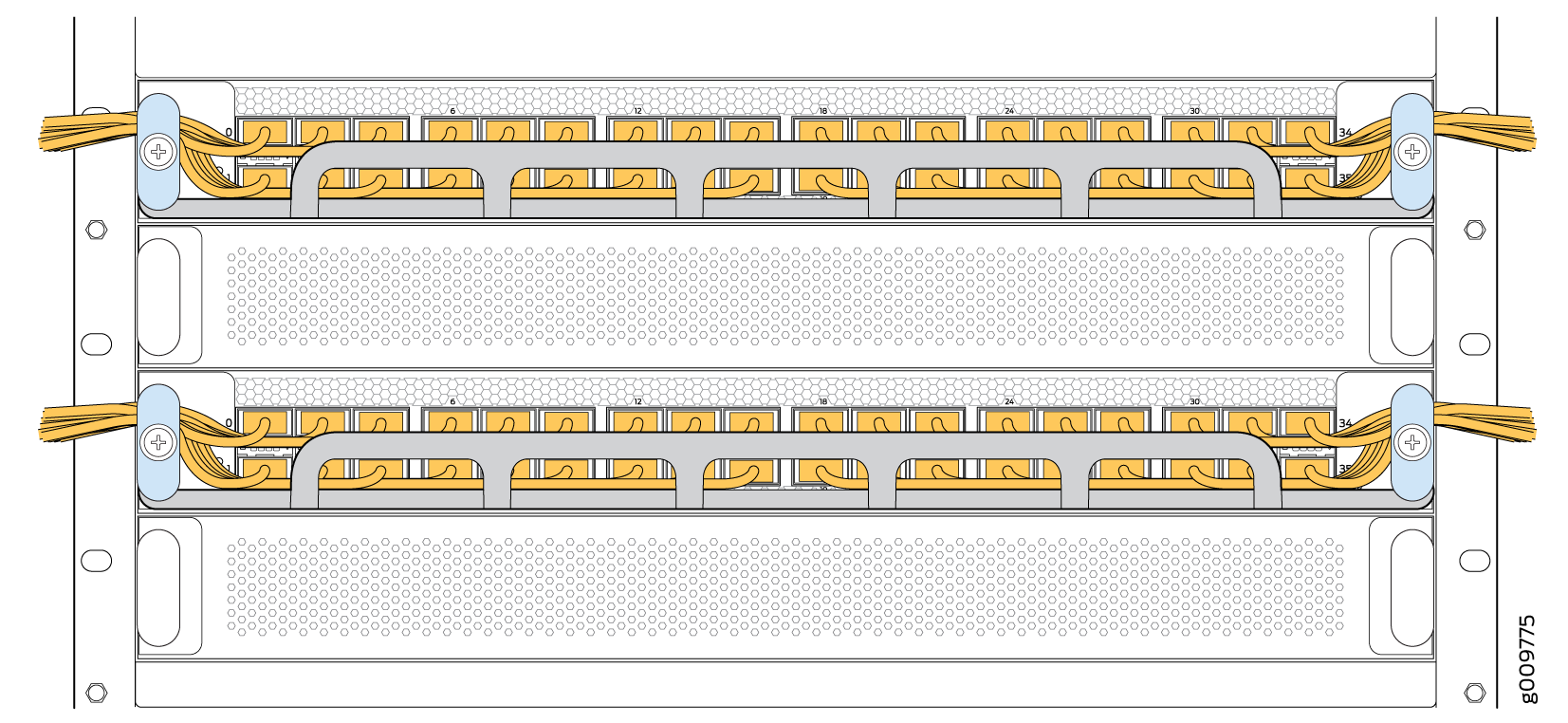
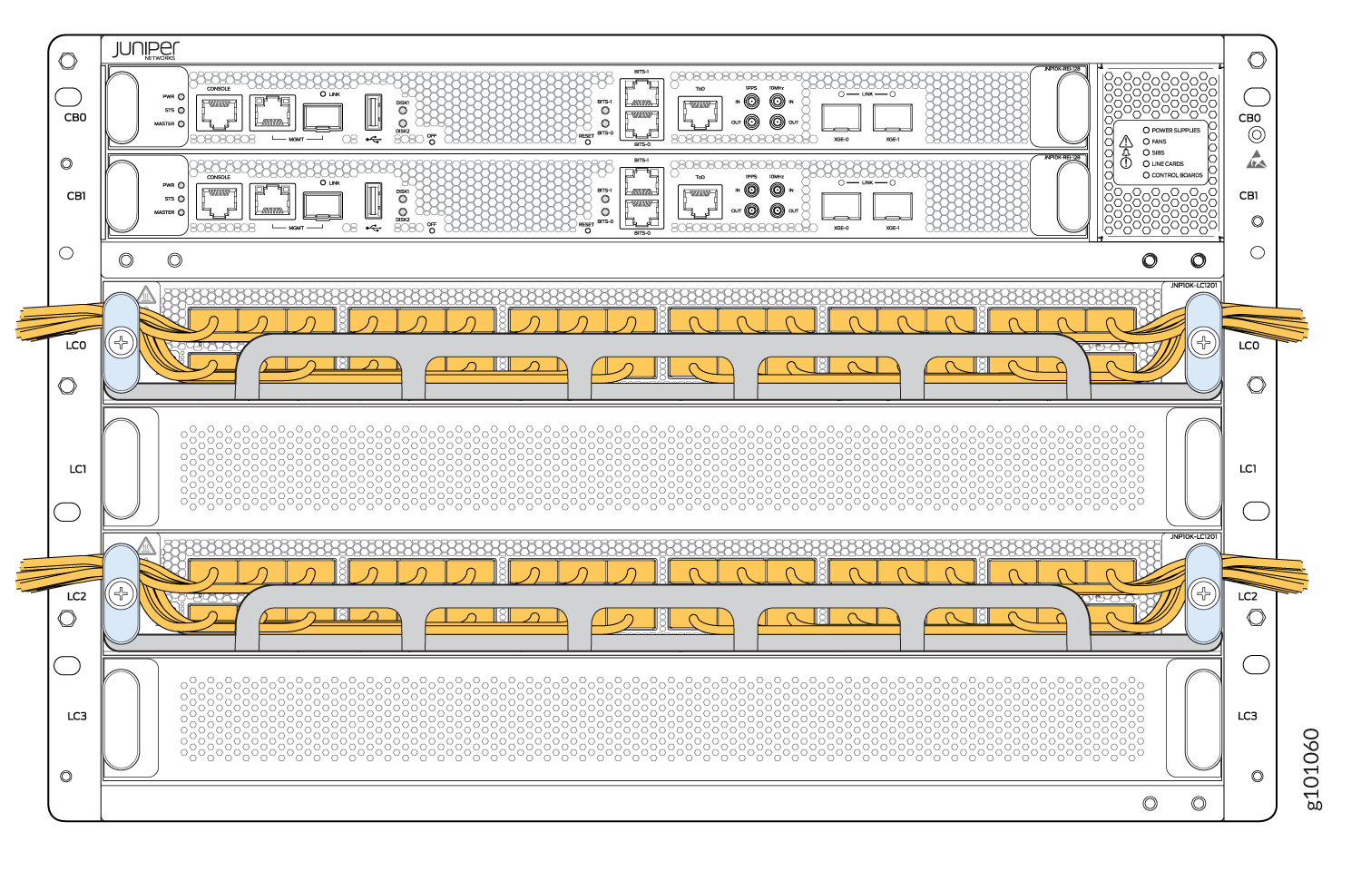
Drape and tie the optical cables to the side (see Figure 13). Another option is to drape some of the cables under the handle
extension and some cables over the handle extension.
Figure 13: Completed Cable Management System
Install the Cable Management System—JLC-CBL-MGMT-KIT
The Juniper Networks JLC-CBL-MGMT-KIT cable management system is an optional, orderable kit. This kit organizes and protects optical cabling attached to the line cards. After you install a line card, you can still remove the line card without needing to remove the cable management system.
Ensure that you have the following tool available to install the cable management system on a line card:
Phillips (+) screwdriver, number 2
To install the cable management system:
-
Open the shipping carton for the cable management system and check that you have:
-
Two handle extensions
-
One cable tray
Figure 14: Cable Management System Components 1—
1—Handle extensions
2—Cable tray
-
-
Use the Phillips screwdriver to loosen and remove the screws on the two line-card
handles.
Figure 15: Remove the Handle Screws
-
Replace the blue cap on the line-card handle with the two handle extensions.
Figure 16: Attach the Handle Extensions
-
Snap to close the blue clips of the cable tray around the handle extensions.
Figure 17: Add the Cable Tray
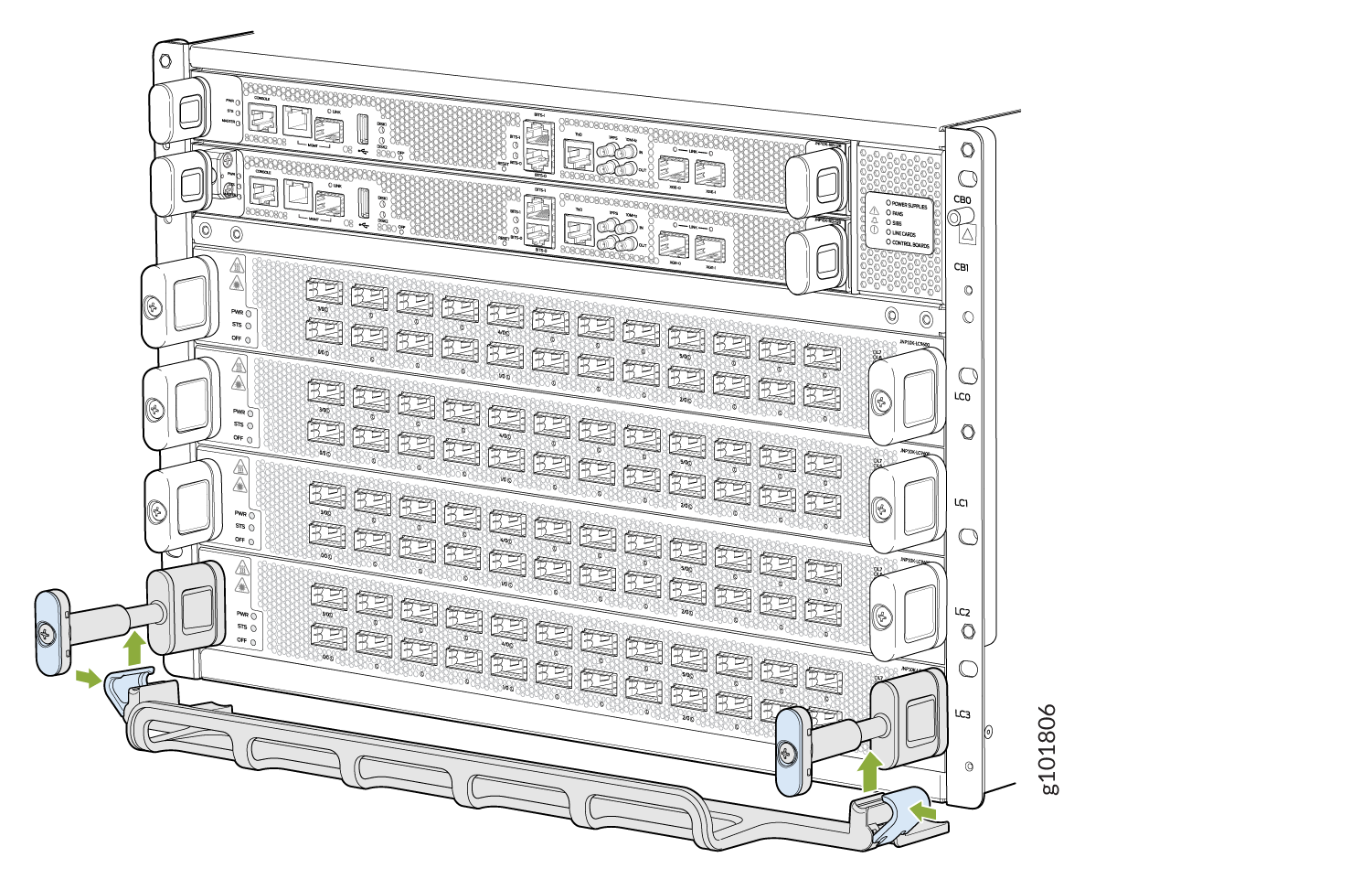 Figure 18: Completed Cable Management System
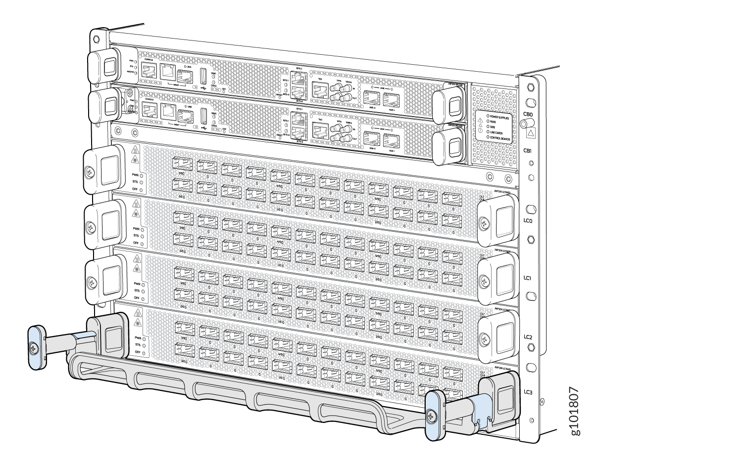
-
Drape and tie the optical cables to the side. Another option is to drape some of the
cables under the handle extension and some cables over the handle extension.