PTX10004 Line Card Components and Descriptions
The line cards in PTX10004 routers combine a Packet Forwarding Engine and Ethernet interfaces in a single assembly. Line cards are field-replaceable units (FRUs) that can be installed in the line-card slots on the front of the router chassis. The line cards are hot-insertable and hot-removable—you can remove and replace them without powering off the router or disrupting router functions.
PTX10K-LC1201-36CD Line Card
The PTX10K-LC1201-36CD (model number: JNP10K-LC1201) is a 36-port line card that provides a line rate throughput of 14.4 Tbps. The 36 QSFP56-DD ports support a speed of up to 400 Gbps (see Figure 1). You can channelize the ports to operate at 200-Gbps, 100-Gbps, 50-Gbps, 25-Gbps, or 10-Gbps speed by using breakout cables.
Overview
The line card houses five Juniper Networks' custom ASICs, and each ASIC houses two Packet Forwarding Engines. One packet forwarding engine in the fifth ASIC is not used.
You can install the PTX10K-LC1201-36CD line card in the PTX10004, PTX10008, and PTX10016 chassis horizontally at the front of the chassis.
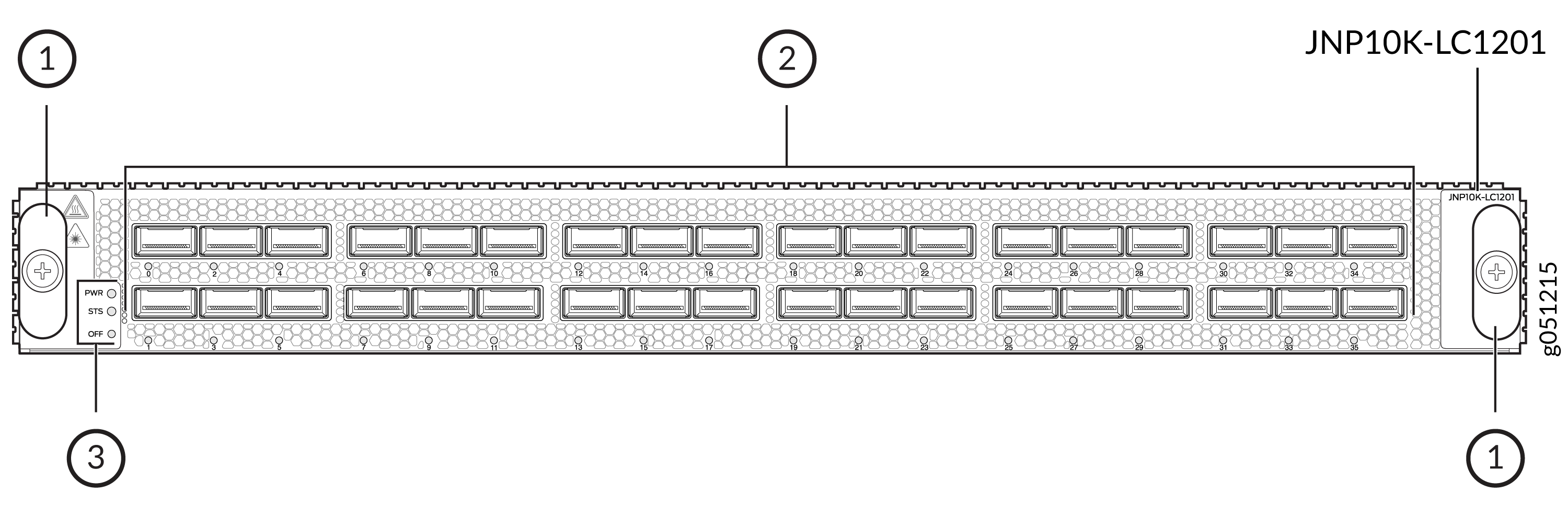
1 — Handles | 3 — Power LED (PWR), status LED (STS), and offline button (OFF) |
2 — Network ports and LEDs |
PTX10004 routers running Junos OS Evolved Release 20.3R1 with Junos Continuity and later support the PTX10K-LC1201-36CD line card. PTX10008 routers running Junos OS Evolved Release 19.4R1-S1 and later support the PTX10K-LC1201-36CD line card. PTX10016 routers running Junos OS Evolved Release 21.2R2 and later support the PTX10K-LC1201-36CD line card. The PTX10K-LC1201-36CD line card interoperates with the PTX10K-LC1202-36MR line card on a PTX10004, PTX10008, or PTX10016 router. The PTX10K-LC1201-36CD line card interoperates with the PTX10K-LC1301-36DD line card in PTX10004 and PTX10008 routers.
|
Component (Field Replaceable Unit) |
Part Number for the PTX10004 |
Part Number for the PTX10008 |
Part Number for the PTX10016 |
|---|---|---|---|
|
Switch fabric: Switch Interface Board (SIB) |
JNP10004-SF3 |
JNP10008-SF3 or JNP10008-SF5 The support for JNP10008-SF5 is available from Junos OS Evolved Release 24.4R2. |
JNP10016-SF3 |
|
Routing and Control Board (RCB) |
JNP10K-RE3-E, JNP10K-RE3-E-LT, JNP10K-RE2-E128, JNP10K-RE1-E128, JNP10K-RE1-ELT, or JNP10K-RE1-E |
JNP10K-RE3-E, JNP10K-RE3-E-LT, JNP10K-RE2-E128, JNP10K-RE1-E128, JNP10K-RE1-ELT, or JNP10K-RE1-E |
JNP10K-RE3-E, JNP10K-RE3-E-LT, JNP10K-RE2-E128, JNP10K-RE1-E128, JNP10K-RE1-ELT, or JNP10K-RE1-E |
|
Fan tray |
JNP10004-FAN2, JNP10004-FAN3 |
JNP10008-FAN2, JNP10008-FAN3 |
JNP10016-FAN2 |
|
Fan tray controller |
JNP10004-FTC2, JNP10004-FTC3 |
JNP10008-FTC2, JNP10004-FTC3 |
JNP10016-FTC2 |
|
Power supply |
JNP10K-PWR-AC2, JNP10K-PWR-AC3, JNP10K-PWR-DC2, JNP10K-PWR-DC3, JNP10K-PWR-AC3H |
JNP10K-PWR-AC2, JNP10K-PWR-AC3, JNP10K-PWR-DC2, JNP10K-PWR-DC3, JNP10K-PWR-AC3H |
JNP10K-PWR-AC2 JNP10K-PWR-AC3, JNP10K-PWR-DC2, JNP10K-PWR-DC3, JNP10K-PWR-AC3H |
Network Ports
The QSFP56-DD ports support:
-
400GbE transceivers (QSFP56-DD)
-
400GbE active optic cables (QSFP56-DD AOCs)
-
4 x 100GbE transceivers (QSFP56-DD)
-
2 x 100GbE transceivers (QSFP28-DD)
-
100GbE transceivers (QSFP28)
-
100GbE AOCs (QSFP28)
-
40GbE transceivers (QSFP+)
-
40GbE to 10GbE QSA (Junos OS Release 20.2R1 and later)
Channelization
All 36 ports of the PTX10K-LC1201-36CD line card default to 400GbE. You can either set all the ports to a specific speed and channelization or channelize each port individually. The CLI syntax to channelize a port on the PTX10K-LC1201-36CD is release dependent.
For software releases from Junos OS Evolved Release 19.4R1-S1 to Junos OS Evolved Release 20.1R2:
Use the pic-mode and speed options in the Junos OS Evolved
operational mode set chassis command:
user@host> set chassis fpc slot slot-number pic 0 pic-mode speed 400g|200g|100g|50g|40g|25g|10g
In this example, fpc slot represents the line card slots. There is a single
PIC in the PTX10K-LC1201-36CD; it is always numbered zero. The pic-mode option
indicates that you are configuring all of ports on the PIC and not an individual port. With the
speed options, you can configure 100-Gbps or 40-Gbps speed on all 36 ports, or
you can configure four 10-Gbps channels on each of the 36 ports.
For example, to set 100-Gbps speed on all ports in slot 2:
user@host> set chassis fpc 2 pic 0 pic-mode speed 100g
To individually configure a port, you need to specify both the speed and number of subports (channels).
user@host> set chassis fpc fpc-number pic 0 port port-number speed 400g|200g|100g|50g|40g|25g|10g number-of-subports subport-number
For example, to channelize port 15 in slot 0 to 4 downstream 100GbE interfaces:
user@host> set chassis fpc 0 pic 0 port 15 speed 100g number-of-subports 4
The resulting interfaces would be:
et-0/0/15:0
et-0/0/15:1
et-0/0/15:2
et-0/0/15:3
If you do not specify the number-of-subports value when configuring an
individual port, the system defaults to a value of 1. The same example, without the
number-of-subports option, would then result in one downstream 100GbE
interface.
For software releases Junos OS Evolved Release 20.1R2 and later, the speed
and number-of-subports options are in the interfaces
hierarchy. For example, to channelize port 15 in slot 0 to four downstream 100GbE
interfaces:
[edit-interfaces]
user@host> et-0/0/15
 {speed 100g;
number-of-subports 4;
}
et-0/0/15:0 {unit 0}
et-0/0/15:1 {unit 0}
et-0/0/15:2 {unit 0}
et-0/0/15:3 {unit 0}
After you save and commit the changes, each of the following resulting interfaces would be:
et-0/0/15:0
et-0/0/15:1
et-0/0/15:2
et-0/0/15:3
Bandwidth Support
Table 2 lists the bandwidth supported by each PTX10K-LC1201-36CD line card.
|
Number of SIBs Used |
Bandwidth per Slot Without Fabric Redundancy |
|---|---|
|
6 |
14.4 Tbps |
|
5 |
12 Tbps |
|
4 |
9.6 Tbps |
|
3 |
7.2 Tbps |
Network LEDs
Each network port has a single tricolored LED that indicates link activity and status. The red, amber, and green colors on the LED have different interpretations depending on whether the port is channelized or not channelized, and whether the beacon is activated. If the beacon feature is activated on the port, the port blinks.
|
Port Status |
Normal State |
Description |
|---|---|---|
|
Nonchannelized |
Unlit, off |
A transceiver is not installed or the link is down because of a loss of signal. |
|
Green, on steadily |
A link is established. |
|
|
Amber, on steadily |
The link is down because of a remote error or because the port was disabled through the CLI. |
|
|
Red, on steadily |
The link is down because of a hardware failure or a local error. |
|
|
Channelized |
Unlit, off |
All channels are down because of loss of signal. |
|
Green, on steadily |
A link is established and all channels are up. |
|
|
Amber, on steadily |
Applies to all other cases. |
|
|
Red, on steadily |
The port has a hardware failure. |
Line Card Status LEDs
The line card has a power LED (PWR) and a status LED (STS).
|
LED |
State |
LED Indication |
Beacon/Port Location On |
|---|---|---|---|
|
Power (PWR) |
The line card has no power. |
Off |
Off |
|
The line card has power and is operating correctly. |
Green, on steadily |
Green, on steadily |
|
|
The line card has a fault condition. |
Red, on steadily |
Red, on steadily |
|
|
Status (STS) |
The line card is disabled or offline. |
Off |
Off |
|
The line card is online and operating correctly. |
Green, on steadily |
Green, blinking |
|
|
The line card is booting. |
Green, blinking |
Green, blinking |
|
|
The line card has a fault condition. |
Red, on steadily |
Red, blinking |
PTX10K-LC1202-36MR Line Card
- Overview
- Components Required for PTX10K-LC1202-36MR
- Network Ports and Channelization
- Bandwidth Support
- Network LEDs
- Line Card Status LEDs
Overview
The PTX10K-LC1202-36MR (model number: JNP10K-LC1202) is a 36-port line card that provides a line rate throughput of 4.8 Tbps. The line card has 32 QSFP28 ports, each capable of supporting a maximum speed of 100 Gbps, and four QSFP56-DD ports, each capable of supporting a maximum speed of 400 Gbps (see Figure 2).
In a pure 100-Gbps port speed configuration, the line card supports a throughput of 3.6 Tbps (each of the 36 ports runs at 100-Gbps speed).
In a mixed-speed configuration of 100 Gbps and 400 Gbps, the line card supports a line rate throughput of 4.8 Tbps (thirty-two 100-Gbps ports and four 400-Gbps ports).
The line card houses two Juniper Networks' custom ASICs, and each ASIC houses two Packet Forwarding Engines. The line card supports a maximum throughput of 1.2 Tbps per Packet Forwarding Engine.
You can install the PTX10K-LC1202-36MR line card in the PTX10004, PTX10008, and PTX10016 chassis horizontally at the front of the chassis.
The acoustics noise for the line card is 85 dBA.
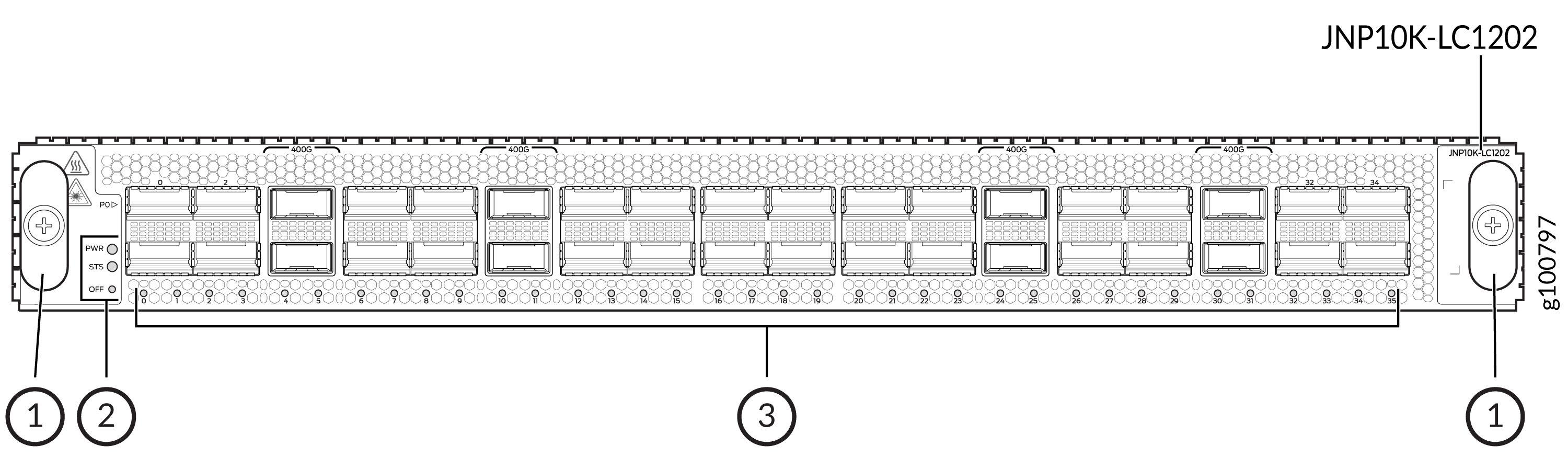
1 — Handles | 3 — Network ports and LEDs |
2 — Power LED (PWR), status LED (STS), and offline button (OFF) |
Components Required for PTX10K-LC1202-36MR
PTX10004 routers running Junos OS Evolved Release 20.3R1 with Junos Continuity and later support the PTX10K-LC1202-36MR line card. PTX10008 routers running Junos OS Evolved Release 20.3R1 and later (with Junos Continuity) support the PTX10K-LC1202-36MR line card. PTX10016 routers running Junos OS Evolved Release 21.2R2 and later support the PTX10K-LC1202-36MR line card. The PTX10K-LC1202-36MR line card interoperates with the PTX10K-LC1201-36CD line card on a PTX10004, PTX10008, or PTX10016 router. The PTX10K-LC1202-36MR line card interoperates with the PTX10K-LC1301-36DD line card in PTX10004 and PTX10008 routers.
|
Component (FRU) |
Part Number for the PTX10004 |
Part Number for the PTX10008 |
Part Number for the PTX10016 |
|---|---|---|---|
|
Switch fabric: Switch Interface Board (SIB) |
JNP10004-SF3 |
JNP10008-SF3 or JNP10008-SF5 The support for JNP10008-SF5 is available from Junos OS Evolved Release 24.4R2. |
JNP10016-SF3 |
|
Routing and Control Board (RCB) |
JNP10K-RE3-E, JNP10K-RE3-E-LT, JNP10K-RE2-E128, JNP10K-RE1-E128, JNP10K-RE1-ELT, or JNP10K-RE1-E |
JNP10K-RE3-E, JNP10K-RE3-E-LT, JNP10K-RE2-E128, JNP10K-RE1-E128, JNP10K-RE1-ELT, or JNP10K-RE1-E |
JNP10K-RE3-E, JNP10K-RE3-E-LT, JNP10K-RE2-E128, JNP10K-RE1-E128, JNP10K-RE1-ELT, or JNP10K-RE1-E |
|
Fan tray |
JNP10004-FAN2, JNP10004-FAN3 |
JNP10008-FAN2, JNP10008-FAN3 |
JNP10016-FAN2 |
|
Fan tray controller |
JNP10004-FTC2, JNP10004-FTC3 |
JNP10008-FTC2, JNP10008-FTC3 |
JNP10016-FTC2 |
|
Power supply |
JNP10K-PWR-AC2, JNP10K-PWR-AC3, JNP10K-PWR-DC2, JNP10K-PWR-DC3, or JNP10K-PWR-AC3H |
JNP10K-PWR-AC2, JNP10K-PWR-AC3, JNP10K-PWR-DC2, JNP10K-PWR-DC3, or JNP10K-PWR-AC3H |
JNP10K-PWR-AC2 or JNP10K-PWR-DC2, JNP10K-PWR-DC3, or JNP10K-PWR-AC3H |
Network Ports and Channelization
On the PTX10K-LC1202-36MR line card, the ports 4, 10, 24, and 30 are 400GbE (QSFP56-DD) ports, whereas the rest are 100GbE (QSFP28) ports.
Figure 3 shows the 400GbE ports highlighted.
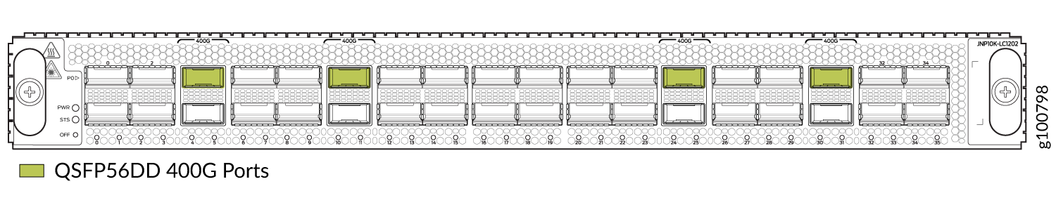
By using breakout cables, you can channelize the PTX10K-LC1202-36MR ports.
The QSFP56-DD ports (ports 4, 10, 24, and 30) on the line card support the following transceivers:
-
1x400GbE transceivers (QSFP56-DD)
-
4x100GbE transceivers (QSFP56-DD)
-
2x100GbE transceivers (QSFP28-DD)
-
1x100GbE transceivers (QSFP28)
-
2x50GbE transceivers (QSFP28)
-
1x40GbE transceivers (QSFP+)
-
8x25GbE transceivers (QSFP28-DD)
-
4x25GbE transceivers (QSFP28)
-
4x10GbE transceivers (QSFP+)
-
1x10GbE transceivers (SFP+)
-
40GbE to 10GbE QSA, starting in Junos OS Evolved Release 20.4R1 and later.
The QSFP28 ports 0, 2, 5 through 9, 11 through 18, 20, 22, 23, 25 through 29, and 31 through 35 on the line card support the following transceivers:
-
1x100GbE transceivers (QSFP28)
-
2x50GbE transceivers (QSFP+)
-
1x40GbE transceivers (QSFP+)
-
4x25GbE transceivers (QSFP28)
-
4x10GbE transceivers (QSFP+)
-
1x10GbE transceivers (QSFP+)
The QSFP28 ports 1, 3, 19, and 21 on the line card support the the 1x100GbE QSFP28 transceivers.
The ports 1, 3, 19, and 21 must be configured as unused if the preceding ports (0, 2, 18, and 20) are not in 100-Gbps mode. This means, of the 36 ports on the PTX10K-LC1202-36MR line card, only 32 ports are available to be configured as 4x25GbE and 4x10GbE ports.
See the Port Checker tool to see the supported port speeds.
You can configure port speeds at the interface level using the set interfaces <interface-name> speed <speed> command.
Bandwidth Support
Table 6 explains the bandwidth supported by each PTX10K-LC1202-36MR line card.
|
Number of SIBs Used |
Bandwidth per Slot Without Fabric Redundancy |
|---|---|
|
6 |
4.8 Tbps |
|
5 |
4 Tbps |
|
4 |
3.2 Tbps |
|
3 |
2.4 Tbps |
Network LEDs
Each network port has a single tricolored LED that indicates link activity and status. The red, amber, and green colors on the LED have different interpretations depending on whether the port is channelized or not channelized, and whether the beacon is activated. If the beacon feature is activated on the port, the port blinks.
|
Port Status |
State |
Description |
|---|---|---|
|
Nonchannelized |
Unlit, off |
A transceiver is not present in the port, or the link is down because of a loss of signal. |
|
Green, on steadily |
A link is established. |
|
|
Amber, on steadily |
The link is down because of a remote error or because the port was disabled through the CLI. |
|
|
Red, on steadily |
The link is down because of a hardware failure or a local error. |
|
|
Channelized |
Unlit, off |
All channels are down because of loss of signal. |
|
Green, on steadily |
A link is established and all channels are up. |
|
|
Amber, on steadily |
Applies to all other cases. |
|
|
Red, on steadily |
The port has a hardware failure. |
Line Card Status LEDs
The line card has a power LED (PWR) and a status LED (STS).
|
LED |
State |
LED Indication |
Beacon/Port Location On |
|---|---|---|---|
|
Power (PWR) |
The line card has no power. |
Off |
Off |
|
The line card has power and is operating correctly. |
Green, on steadily |
Green, on steadily |
|
|
The line card has a fault condition. |
Red, on steadily |
Red, on steadily |
|
|
Status (STS) |
The line card is disabled or offline. |
Off |
Off |
|
The line card is online and operating correctly. |
Green, on steadily |
Green, blinking |
|
|
The line card is booting. |
Green, blinking |
Green, blinking |
|
|
The line card has a fault condition. |
Red, on steadily |
Red, blinking |
PTX10K-LC1301-36DD Line Card
- Overview
- Boot Time
- Components Required
- Bandwidth Support
- Network Port Status LEDs
- Line Card Status LEDs
Overview
The PTX10K-LC1301-36DD line card (model number: JNP10K-LC1301) is a 36-port line card that offers a line rate throughput of 28.8 Tbps. The 36 high-density 800-Gigabit Ethernet (800GbE) QSFP-DD ports support speeds of up to 800 Gbps. The line card houses two Juniper Networks' custom Express 5 ASICs, and each ASIC comprises of two Packet Forwarding Engines.
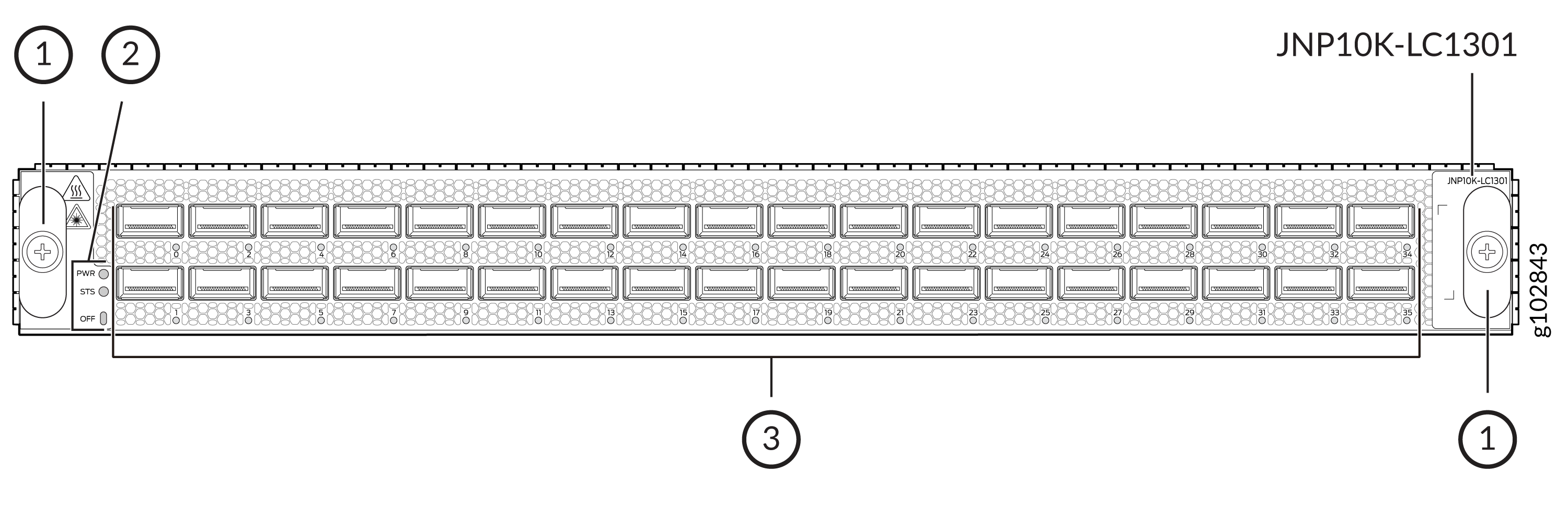
1 — Handles | 3 — Network ports and LEDs |
2 — Power LED (PWR), status LED (STS), and offline button (OFF) |
The ports support QSFP+, QSFP28, QSFP56-DD, and 400G-ZR transceivers. When the line card is operating in the normal power mode, you can install up to 36 800-Gbps or 2x400 Gbps transceivers.
You can also use breakout cables, active optical cables (AOCs), and the number-of-sub-ports (interface) configuration to channelize the ports to operate at the following speeds:
-
1x800 Gbps
-
2x400 Gbps
-
1x400 Gbps
-
8x100 Gbps
-
7x100 Gbps
-
6x100 Gbps
-
5x100 Gbps
-
4x100 Gbps
-
3x100 Gbps
-
2x100 Gbps
-
1x100 Gbps
-
8x50 Gbps
-
4x50 Gbps
-
2x50 Gbps
-
1x40 Gbps
-
8x25 Gbps
-
4x25 Gbps
-
4x10 Gbps
-
1x10 Gbps
The line card supports fabric link evaluation.
The links on the ports come up at 800-Gbps speed by default. You can change the port speed by using the set interfaces <interface-name> speed <speed> command.
Juniper Networks Port Checker (https://apps.juniper.net/port-checker/) provides a visual representation of various Juniper network devices, and assists to configure and validate different port combinations.
The software features for the line card are documented in Release Notes: Junos OS Evolved Release 24.4R1.
Boot Time
The boot time for the line card is approximately 566 seconds.
Components Required
|
Component |
Part Number for the PTX10008 |
Part Number for the PTX10004 |
|---|---|---|
|
Switch Interface Board (SIB) |
JNP10008-SF5 or JNP10008-SF3 Support for JNP10008-SF3 is available from Junos OS Evolved Release 25.4R1-S1. |
JNP10004-SF3 Support for JNP10004-SF3 is available from Junos OS Evolved Release 25.4R1-S1. |
|
Routing and Control Board (RCB) |
JNP10K-RE2-E128, JNP10K-RE1-E128, JNP10K-RE1-ELT, JNP10K-RE1-E, JNP10K-RE3-E, or JNP10K-RE3-E-LT |
JNP10K-RE2-E128, JNP10K-RE1-E128, JNP10K-RE1-ELT, JNP10K-RE1-E, JNP10K-RE3-E, or JNP10K-RE3-E-LT |
|
Fan tray |
JNP10008-FAN3 |
JNP10004-FAN3 |
|
Fan tray controller |
JNP10008-FTC3 |
JNP10004-FTC3 |
|
Power supply |
JNP10K-PWR-AC3, JNP10K-PWR-DC3, or JNP10K-PWR-AC3H |
JNP10K-PWR-AC3, JNP10K-PWR-DC3, or JNP10K-PWR-AC3H |
Bandwidth Support
|
Number of JNP10008-SF5 SIBs Used |
Bandwidth per Slot |
|---|---|
|
6 |
28.8 Tbps |
|
5 |
24 Tbps |
|
4 |
19.2 Tbps |
|
3 |
14.4 Tbps |
|
Number of JNP10004-SF3 or JNP10008-SF3 SIBs Used |
Bandwidth per Slot |
|---|---|
|
6 |
12.8 Tbps |
|
5 |
10.7 Tbps |
|
4 |
8.6 Tbps |
|
3 |
6.4 Tbps |
The maximum throughput that the line card offers in PTX10004 routers with JNP10004-SF3 installed and in PTX10008 routers with JNP10008-SF3 installed is 12.8 Tbps. The total throughput that a port group of nine ports (0 through 8, 9 through 17, 18 through 26, and 27 through 35) can offer is 3.2 Tbps. If a port group is oversubscribed, traffic is dropped at ingress, overriding the Class of Service (CoS) profiles.
Network Port Status LEDs
Each network port has a single tricolored LED that indicates link activity and status. The red, amber, and green colors on the LED have different interpretations depending on whether the port is channelized or not channelized, and whether the beacon is activated. If the beacon feature is activated on the port, the port blinks.
|
Port Status |
Description |
Color and State |
Beacon/Port Location On |
|---|---|---|---|
|
Not channelized |
A link is established. |
Green, on steadily |
Green, blinking |
|
The link is down because of a remote error or because the port was disabled through the CLI. |
Amber, on steadily |
Amber, blinking |
|
|
The link is down because of a hardware failure or a local error. |
Red, on steadily |
Red, blinking |
|
|
The port doesn't have a transceiver installed or the link is down because of a loss of signal. |
Unlit, off |
Green, blinking |
|
|
Channelized |
A link is established and all the channels are up. |
Green, on steadily |
Green, blinking |
|
All the other scenarios. |
Amber, on steadily |
Amber, blinking |
|
|
The port has a hardware failure or a fault. |
Red, on steadily |
Red, blinking |
|
|
All channels are down because of loss of signal. |
Unlit, off |
Green, blinking |
Line Card Status LEDs
The line card has a power LED (PWR) and a status LED (STS).
|
LED |
Description |
LED Color and State |
Beacon/Port Location On |
|---|---|---|---|
|
Power (PWR) |
The line card has power and is operating correctly. |
Green, on steadily |
Green, on steadily |
|
The line card has a fault condition. |
Red, on steadily |
Red, on steadily |
|
|
The line card has no power. |
Off |
Off |
|
|
Status (STS) |
The line card is online and operating correctly. |
Green, on steadily |
Green, blinking |
|
The line card is booting. |
Green, blinking |
Green, blinking |
|
|
Line card fabric link evaluation is in progress. |
Green, blipping |
Green, blinking |
|
|
The line card has improper fabric connectivity. |
Amber, on steadily |
Amber, blinking |
|
|
The line card has a fault condition. |
Red, on steadily |
Red, blinking |
|
|
The line card is disabled or offline. |
Off |
Off |
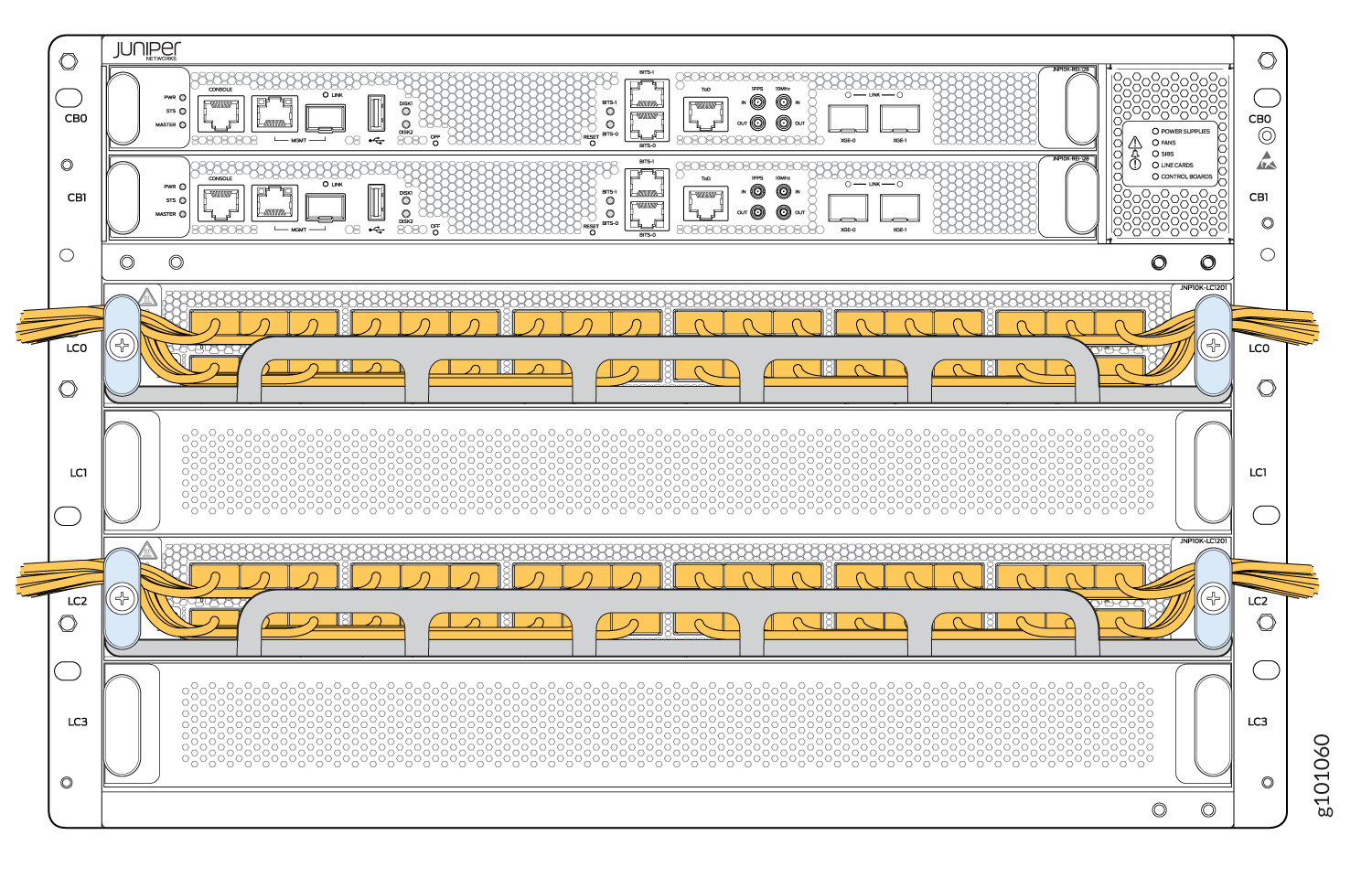
PTX10004 Cable Management System
You can use the PTX10004 cable management system (see Figure 5) to route optical cables away from the line-card ports for better airflow through the chassis. Using this optional system also makes it easier to use cable ties or strips to organize the cabling.
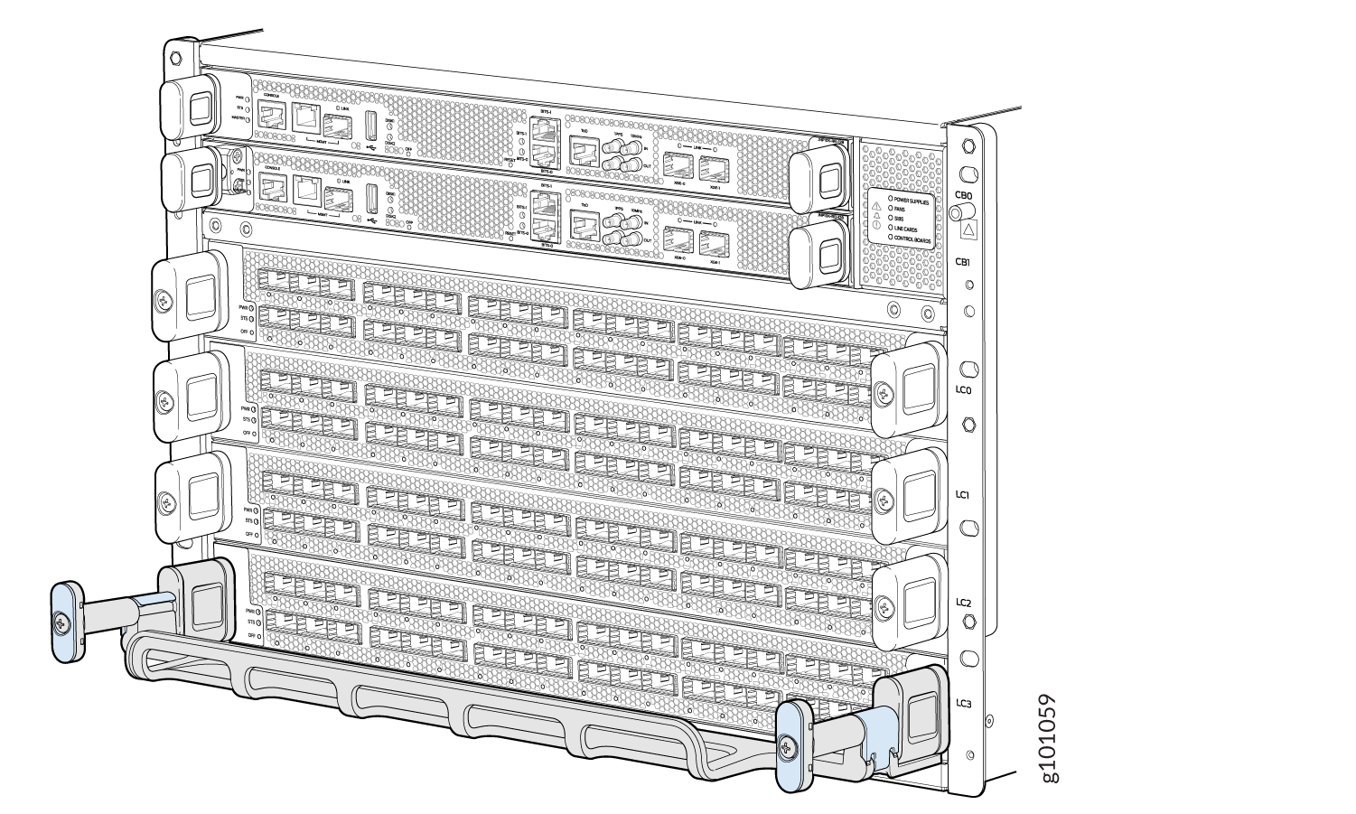
The cable management system comprises a set of handle extensions and a tray that snaps to the extensions (see Figure 6) for an individual line card. You can use the handle extensions with or without the cable tray. You don’t need to remove the handle extensions if you want to remove a line card.
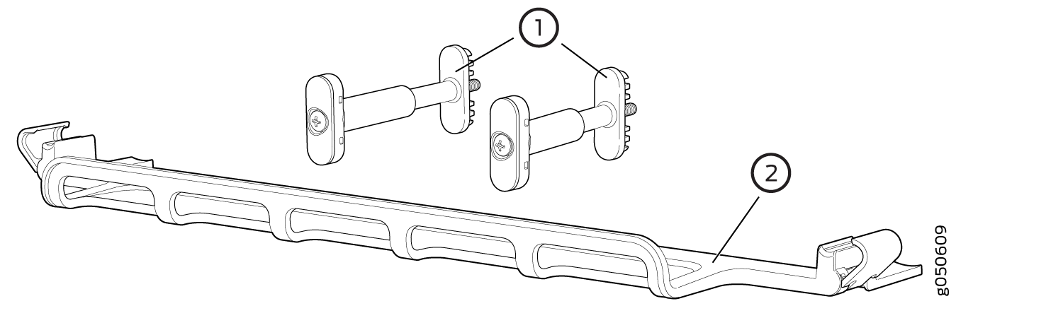
1 — Handle extensions | 2 — Cable tray |
Cables are draped across or under the handle extensions and then secured with cable wraps (see Figure 7).