PTX10004 Cooling System
The PTX10004 cooling system components work together to keep all components within the acceptable temperature range. If the maximum temperature specification is exceeded and the system cannot be adequately cooled, the Routing and Control Board (RCB) shuts down some or all of the hardware components.
PTX10004 Cooling System and Airflow
The cooling system in a PTX10004 chassis consists of dual fan trays (JNP10004-FAN2 or JNP10004-FAN3) with matching dual fan tray controllers (JNP10004-FTC2 or JNP10004-FTC3). Each fan tray requires a companion fan tray controller to be installed and operational to be hot-insertable and hot-removable.
Fan Tray
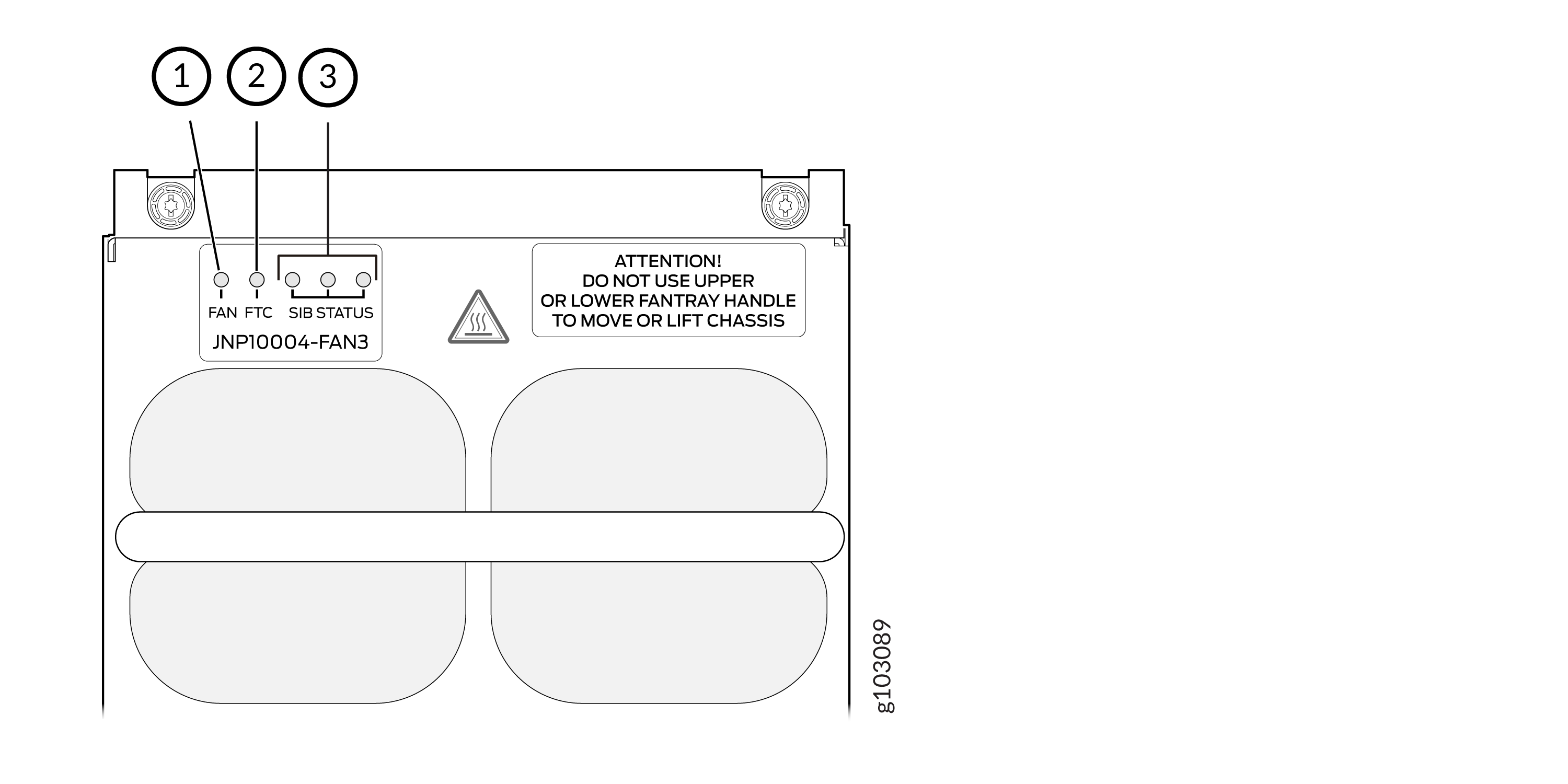
The JNP10004-FAN3 fan tray contains six fans modules, each module with two counter-rotating fans. JNP10004-FAN3 fan tray operates as a single hot-removable and hot-insertable field-replaceable unit (FRU). The fan trays are installed vertically, side by side, next to the power supplies on the rear of the chassis and provide front-to-back chassis cooling. You can remove or insert the fan trays by using the two handles provided on the face plate, See Figure 1 and Figure 3.
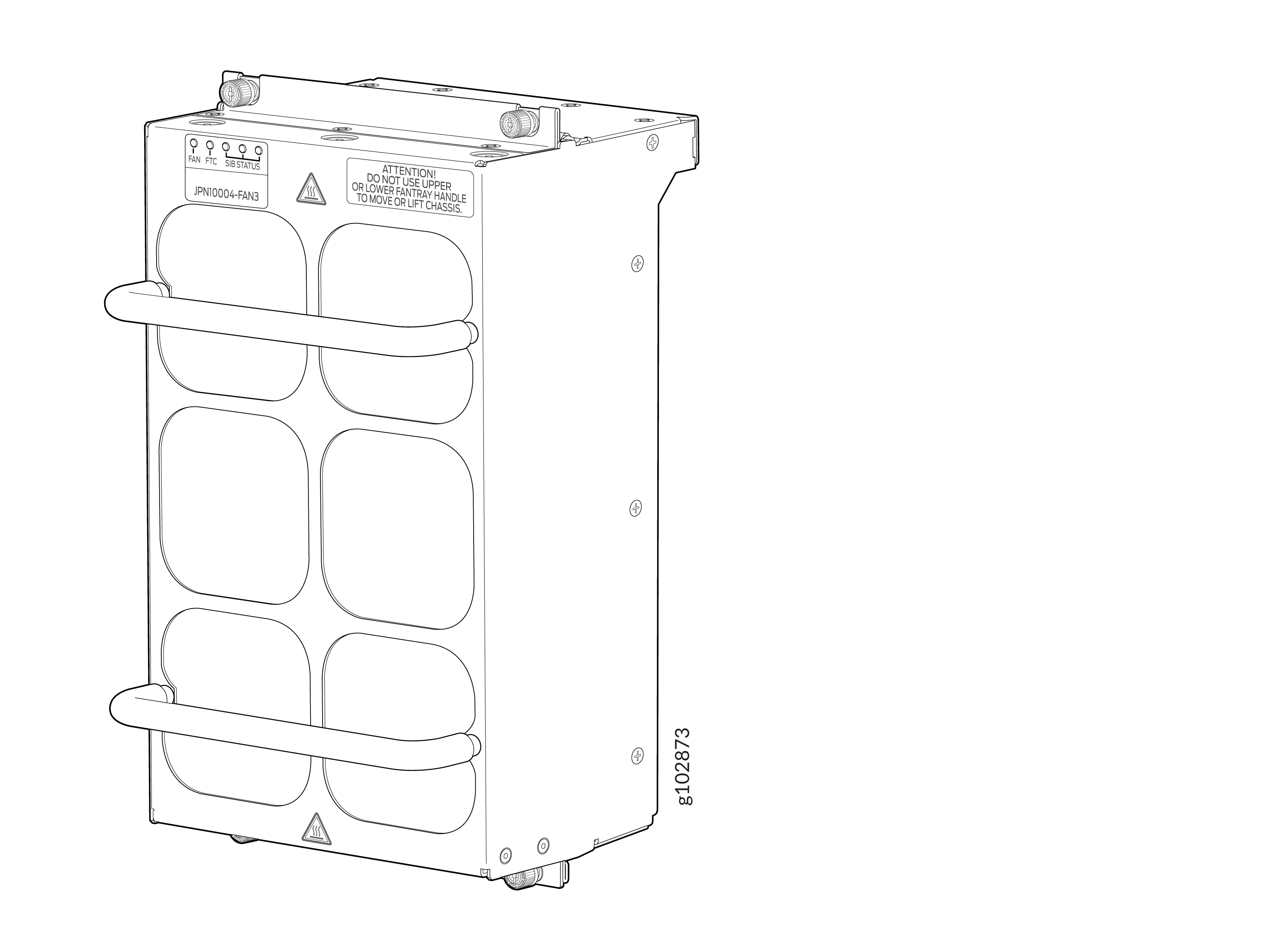
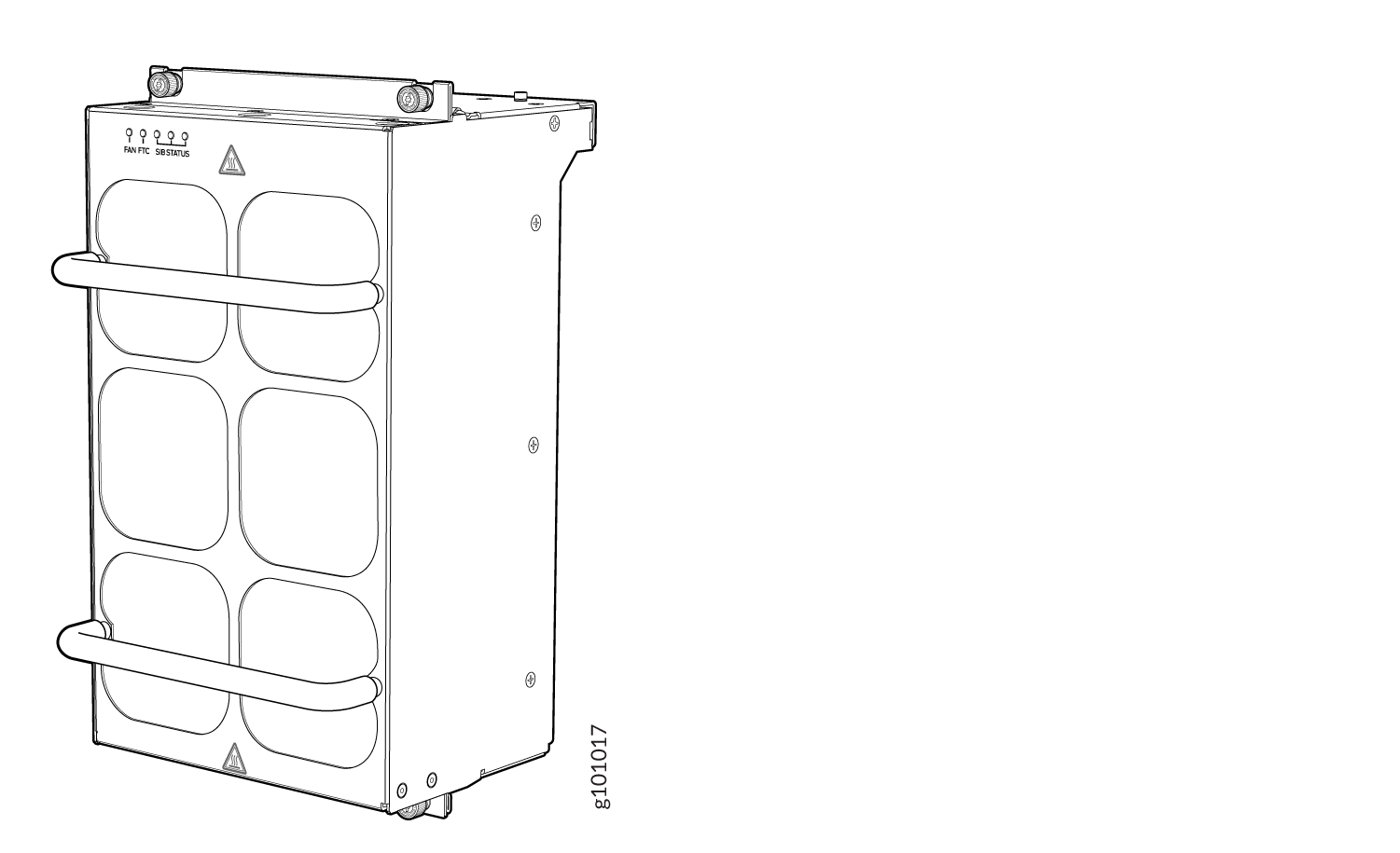
The JNP10004-FAN2 fan tray contains internal fans, a non-removable control board, and LEDs.
The two fan trays install vertically, side by side, next to the power supplies on the FRU side of the chassis. Two handles on each front faceplate facilitate handling of the fan tray. See Figure 2 and Figure 3.
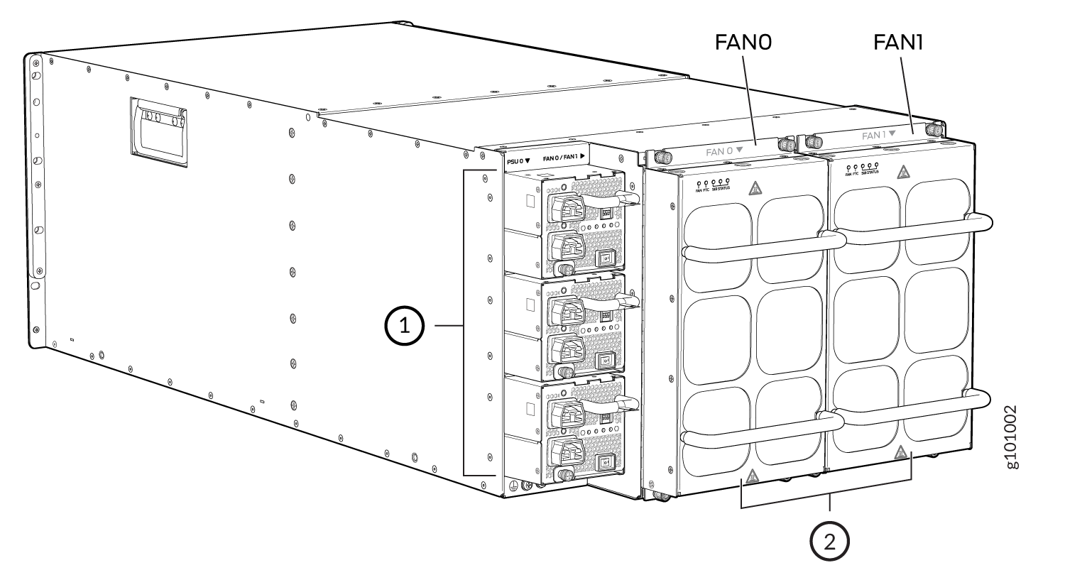
1 — Power supplies | 2 — Fan trays |
See Table 1 for the physical specifications of the fan trays.
|
Specification |
JNP10004-FAN3 |
JNP10004-FAN2 |
|---|---|---|
|
Corresponding fan tray controller model |
JNP10004-FTC3 |
JNP10004-FTC2 |
|
Number of fan modules per fan tray |
6 |
6 |
|
Number of fan modules per chassis |
12 |
12 |
|
Fan numbering |
0 through 11 |
0 through 11 |
|
Volume flow per fan tray at 100% at 72° F |
550 cubic feet per minute (CFM) |
475 cubic feet per minute (CFM) |
|
Volume flow per chassis at 100% at 72° F Note: This includes airflow through PSUs or Active
blanks.
|
1,260 CFM |
1080 CFM |
|
Introduced in Junos OS Release |
24.2R1-EVO |
20.3R1-EVO |
|
Compatible power supplies |
JNP10K-PWR-AC3, JNP10K-PWR-DC3, and JNP10K-PWR-AC3H |
JNP10K-PWR-AC2, JNP10K-PWR-DC2, JNP10K-PWR-AC3, JNP10K-PWR-DC3, and JNP10K-PWR-AC3H |
|
Height |
12.09 in. (30.7 cm) |
12.08 in. (30.68 cm) |
|
Width |
6.6 in. (16.8 cm) |
6.6 in. (16.8 cm) |
|
Depth |
5.88 in. (14.94 cm) without handles |
5.5 in. (13.97 cm) without handles, 6.85 in. (17.4 cm) with handles |
|
Weight |
14.4 lb (6.53 kg) |
9.8 lb (4.45 kg) |
The array of fans in both models operate as a single unit. If an individual fan in the array fails, the entire fan tray must be replaced. However, the fan tray continues to operate indefinitely and provides sufficient cooling even when a single rotor fails in a fan, provided the room temperature is within the operating range.
If you want to replace an existing fan tray while the router is running, remove only one fan tray. The router continues to operate for a limited time with a single operating fan tray without triggering a thermal alarm.
To avoid a thermal alarm, do not remove both fan trays while the router is operating.
The internal fan control board in each fan tray contains the LEDs for the associated fan tray controllers and the LEDs for the three SIBs directly behind the fan tray.
Fan Tray Controller
The PTX10004 supports two fan tray controllers to provide the control logic and power to hot-insert and hot-remove a fan tray:
-
JNP10004-FTC2—Supports JNP10004-FAN2 fan tray.
-
JNP10004-FTC3—Supports JNP10004-FAN3 and JNP10004-FAN2 fan trays; see Figure 4.
Table 2: Fan Tray Controller - Fan Tray Compatability Fan Tray Controller Compatible Fan Tray JNP10004-FTC2 JNP10004-FAN2 JNP10004-FTC3 JNP10004-FAN3, JNP10004-FAN2 Warning:Do not mix the fan tray controller models. Use only the supported fan tray model for each fan tray controller. See Table 3.
Do not use JNP10004-FTC2 with JNP10004-FAN3 fan tray.
Figure 4: Fan Tray Controller JNP10004-FTC2 or JNP10004-FTC3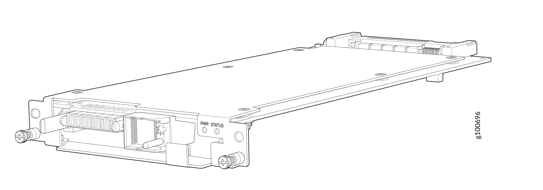
|
Specification |
JNP10004-FTC3 |
JNP10004-FTC2 |
|---|---|---|
|
Corresponding fan tray model |
JNP10004-FAN3 |
JNP10004-FAN2 |
|
Introduced in Junos OS Release |
24.2R1-EVO |
20.3R1-EVO |
|
Height |
1.5 in. (3.81 cm) |
1.5 in. (3.81 cm) |
|
Width |
6.5 in. (15.24 cm) |
6.5 in. (15.24 cm) |
|
Depth |
12.4 in. (31.5 cm) |
12.4 in. (31.5 cm) |
|
Weight |
1.1 lb (0.5 kg) |
1.1 lb (0.5 kg) |
The system continually monitors the temperature of critical parts across the chassis and
adjusts the chassis fan speed according to the temperature. Junos OS controls the fan
speed. Under normal operating conditions, the fans in the fan tray run at less than full
speed. If one fan tray controller fails or appears missing (such as
when a SIB is being replaced), the other fan tray controller sets the fans to full speed.
This allows the router to continue to operate normally as long as the remaining fans cool
the chassis sufficiently. Use the show chassis fan command to see the
status of individual fans and fan speed. The following examples show the fan status for a
system running JNP10004-FAN2 or JNP10004-FAN3.
user@system> show chassis fan
Item                      Status   % RPM     Measurement
      Fan Tray 0 Fan 0          Ok       59%       6300 RPM
      Fan Tray 0 Fan 1          Ok       55%       7500 RPM
      Fan Tray 0 Fan 2          Ok       60%       6450 RPM
      Fan Tray 0 Fan 3          Ok       54%       7350 RPM
      Fan Tray 0 Fan 4          Ok       59%       6300 RPM
      Fan Tray 0 Fan 5          Ok       55%       7500 RPM
      Fan Tray 0 Fan 6          Ok       59%       6300 RPM
      Fan Tray 0 Fan 7          Ok       54%       7350 RPM
      Fan Tray 0 Fan 8          Ok       60%       6450 RPM
      Fan Tray 0 Fan 9          Ok       54%       7350 RPM
      Fan Tray 0 Fan 10         Ok       59%       6300 RPM
      Fan Tray 0 Fan 11         Ok       54%       7350 RPM
      Fan Tray 1 Fan 0          Ok       59%       6300 RPM
      Fan Tray 1 Fan 1          Ok       55%       7500 RPM
      Fan Tray 1 Fan 2          Ok       59%       6300 RPM
      Fan Tray 1 Fan 3          Ok       55%       7500 RPM
      Fan Tray 1 Fan 4          Ok       60%       6450 RPM
      Fan Tray 1 Fan 5          Ok       55%       7500 RPM
      Fan Tray 1 Fan 6          Ok       59%       6300 RPM
      Fan Tray 1 Fan 7          Ok       54%       7350 RPM
      Fan Tray 1 Fan 8          Ok       60%       6450 RPM
      Fan Tray 1 Fan 9          Ok       54%       7350 RPM
      Fan Tray 1 Fan 10         Ok       54%       5850 RPM
      Fan Tray 1 Fan 11         Ok       50%       6750 RPM
To determine the cooling of all the components in the system, use the show
chassis environment command.
user@system> show chassis environment
Class Item                           Status     Measurement
Temp  PSM 0                          Ok         31 degrees C / 87 degrees F
      PSM 1                          Ok         30 degrees C / 86 degrees F
      CB 0 Intake A Temp Sensor      Ok         29 degrees C / 84 degrees F
      CB 0 Intake B Temp Sensor      Ok         30 degrees C / 86 degrees F
      CB 0 Exhaust A Temp Sensor     Ok         32 degrees C / 89 degrees F
      CB 0 Exhaust B Temp Sensor     Ok         33 degrees C / 91 degrees F
      CB 0 Middle Temp Sensor        Ok         34 degrees C / 93 degrees F
      CB 1 Intake A Temp Sensor      Ok         28 degrees C / 82 degrees F
      CB 1 Intake B Temp Sensor      Ok         28 degrees C / 82 degrees F
      CB 1 Exhaust A Temp Sensor     Ok         31 degrees C / 87 degrees F
      CB 1 Exhaust B Temp Sensor     Ok         31 degrees C / 87 degrees F
      CB 1 Middle Temp Sensor        Ok         33 degrees C / 91 degrees F
      Fan Tray 0 Inlet Temp Sensor   Ok         26 degrees C / 78 degrees F
      Fan Tray 0 Outlet Temp Sensor  Ok         32 degrees C / 89 degrees F
      Fan Tray 1 Inlet Temp Sensor   Ok         27 degrees C / 80 degrees F
      Fan Tray 1 Outlet Temp Sensor  Ok         32 degrees C / 89 degrees F
      FPC 3 BT-0 HBM-0 Temperature   Ok         53 degrees C / 127 degrees F
      FPC 3 BT-0 HBM-1 Temperature   Ok         54 degrees C / 129 degrees F
      FPC 3 BT-1 HBM-0 Temperature   Ok         53 degrees C / 127 degrees F
      FPC 3 BT-1 HBM-1 Temperature   Ok         53 degrees C / 127 degrees F
      FPC 3 BT-2 HBM-0 Temperature   Ok         53 degrees C / 127 degrees F
      FPC 3 BT-2 HBM-1 Temperature   Ok         55 degrees C / 131 degrees F
      FPC 3 BT-3 HBM-0 Temperature   Ok         60 degrees C / 140 degrees F
      FPC 3 BT-3 HBM-1 Temperature   Ok         57 degrees C / 134 degrees F
      FPC 3 BT-4 HBM-0 Temperature   Ok         54 degrees C / 129 degrees F
      FPC 3 BT-4 HBM-1 Temperature   Ok         54 degrees C / 129 degrees F
      FPC 3 BT-0 Temp Sensor 1       Ok         83 degrees C / 181 degrees F
      FPC 3 BT-0 Temp sensor 0       Ok         87 degrees C / 188 degrees F
      FPC 3 BT-1 Temp Sensor 0       Ok         79 degrees C / 174 degrees F
      FPC 3 BT-1 Temp Sensor 1       Ok         78 degrees C / 172 degrees F
      FPC 3 BT-2 Temp Sensor 0       Ok         81 degrees C / 177 degrees F
      FPC 3 BT-2 Temp Sensor 1       Ok         81 degrees C / 177 degrees F
      FPC 3 CPU Temperature          Ok         60 degrees C / 140 degrees F
      FPC 3 DDR4 A                   Ok         44 degrees C / 111 degrees F
      FPC 3 DDR4 B                   Ok         38 degrees C / 100 degrees F
      FPC 3 Intake-A Temp sensor     Ok         42 degrees C / 107 degrees F
      FPC 3 Intake-B Temp sensor     Ok         36 degrees C / 96 degrees F
      FPC 3 BT-3 Temp Sensor 0       Ok         86 degrees C / 186 degrees F
      FPC 3 BT-3 Temp Sensor 1       Ok         85 degrees C / 185 degrees F
      FPC 3 BT-4 Temp Sensor 0       Ok         72 degrees C / 161 degrees F
      FPC 3 BT-4 Temp Sensor 1       Ok         73 degrees C / 163 degrees F
      FPC 3 Exhaust-A Temp Sensor    Ok         53 degrees C / 127 degrees F
      FPC 3 Exhaust-B Temp Sensor    Ok         53 degrees C / 127 degrees F
      FPC 3 Exhaust-C Temp Sensor    Ok         48 degrees C / 118 degrees F
      FPC 3 PEX Temp Sensor          Ok         72 degrees C / 161 degrees F
      Unknown 0 FTC I2CS temp_sensor Ok         31 degrees C / 87 degrees F
      Unknown 1 FTC I2CS temp_sensor Ok         32 degrees C / 89 degrees F
      SIB 0 Exhaust-1 temp sensor    Ok         38 degrees C / 100 degrees F
      SIB 0 Exhaust-2 temp sensor    Ok         40 degrees C / 104 degrees F
      SIB 0 Intake-1 temp sensor     Ok         28 degrees C / 82 degrees F
      SIB 0 Intake-2 temp sensor     Ok         28 degrees C / 82 degrees F
      SIB 0 Intake-3 temp sensor     Ok         34 degrees C / 93 degrees F
      SIB 0 Exhaust-3 temp sensor    Ok         43 degrees C / 109 degrees F
      SIB 0 ZF1 temp sensor          Ok         56 degrees C / 132 degrees F
      SIB 0 Intake-4 temp sensor     Ok         32 degrees C / 89 degrees F
      SIB 0 PEXSW Temp Sensor        Ok         34 degrees C / 93 degrees F
      Routing Engine 0 CPU Temperature Ok       37 degrees C / 98 degrees F
Fan   Fan Tray 0 Fan 0               Ok         6450 RPM
      Fan Tray 0 Fan 1               Ok         7350 RPM
      Fan Tray 0 Fan 2               Ok         6450 RPM
      Fan Tray 0 Fan 3               Ok         7350 RPM
      Fan Tray 0 Fan 4               Ok         6300 RPM
      Fan Tray 0 Fan 5               Ok         7350 RPM
      Fan Tray 0 Fan 6               Ok         6300 RPM
      Fan Tray 0 Fan 7               Ok         7350 RPM
      Fan Tray 0 Fan 8               Ok         6450 RPM
      Fan Tray 0 Fan 9               Ok         7500 RPM
      Fan Tray 0 Fan 10              Ok         6450 RPM
      Fan Tray 0 Fan 11              Ok         7500 RPM
      Fan Tray 1 Fan 0               Ok         6300 RPM
      Fan Tray 1 Fan 1               Ok         7350 RPM
      Fan Tray 1 Fan 2               Ok         6300 RPM
      Fan Tray 1 Fan 3               Ok         7500 RPM
      Fan Tray 1 Fan 4               Ok         6450 RPM
      Fan Tray 1 Fan 5               Ok         7350 RPM
      Fan Tray 1 Fan 6               Ok         6300 RPM
      Fan Tray 1 Fan 7               Ok         7350 RPM
      Fan Tray 1 Fan 8               Ok         6300 RPM
      Fan Tray 1 Fan 9               Ok         7350 RPM
      Fan Tray 1 Fan 10              Ok         5700 RPM
      Fan Tray 1 Fan 11              Ok         6900 RPM
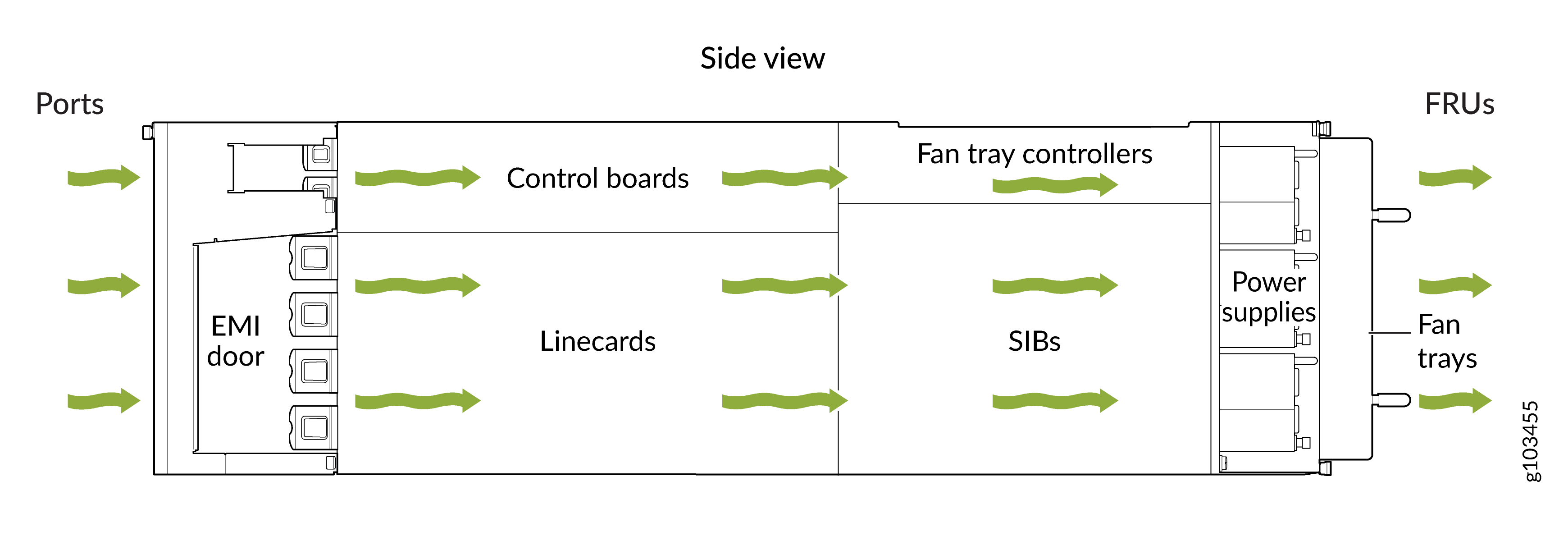
Airflow Direction in the PTX10004
The air intake to cool the chassis is located on the port (line card) side of the chassis. Air flows into the chassis from the ports in the Routing and Control Boards (RCBs) and line cards, through the Switch Interface Boards (SIBs), and exits from the fan trays and the power supplies. See Figure 5.
The fan tray continues to operate indefinitely and provide sufficient cooling even when a single rotor fails, provided the room temperature is within the operating range. You can check the status of fans by viewing the LEDs on each fan tray. See PTX10004 Fan Tray LEDs and Fan Tray Controller LEDs.
You cannot replace a single fan. If one or more fans fail, you must replace the entire fan tray.
In addition to the fans in the fan trays, there is an internal fan in each power supply that also helps to cool components, such as the line cards.
PTX10004 Fan Tray LEDs and Fan Tray Controller LEDs
Each fan tray has a set of LEDs, and each corresponding fan tray controller also has a set of LEDs.
Fan Tray LEDs
Each fan tray has a set of five LEDs that represent the status of the fans in the fan tray, the fan tray controller, and three of the Switch Interface Boards (SIBs). The LEDs are located on the top left corner of each fan tray. Figure 6 shows the location of the LEDs on JNP10004-FAN2 fan trays.
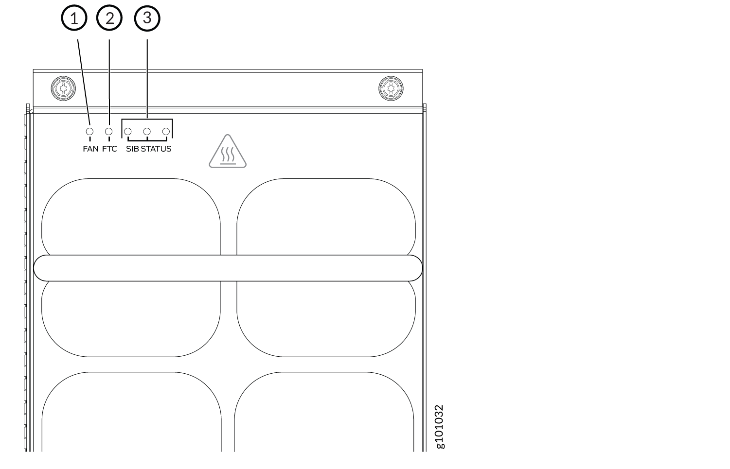
1 — Fan status LED | 3 — SIB status LEDs (SIB 0 through SIB 2 for the left fan tray and SIB 3 through SIB 5 for the right fan tray) |
2 — Fan tray controller status LED |
1 — Fan status LED | 3 — SIB status LEDs (SIB 0 through SIB 2 for the left fan tray and SIB 3 through SIB 5 for the right fan tray) |
2 — Fan tray controller status LED |
Table 4 describes the functions of the fan tray LEDs.
|
Name |
Color |
State |
Description |
|---|---|---|---|
|
FAN (fan status) |
Green |
On steadily |
All fans are operating normally. The system has verified that the fan tray is engaged, that the airflow is in the correct direction, and that all fans are operating correctly. |
|
Green |
Blinking |
The fan tray is starting up. The fan tray is not ready. |
|
|
Amber |
Blinking |
An error has been detected in one or more fans in the fan tray. Replace the fan tray as soon as possible. Either the fan has failed or it has become disconnected. To maintain proper airflow through the chassis, leave the fan tray installed in the chassis until you are ready to replace it. |
|
|
Amber |
Blipping |
Beacon is enabled. |
|
|
None |
Off |
The fan is not receiving power from the fan tray controller. All fans are off. |
|
|
FTC (fan tray controller status) |
Green |
On steadily |
Power is on. The fan tray controller is online and is operating normally. |
|
Amber |
Blinking |
An error has been detected in the fan tray controller. Replace the fan tray controller as soon as possible. The fan tray controller is located behind the fan tray above the SIBs. To maintain proper airflow through the chassis, leave the fan tray installed in the chassis until you are ready to replace the fan tray controller. |
|
|
Amber |
Blipping |
Beacon is enabled. |
|
|
None |
Off |
The fan tray controller is not receiving power. |
|
|
SIB Status (SIB 0 status) |
Green |
On steadily |
The left-most SIB in the chassis is online. |
|
Amber |
Blinking |
An error has been detected in SIB 0. Replace the SIB as soon as possible. The SIB is located behind the left fan tray and is the left-most SIB in the chassis. To maintain proper airflow through the chassis, leave the fan tray installed in the chassis until you are ready to replace the SIB. |
|
|
Amber |
Blipping |
Beacon is enabled. |
|
|
None |
Off |
The SIB is offline. |
|
|
SIB Status (SIB 1 status) |
Green |
On steadily |
The center SIB behind the left fan tray is online. |
|
Amber |
Blinking |
An error has been detected in SIB 1. Replace the SIB as soon as possible. The SIB is located behind the left fan tray and is the middle SIB in the group of 3. To maintain proper airflow through the chassis, leave the fan tray installed in the chassis until you are ready to replace the SIB. |
|
|
None |
Off |
The SIB is offline. |
|
|
SIB Status (SIB 2 status) |
Green |
On steadily |
The right-most SIB behind the left fan tray is online. |
|
Amber |
Blinking |
An error has been detected in SIB 2. Replace the SIB as soon as possible. The SIB is located behind the left fan tray and is the right-most SIB in the group of 3. To maintain proper airflow through the chassis, leave the fan tray installed in the chassis until you are ready to replace the SIB. |
|
|
Amber |
Blipping |
Beacon is enabled. |
|
|
None |
Off |
The SIB is offline. |
|
|
SIB Status (SIB 3 status) |
Green |
On steadily |
The left-most SIB behind the right fan tray is online. |
|
Amber |
Blinking |
An error has been detected in SIB 3. Replace the SIB as soon as possible. The SIB is located behind the right fan tray and is the left-most SIB of the group of 3. To maintain proper airflow through the chassis, leave the fan tray installed in the chassis until you are ready to replace the SIB. |
|
|
Amber |
Blipping |
Beacon is enabled. |
|
|
None |
Off |
The SIB is offline. |
|
|
SIB Status (SIB 4 status) |
Green |
On steadily |
The center SIB behind the right fan tray is online. |
|
Amber |
Blinking |
An error has been detected in SIB 4. Replace the SIB as soon as possible. The SIB is located behind the right fan tray and is the middle SIB in the group of 3. To maintain proper airflow through the chassis, leave the fan tray installed in the chassis until you are ready to replace the SIB. |
|
|
Amber |
Blipping |
Beacon is enabled. |
|
|
None |
Off |
The SIB is offline. |
|
|
SIB Status (SIB 5 status) |
Green |
On steadily |
The right-most SIB behind the right fan tray is online. |
|
Amber |
Blinking |
An error has been detected in SIB 5. Replace the SIB as soon as possible. The SIB is located behind the right fan tray and is the right-most SIB in the group of 3. To maintain proper airflow through the chassis, leave the fan tray installed in the chassis until you are ready to replace the SIB. |
|
|
Amber |
Blipping |
Beacon is enabled. |
|
|
None |
Off |
The SIB is offline. |
Fan Tray Controller LEDs
The fan tray controller LEDs are visible only when the associated fan tray is removed. The fan tray controller LEDs are located on the right of the controller panel. Figure 8 shows the location of the LEDs on the JNP10004-FTC2 fan tray controller faceplate.
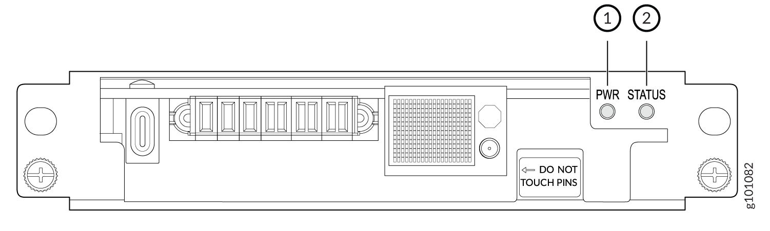
1 — Fan tray controller power | 2 — Fan tray controller status |
Table 5 describes the functions of the fan tray controller LEDs.
Name |
Color |
State |
Description |
|---|---|---|---|
PWR (fan tray controller power) |
Green |
On steadily |
The fan tray controller has power and is operating normally. |
Amber |
Blinking |
A power error has been detected in the fan tray controller. Replace the fan tray controller as soon as possible. To maintain proper airflow through the chassis, leave the fan tray installed in the chassis until you are ready to replace the fan tray controller. |
|
None |
Off |
The fan tray controller is not powered on or is not receiving power. |
|
STATUS (fan tray controller status) |
Green |
On steadily |
The fan tray controller is online and is operating normally. |
Amber |
Blinking |
An error has been detected in the fan tray controller. Replace the fan tray controller as soon as possible. To maintain proper airflow through the chassis, leave the fan tray installed in the chassis until you are ready to replace the fan tray controller. |
|
None |
Off |
The fan tray controller is not receiving power. |