Install and Remove PTX10004 Cooling System Components
The PTX10004 router has two independent, field-replaceable fan trays. To install or remove the fan trays and fan tray controller, see the following sections.
Install a PTX10004 Fan Tray
Before you begin to install a fan tray:
-
Ensure that you understand how to prevent ESD damage. See Prevention of Electrostatic Discharge Damage.
-
Ensure that you have the following parts and tools available to install a fan tray in a PTX10004 router:
-
Electrostatic discharge (ESD) grounding strap
-
A Phillips (+) screwdriver, number 1 or 2 (optional), for the captive screws
-
A replacement fan tray
-
One fan tray can be removed and replaced while the router is operating. Replace the fan tray as soon as possible to prevent thermal alarms and to prevent the chassis from overheating.
Each JNP10004-FAN2 or JNP10004-FAN3 fan tray is a hot-removable and hot-insertable field-replaceable unit (FRU); you can remove and replace the fan tray while the router is running without turning off power to the router or disrupting routing functions.
Each fan tray is installed vertically on the rear, or FRU side, of the chassis.
To install a PTX10004 fan tray:
-
Wrap and fasten one end of the ESD grounding strap around
your bare wrist and connect the other end of the strap to one of the
ESD points on the chassis (see Figure 1).
Figure 1: ESD Point on the Rear of the PTX10004
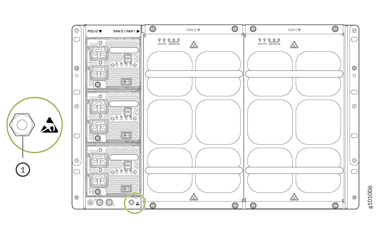 1—
1—ESD point
-
Tighten the captive screws with the Phillips screwdriver or your fingers until
the screws are finger tight. See Figure 2 and Figure 3.
Figure 2: Install the JNP10004-FAN2 Fan Tray in a PTX10004
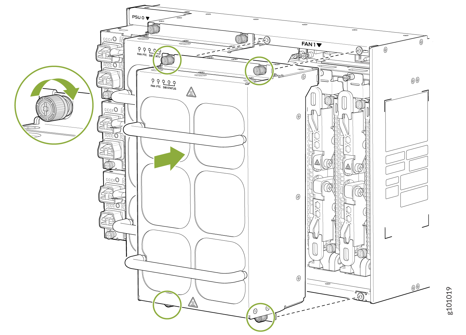 Figure 3: Install the JNP10004-FAN3 Fan Tray in a PTX10004
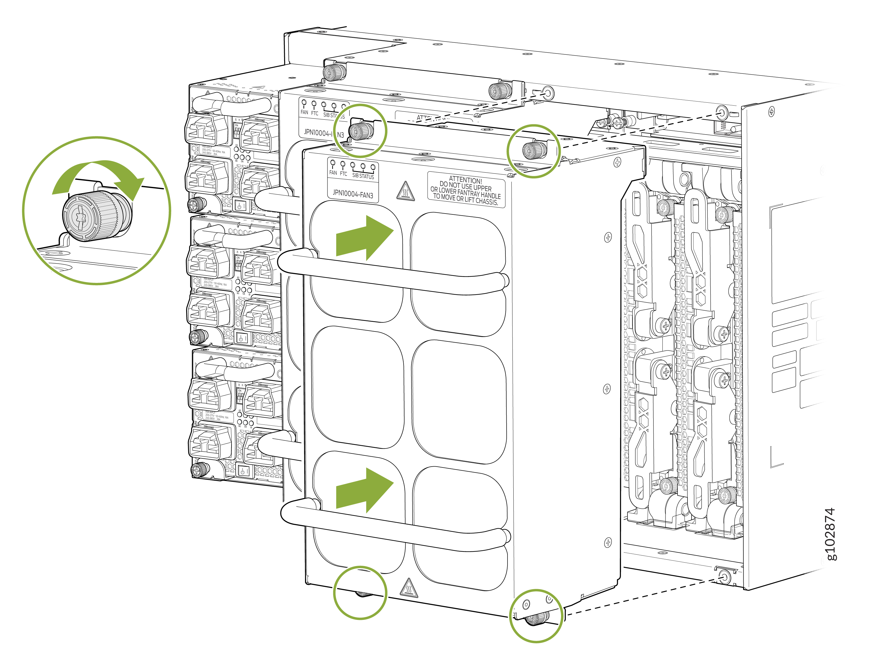
Remove a PTX10004 Fan Tray
Before you remove a fan tray:
-
Ensure that you understand how to prevent ESD damage. See Prevention of Electrostatic Discharge Damage.
-
Ensure that you have the following parts and tools available to remove a fan tray from a PTX10004:
-
Electrostatic discharge (ESD) grounding strap
-
Replacement fan tray
-
A Phillips (+) screwdriver, number 1 or 2 (optional), for the captive screws
-
-
Run the fans at 100 percent of max rated speed for 10 minutes before removing fan tray. Enter these commands from the primary RCB:
[edit] root@#
root@re0> request chassis fan tray 0 speed 100root@#root@re0> request chassis fan tray 1 speed 100
The PTX10004 chassis has two independent, field-replaceable fan trays (JNP10004-FAN2 or JNP10004-FAN3). Each fan tray is a hot-removable and hot-insertable FRU; you can remove and replace a single fan tray while the router is running without turning off power to the router or disrupting routing functions.
Do not remove the fan tray unless you have a replacement fan tray available.
If you remove a fan tray, you have a limited amount of time before a thermal alarm is raised. If you plan to replace one or more JNP10004-SF3 Switch Interface Boards (SIBS), make sure you calculate the round-trip of removing the fan tray, adding or replacing the SIBS, and installing the fan tray back into the chassis. To calculate the time allowed for replacing a fan tray, see Table 1.
|
Equivalent Ambient (degC) at sea level |
Time to Minor (Yellow) Alarm in Minutes |
Time to Major (Red) Alarm in Minutes |
||||
|---|---|---|---|---|---|---|
|
25 % Traffic |
50 % Traffic |
80 % Traffic |
25 % Traffic |
50 % Traffic |
80 % Traffic |
|
|
25 |
>10 min. |
4 min. 43 sec. |
2 min. 50 sec. |
>15 min |
6 min. 23 sec. |
3 min. 10 sec. |
|
30 |
3 min. 11 sec. |
2 min. 54 sec. |
1 min. 4 sec. |
3 min. 51 sec. |
3 min. 14 sec. |
2 min. 3 sec. |
|
40 |
1 min. 57 sec. |
1 min. 17 sec. |
58 sec. |
2 min. 18 sec. |
1 min. 37 sec. |
1 min. 10 sec. |
Each fan tray is installed vertically on the rear, or FRU side, of the chassis.
A single fan tray can be removed and replaced while the router is operating. However, if you remove both fan trays at the same time you’ll trigger a thermal alarm and the system will shut down. See Table 1.
To remove a PTX10004 fan tray:
-
Wrap and fasten one end of the ESD grounding strap around
your bare wrist and connect the other end of the strap to one of the
ESD points on the chassis (see Figure 4).
Figure 4: ESD Point on the Rear of the PTX10004
1—
ESD point
-
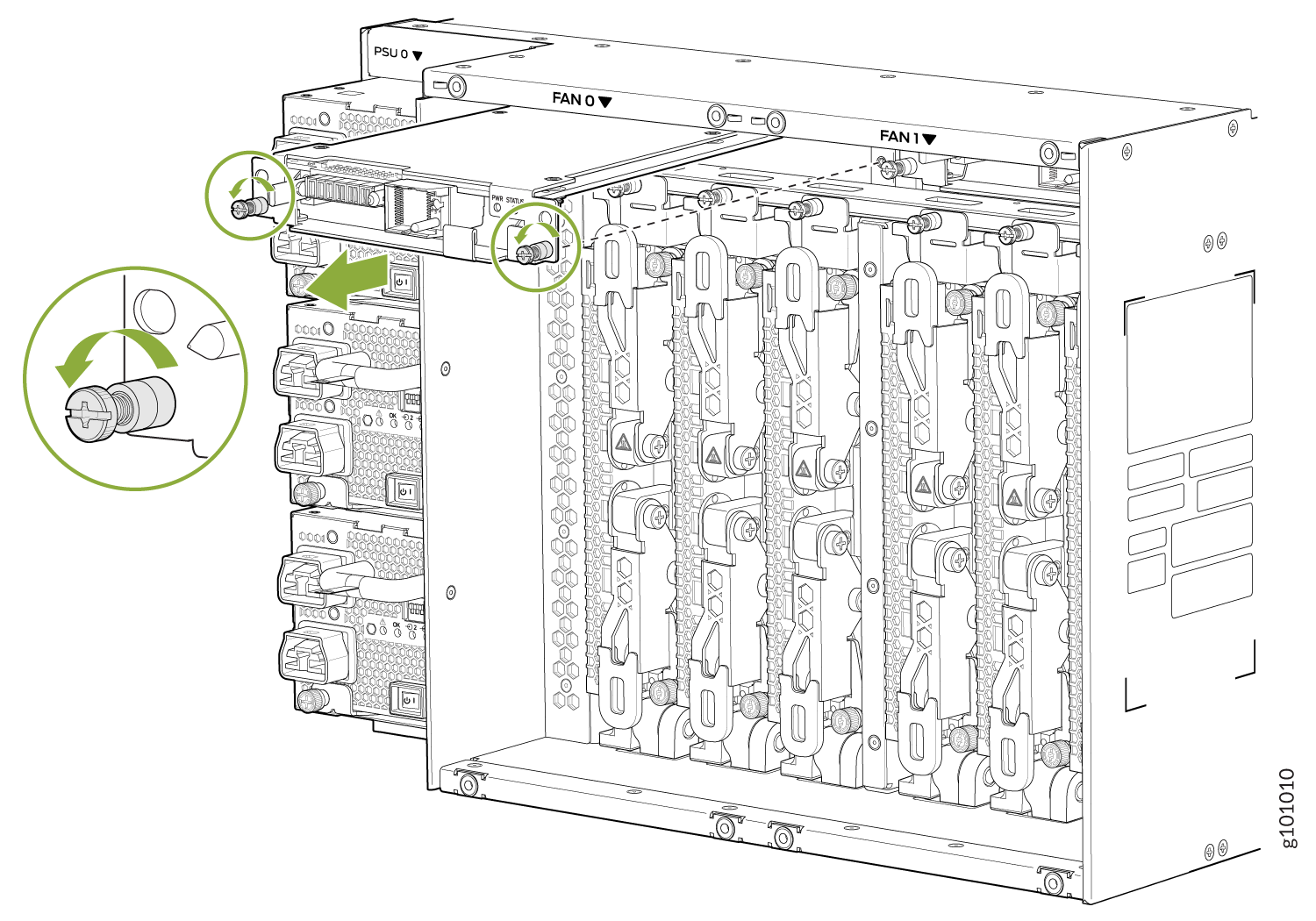
Grasp the top and bottom handles and pull the fan tray
out about 3 in. (7.6 cm). See Figure 5.
Figure 5: Remove a PTX10004 Fan Tray
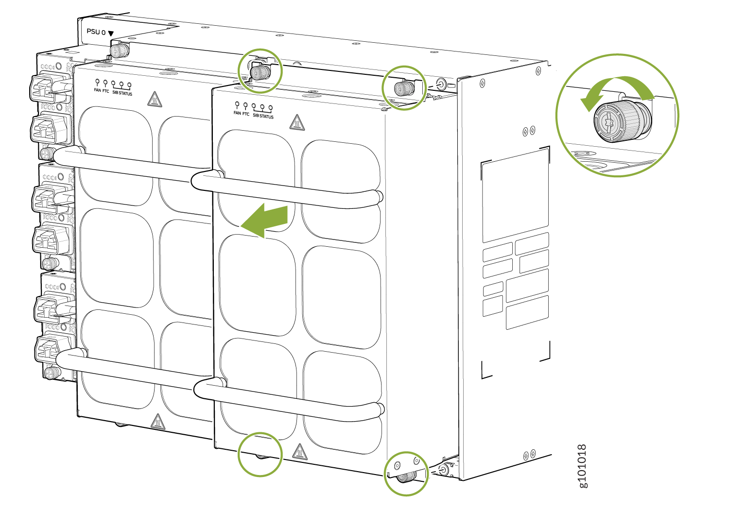 Figure 6: Remove the JNP10004-FAN3 PTX10004 Fan Tray
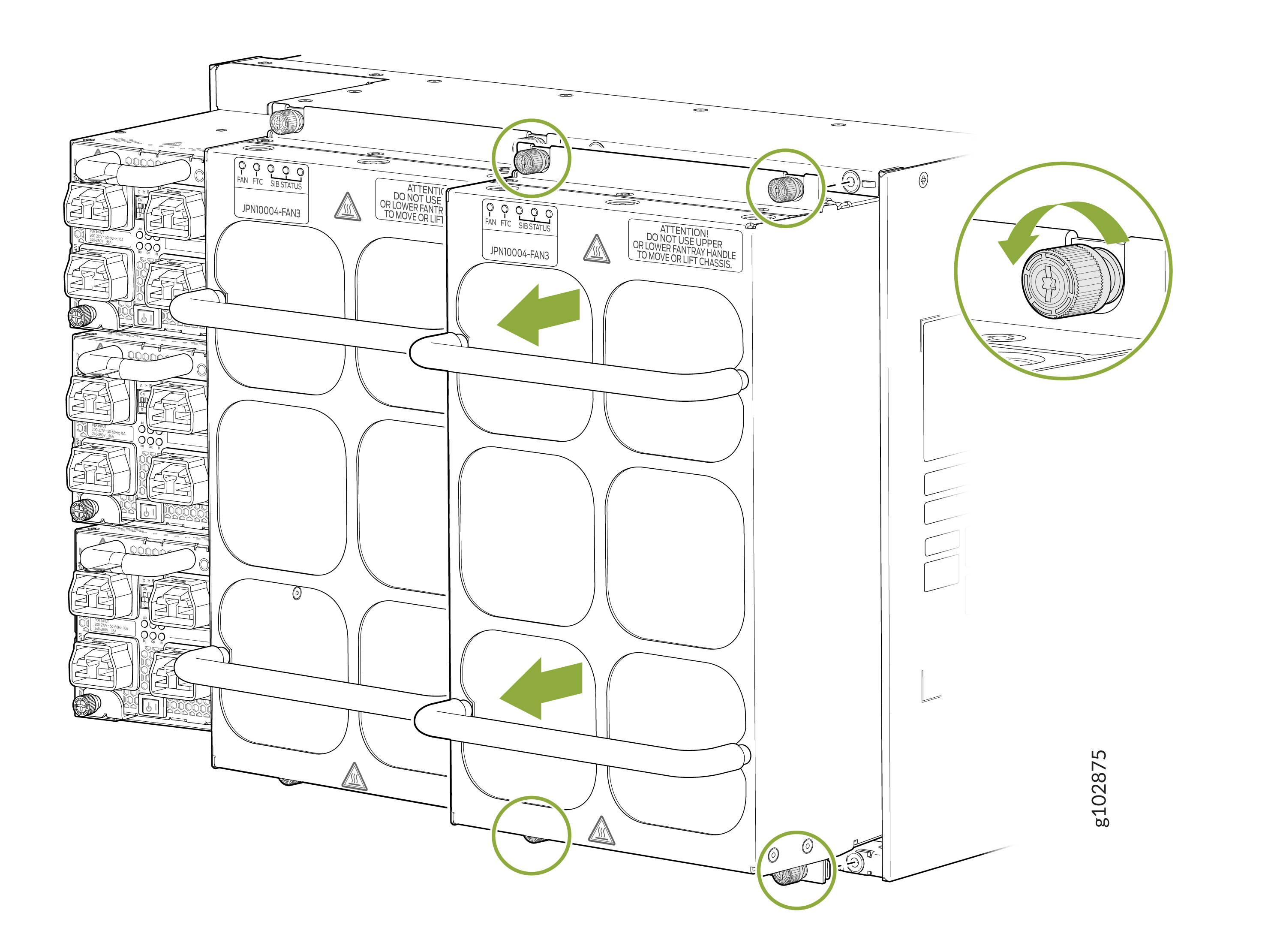
Install a PTX10004 Fan Tray Controller
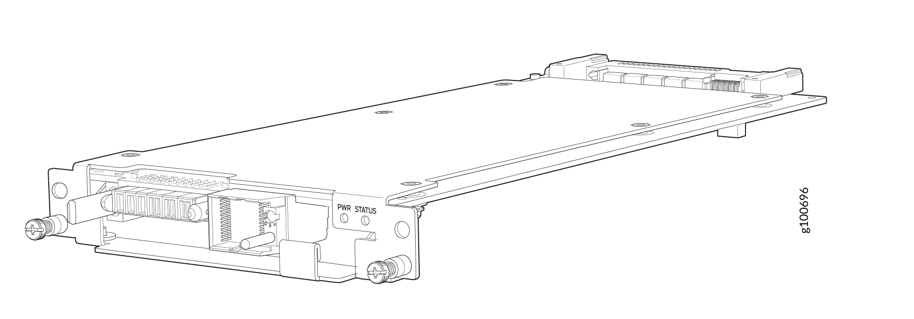
For each of the two fan trays, there is a corresponding JNP10004-FTC2 or JNP10004-FTC3 fan tray controller. Each controller is a hot-removable and hot-insertable field-replaceable unit (FRU); you can remove and replace one fan tray controller while the router is running without turning off power to the router or disrupting routing functions. See Figure 7.
Do not remove the fan tray controller unless you have a replacement controller available.
To install a fan tray controller, you must first remove the associated fan tray. With the fan tray removed, the fan tray controller is installed horizontally above the Switch Interface Boards (SIBs) at the top of the chassis.
Before you install a fan tray controller:
-
Ensure that you have removed the associated fan tray and fan tray controller. See Remove a PTX10004 Fan Tray and Remove a PTX10004 Fan Tray Controller.
-
Ensure that you understand how to prevent ESD damage. See Prevention of Electrostatic Discharge Damage.
-
Ensure that you have the following parts and tools available to install a fan tray controller into a PTX10004:
-
Electrostatic discharge (ESD) grounding strap
-
Replacement fan tray controller (JNP10004-FTC2)
-
A Phillips (+) screwdriver, number 1, for the captive screws (optional)
-
To install a fan tray controller:
-
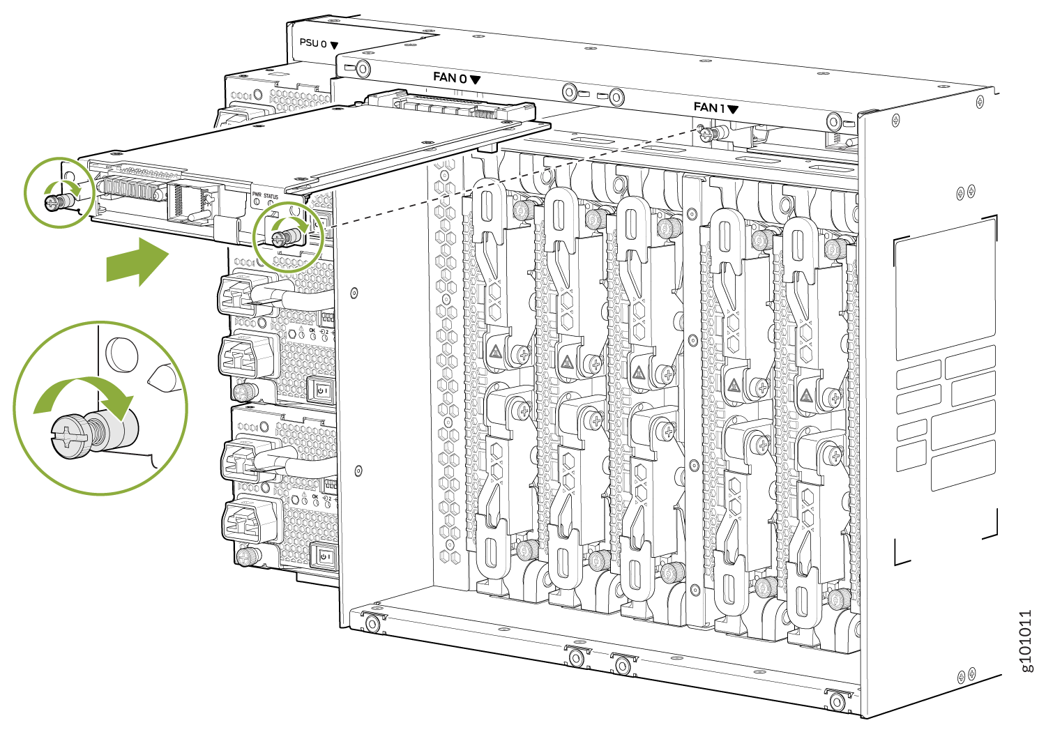
Carefully slide the fan tray controller into the fan tray
controller slot until it is flush with the mounting holes. See Figure 8.
Figure 8: Install the PTX10004 Fan Tray Controller
Remove a PTX10004 Fan Tray Controller
For each of the two fan trays, there is a corresponding JNP10004-FTC2 or JNP10004-FTC3 fan tray controller. Each fan tray controller is a hot-removable and hot-insertable field-replaceable unit (FRU); you can remove and replace one fan tray controller while the router is running without turning off power to the router or disrupting routing functions. See Figure 9.
Do not remove the fan tray controller unless you have a replacement controller available.
In order to access a fan tray controller, you must first remove the fan tray. With the fan tray removed, the fan tray controller is installed horizontally above the switch interface boards (SIBs) at the top of the chassis.
Before you remove a fan tray controller:
-
Ensure you understand how to prevent ESD damage. See Prevention of Electrostatic Discharge Damage.
-
Ensure that you have the following parts and tools available to remove a fan tray controller from a PTX10004:
-
Electrostatic discharge (ESD) grounding strap
-
An electrostatic bag or an antistatic mat
-
Replacement fan tray controller
-
A Phillips (+) screwdriver, number 1, for the captive screws (optional)
-
Both models of fan controller are removed using the same procedure.
-
Grasp the fan tray controller and pull it straight out
of the slot. See Figure 10.
Figure 10: Remove the JNP10004-FTC2 or JNP10004-FTC3 Fan Tray Controller