MX10008 System Overview
The MX10000 line of 5G Universal Routing Platforms give cloud and service providers the performance and scalability needed to outpace increased traffic demands. MX10008 provides 1-Gigabit Ethernet, 10-Gigabit Ethernet, 40-Gigabit Ethernet, 100-Gigabit Ethernet, or 400-Gigabit Ethernet modular solutions that support up to 76.8 Tbps of throughput. MX10008 provides redundancy and resiliency. All major hardware components including the power system, the cooling system, and the control board are fully redundant.
MX10008 Hardware Overview
Juniper Networks MX10008 Universal Routing Platform enables cloud and data center operators to transition from 10-Gigabit Ethernet and 40-Gigabit Ethernet networks to 100-Gigabit Ethernet high-performance networks. The 13 rack unit (13 U) modular chassis can provide 76.8 Tbps of throughput and 20 Bpps of forwarding capacity. The MX10008 router has eight slots for the line cards that can support a maximum of 768 100-Gigabit Ethernet ports (4x100 GbE breakout cables), 192 40-Gigabit Ethernet ports, 192 100-Gigabit Ethernet ports, or 192 400-Gigabit Ethernet ports. You can deploy the MX10008 router in an IP edge network.
You can deploy MX10008 in the edge of the network for the following functions:
-
Layer 3 Peering
-
Data Center Gateway
-
VPLS aggregation
-
Layer 3 Aggregation
-
Video Distribution
The MX10008 router is available in both base and redundant configurations for both AC and DC operation. MX10008 features front to back airflow (also know as airflow out or AFO).
- Benefits of the MX10008 Router
- Chassis Description
- MX10008 Routing and Control Board
- MX10008 Line Cards
- Switch Fabric Boards
- Cooling System
- MX10008 Power Supplies
- Software on MX10008
Benefits of the MX10008 Router
-
System capacity— MX10008 scales to 76.8 Tbps (153.6 Tbps half- duplex) in a single chassis, with support for up to 768 100-Gigabit Ethernet (4x100 GbE breakout cables), 192 40-Gigabit Ethernet, 192 100-Gigabit Ethernet interfaces, or 192 400-Gigabit Ethernet ports.
-
Full-scale IP and MPLS routing—MX10008 delivers the distributed peering scale of 12 million entries with nonstop active routing (NSR) and 13 million entries without NSR in the forwarding information bases (FIBs, also known as forwarding table), and 80 million routing information base entries (RIBs, also known as routing tables).
-
Source Packet Routing in Networking (SPRING)—SPRING on MX10008 provides additional flexibility per packet source. SPRING provides features such as network path and node protection to support MPLS fast reroute (FRR) mechanisms, enhanced network programmability, OAM functionality, simplified network signaling, load balancing, and traffic engineering functions.
-
Always-on infrastructure base—MX10008 is engineered with full hardware redundancy for cooling, switch fabric, and host subsystems—Routing and Control Boards (RCBs)—allowing service providers to meet stringent service-level agreements across the core.
-
Nondisruptive software upgrades—The Junos operating system on MX10008 supports high availability (HA) features such as graceful Routing Engine switchover (GRES), nonstop active routing (NSR), and unified in-service software upgrade (unified ISSU), providing software upgrades and changes without disrupting network traffic.
Chassis Description
MX10008 is 13 U tall. Up to three MX10008 routers can fit in a standard 39 U rack with adequate cooling and power. All key MX10008 router components are field-replaceable units (FRUs). Figure 1 illustrates the key components visible from the front of the chassis.
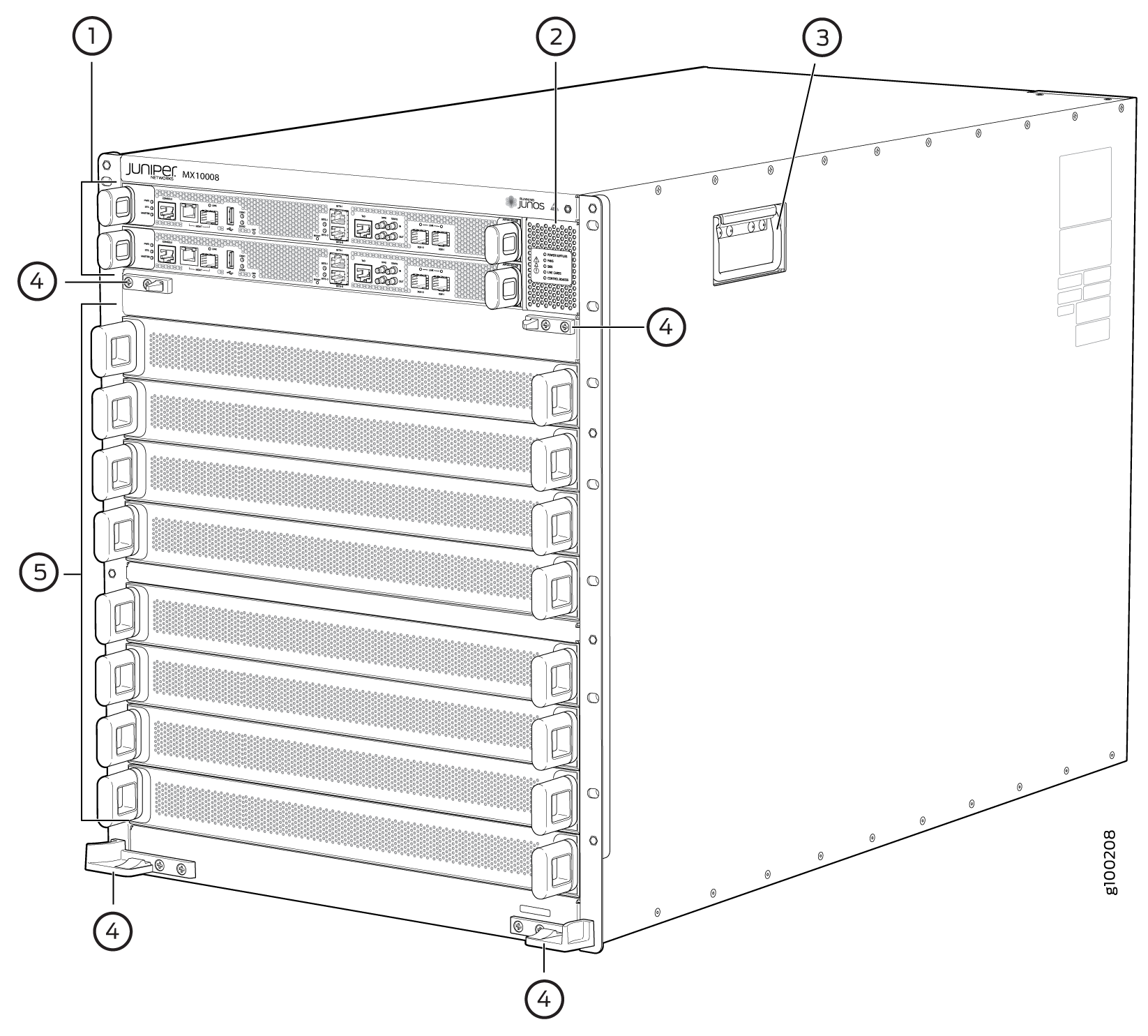
1 — Routing and Control Boards | 4 — Installation holes for the front panel |
2 — Status LED panel | 5 — Line card slots 0-7 (numbered top to bottom) |
3 — Handles |
Some chassis ship with an enhanced power bus to support the power needs of higher wattage line cards. Chassis with the enhanced power bus have a modified Status Panel (see MX10008 Status Panel LEDs).
Figure 2 illustrates the components that are visible from the rear of the chassis.
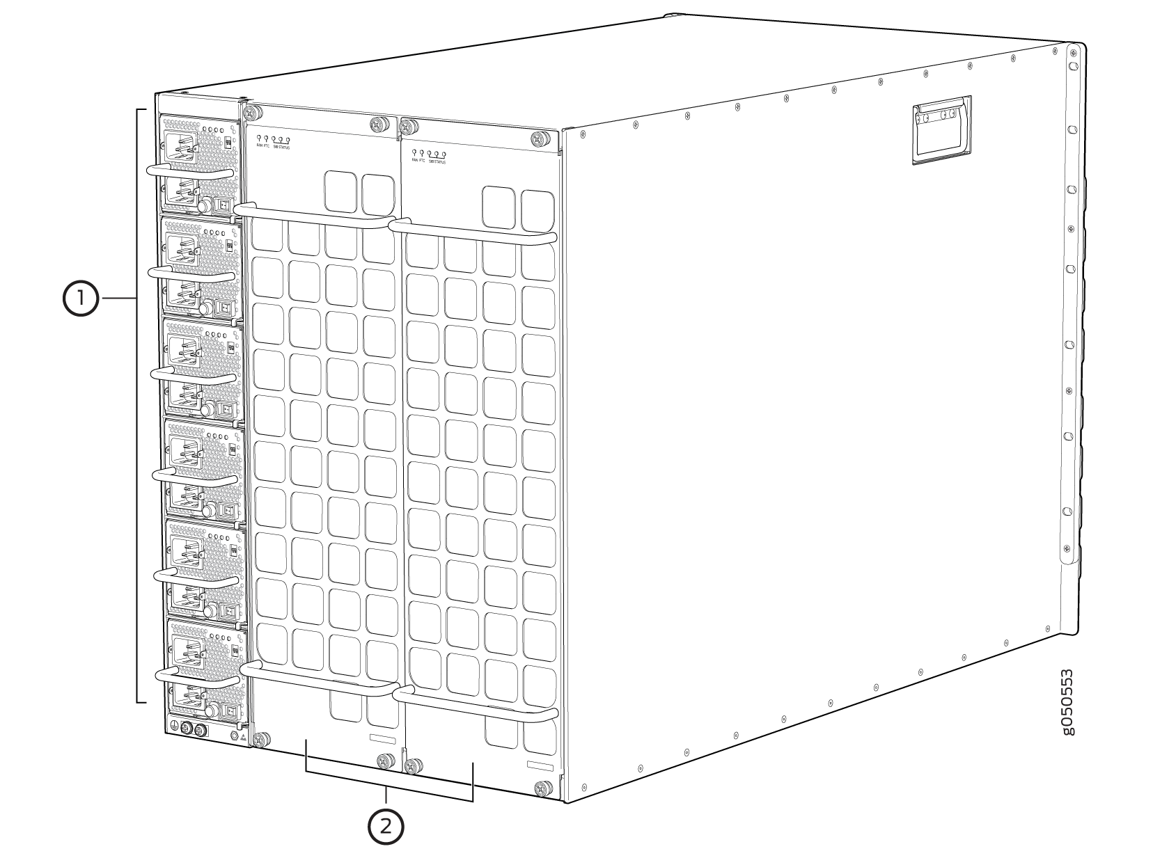
1 — AC or DC power supplies | 2 — Fan trays with redundant fans |
Figure 3 illustrates the components that are internal to the chassis.
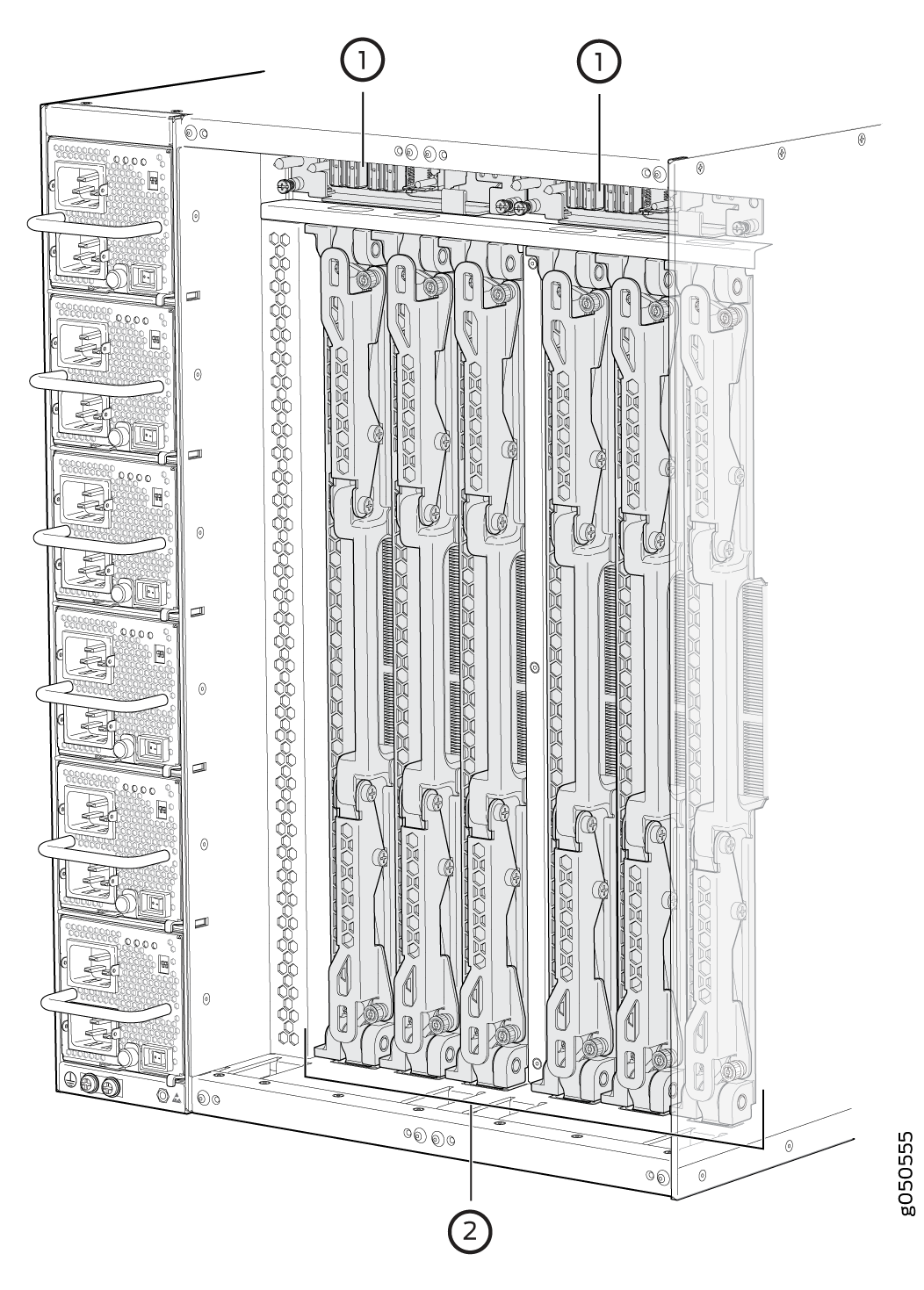
1 — Fan tray controllers | 2 — Switch fabric boards (SFBs) |
See MX10008 Chassis Physical Specifications and Field-Replaceable Units in an MX10008.
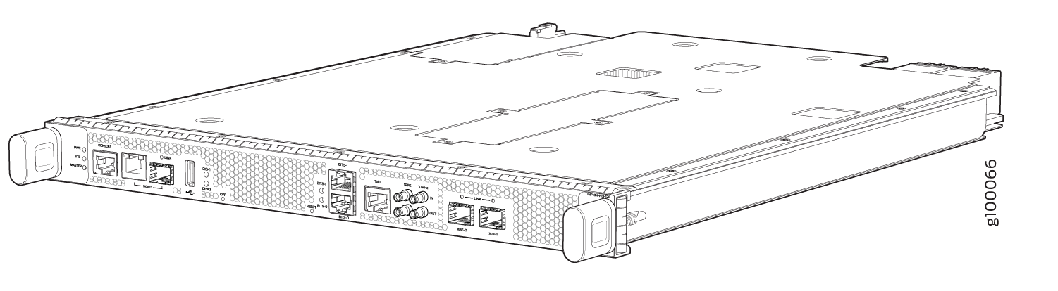
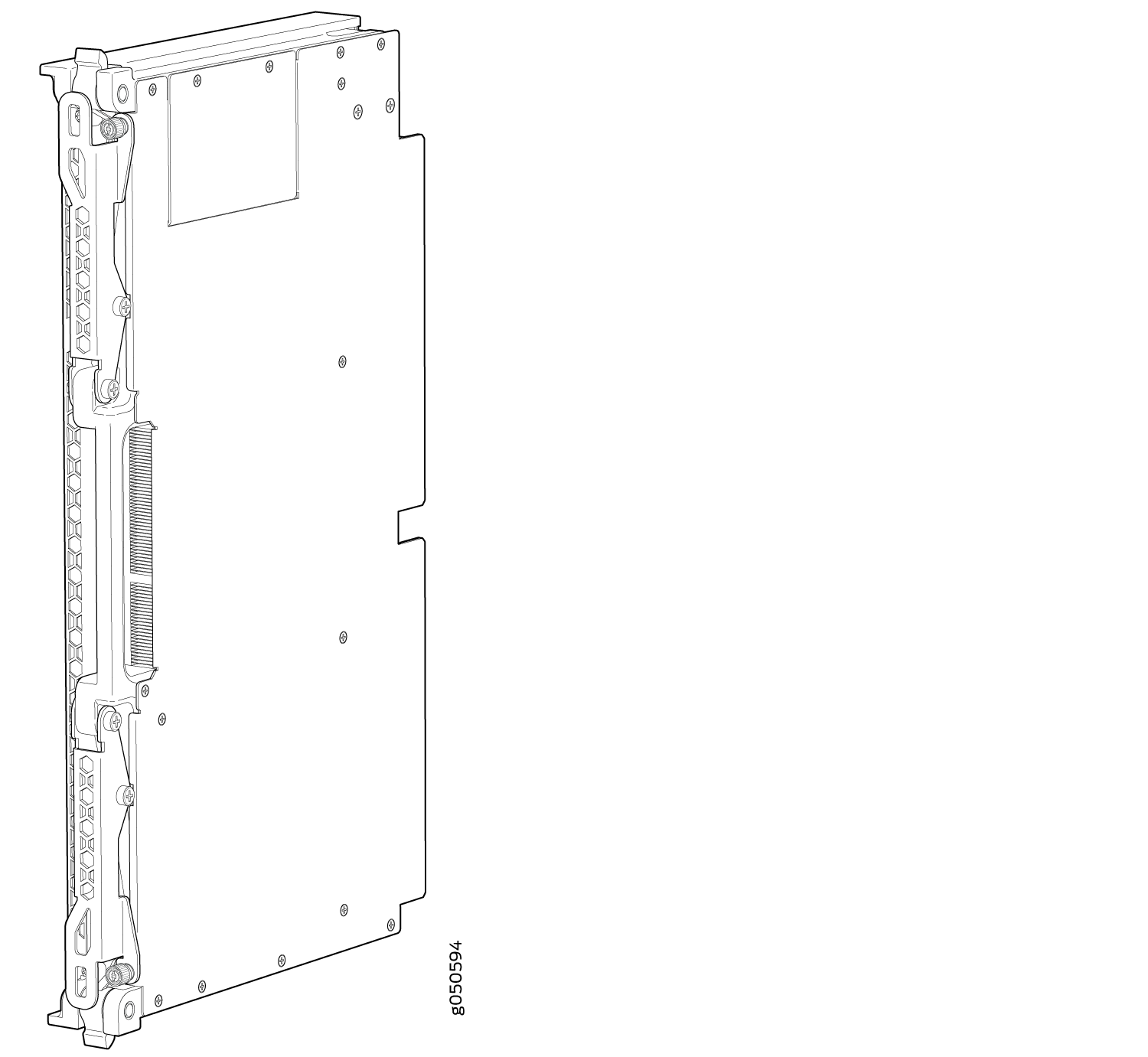
MX10008 Routing and Control Board
The Routing and Control board (RCB) (see Figure 4) contains a Routing Engine and is responsible for the system management and control in the MX10008. See MX10008 Routing and Control Board Description. RCBs are FRUs that are installed in the front of the chassis in the slots labeled CB0 and CB1. The base configuration has a single RCB while the fully redundant configuration has two RCBs. The RCB also contains Precision Time Protocol ports and two Media Access Control Security (MACsec) capable ports (see MX10008 Components and Configurations).
MX10008 Line Cards
MX10008 has eight horizontal line card slots and supports line rate for each line card. The line cards combine a Packet Forwarding Engine and Ethernet interfaces enclosed in a single assembly. Line cards are FRUs that can be installed in the line card slots labeled 0 through 7 (top to bottom) on the front of the chassis. All line cards are hot-removable and hot-insertable. After the hot insertion, the line card comes online automatically.
The MX10008 router supports the following line cards:
-
MX10K-LC2101—This line card provides a maximum bandwidth of 2.4Tbps and has six Packet Forwarding Engines, each providing a maximum bandwidth of up to 400 Gbps. The MX10K-LC2101 line card can support 24 100-Gigabit Ethernet ports with a 28-Gbps quad smallform-factor pluggable (QSFP28) transceiver, or 24 40-Gigabit Ethernet ports with a QSFP transceiver. The MX10K-LC2101 line cards also support 10-Gigabit Ethernet interfaces. For 10-Gigabit Ethernet, you must configure the port using the channelization command. Because there is no port-groups option for the 100-Gigabit Ethernet line card, you must use individual port channelization commands.
Figure 5 shows the MX10K-LC2101 line card.
Figure 5: MX10K-LC2101 Line Card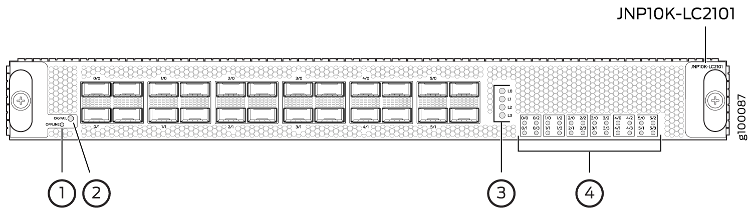 1—
1—OFFLINE button
3—Lane LEDs
2—OK/FAIL LED
4—Port LEDs
-
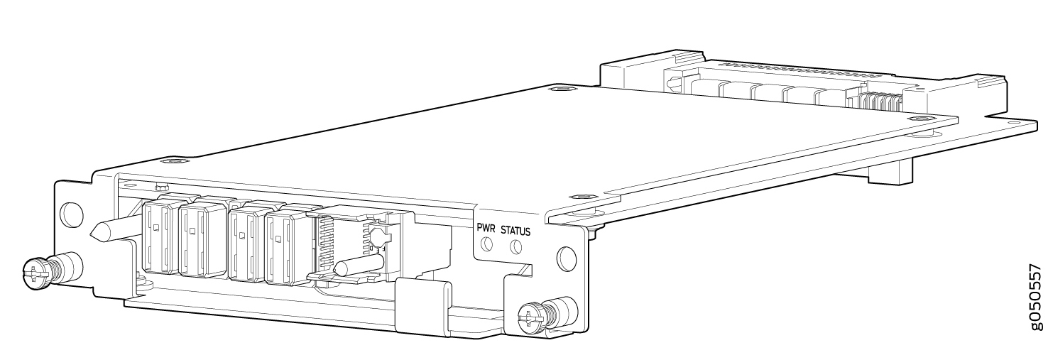
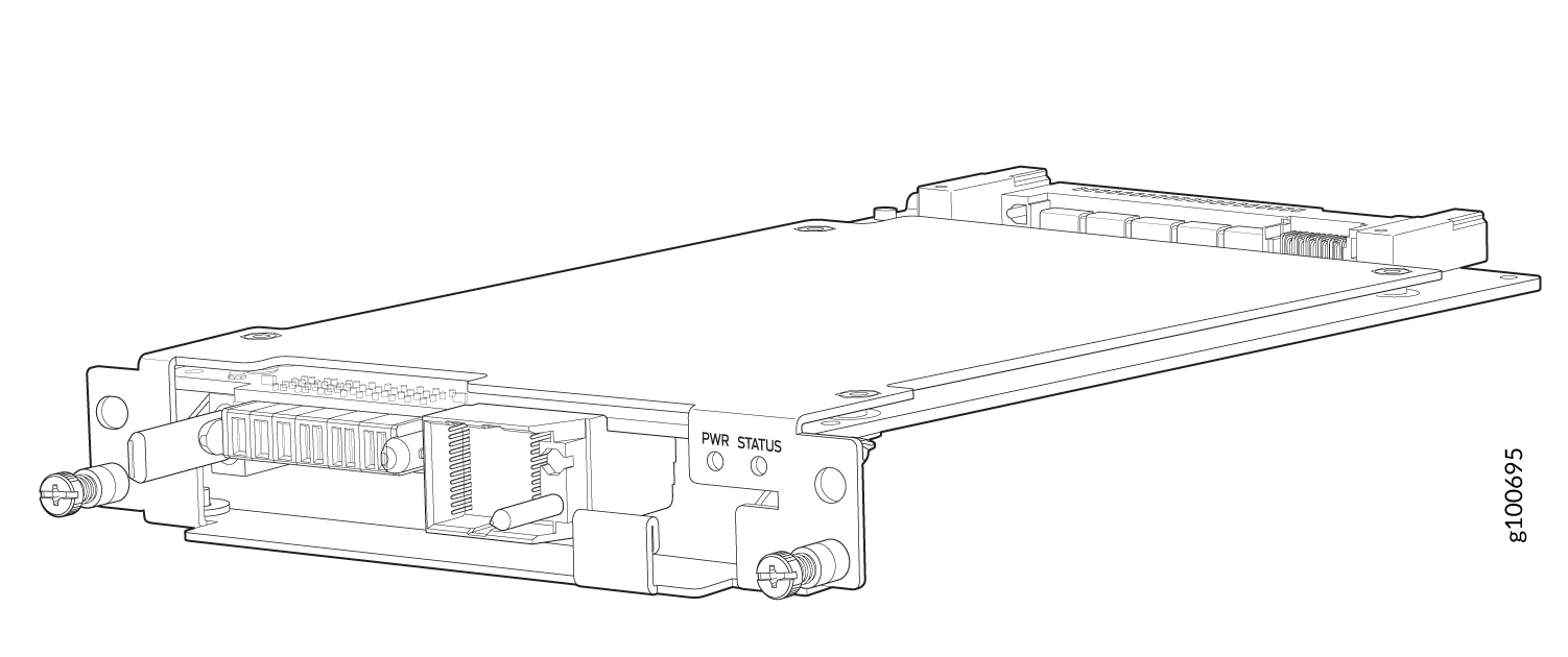
MX10K-LC480—The MX10K-LC480 line card is a fixed configuration MPC with 48 ports. Each port supports a speed of 10 Gbps or 1 Gbps, providing the line card a maximum bandwidth of 480 Gbps. The MX10K-LC480 has two Packet Forwarding Engines, each providing a maximum bandwidth of up to 240 Gbps.
Figure 6 shows MX10K-LC480 line card.
Figure 6: MX10K-LC480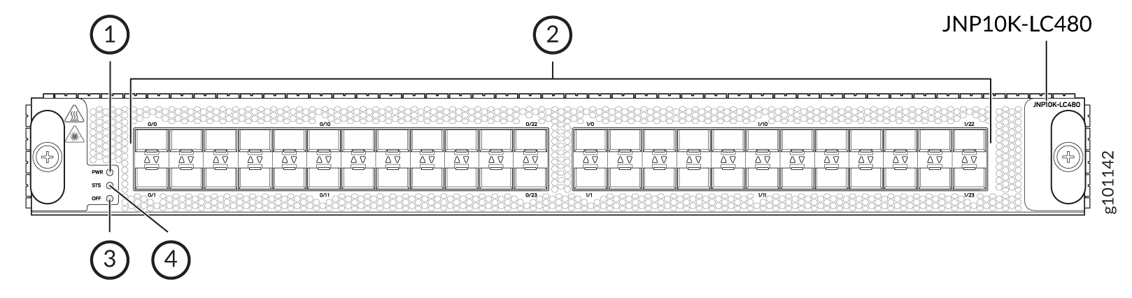 1—
1—Power (PWR) LED.
3—Offline/online (OFF) button.
2—Port LEDs.
4—Status (STS) LED.
-
MX10K-LC9600 Line Card—The MX10K-LC9600 (Model number: JNP10K-LC9600) is a fixed-configuration 24-port line card, which provides a line rate throughput of 9.6 Tbps. The line card has twenty-four QSFP-DD ports, each capable of supporting a maximum speed of 400 Gbps.
The MX10K-LC9600 line card combines Packet Forwarding Engine based on Juniper Networks custom ASICs. The line card has six forwarding ASICs, each hosting two Packet Forwarding Engines. The line card has 12 Packet Forwarding Engines, each providing a maximum bandwidth of 800 Gbps.
Figure 7: MX10K-LC9600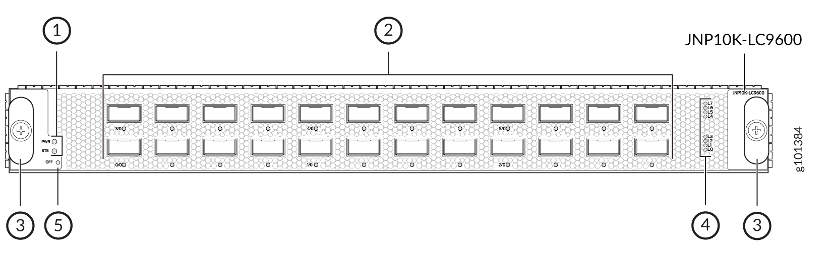 1—
1—QSPF Ports
3—Lane LEDs
2—Ejector Handles
4—PWR, STS, and OFF LEDs
-
The MX10K-LC4800 line card (model number: JNP10K-LC4800) is a fixed-configuration 44-port line card that provides a line-rate throughput of 4.8 Tbps. This line card supports 100-Gigabit Ethernet (100GbE) and 400GbE deployments.
Figure 8: MX10K-LC4800 Line Card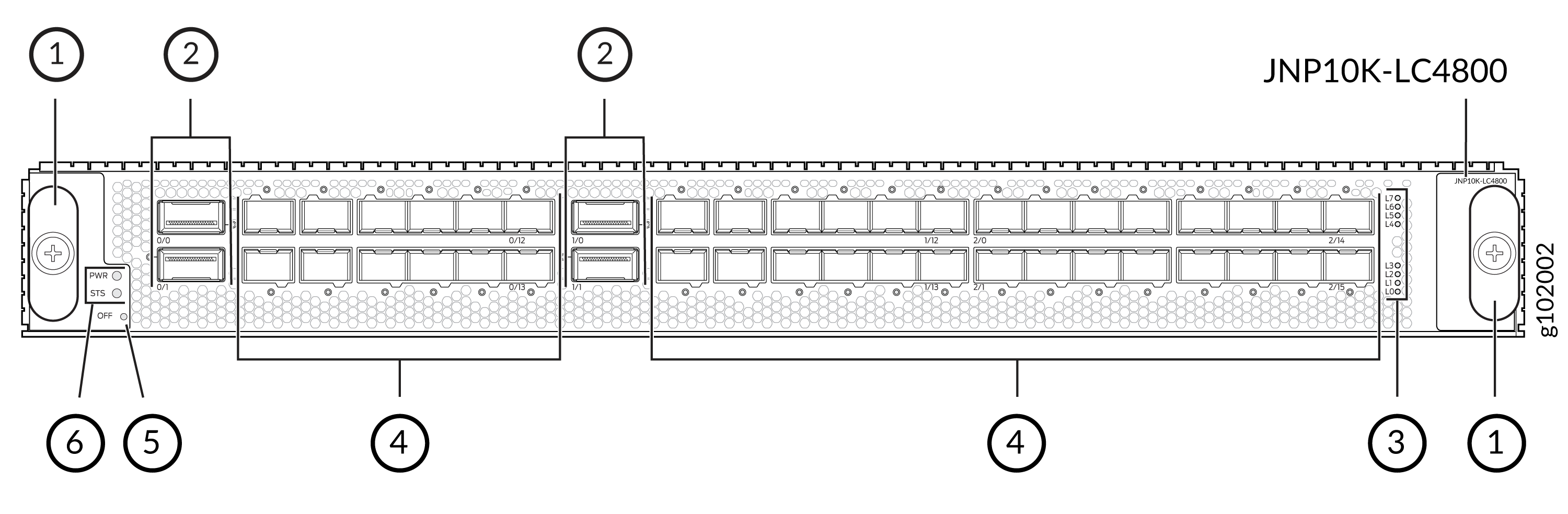 1—
1—Ejectors
4—SFP56-DD ports
2—QSFP56-DD ports
5—OFF (offline) button
3—Lane LEDs
6—PWR and STS LEDs
-
The MX10K-LC4802 line card (model number: JNP10K-LC4802) is a fixed-configuration 36-port line card that provides a line-rate throughput of 4.8 Tbps. This line card supports 100-Gigabit Ethernet (100 GbE) and 400 GbE deployments.
Figure 9: MX10K-LC4802 Line Card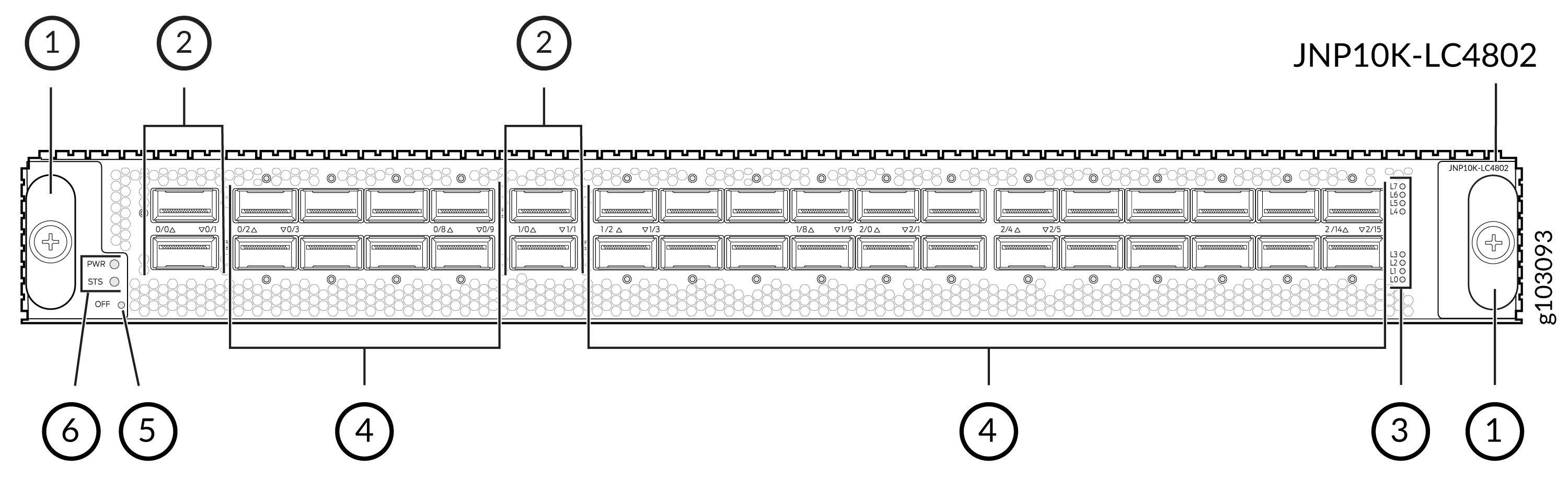 1—
1—Ejectors
4—QSFP28 ports
2—QSFP56-DD ports
5—OFF (offline) button
3—Lane LEDs
6—PWR and STS LEDs
Switch Fabric Boards
Switch Fabric Boards (SFBs) provide the necessary switching functionality to an MX10008 router. SFBs are installed between the line cards and the fan trays inside of the chassis.
There are two models of SFBs: the JNP10008-SF and the JNP10008-SF2. SFBs installed must be of the same model type in a running chassis. On both models, the SFB has eight connectors that match and connect to a connector on one of the eight line cards, eliminating the need for a backplane.
In a MX10008 router you can install five JNP10008-SFs for the necessary switching functionality and the sixth JNP10008-SF to provide n+1 redundancy. When all the six JNP10008-SFs are installed, the MX10008 router has a net switching capacity of 2.4Tbps (bidirectional)
In a MX10008 router if you want to install MX10K-LC9600 line card you must install all the six JNP10008-SF2s to achieve 153.6Tbps (bidirectional) switching capacity. The MX10K-LC9600 line cards are not compatible with the JNP10008-SFs. See MX10008 Switch Fabric Board Description.
Cooling System
The cooling system in an MX10008 router consists of two hot-removable and hot-insertable FRU fan trays and two fan tray controllers.
Three fan tray models (JNP10008-FAN. JNP10008-FAN2, and JNP10008-FAN3) and their associated fan tray controllers (JNP10008-FAN-CTRL, JNP10008-FTC2, and JNP10008-FTC3) are available. The fan trays install vertically on the rear of the chassis and provide front to back chassis cooling. For model differences, see MX10008 Cooling System and Airflow.
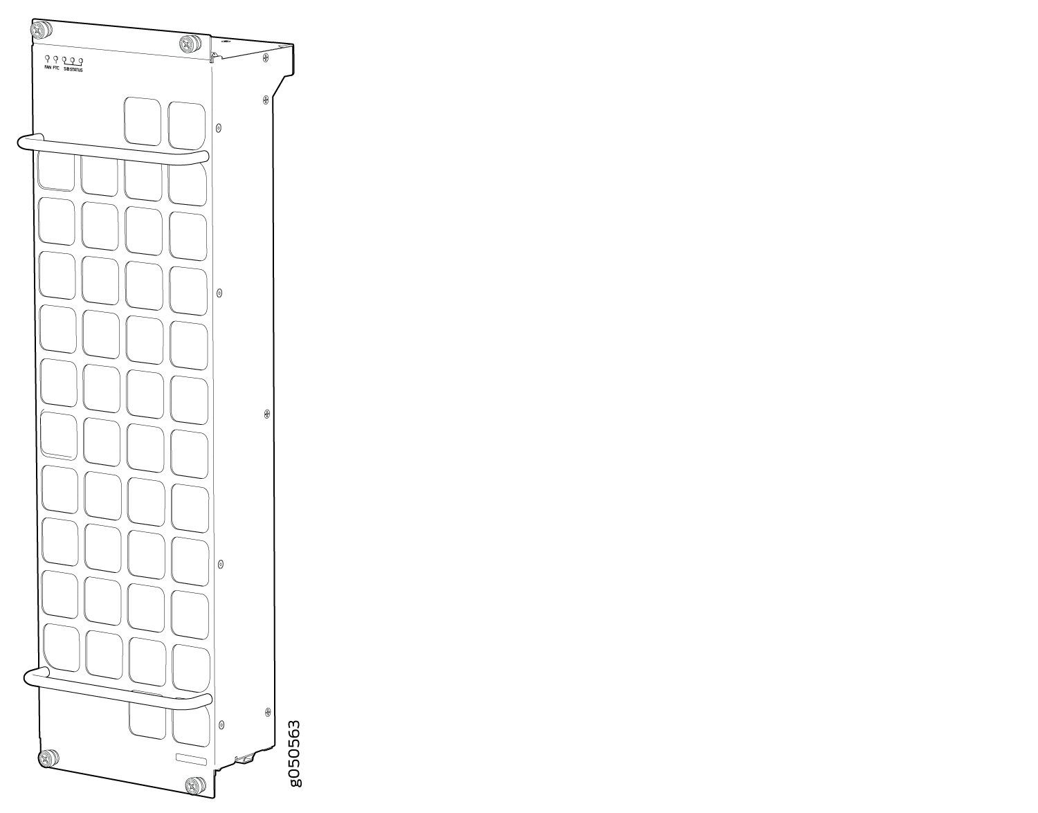
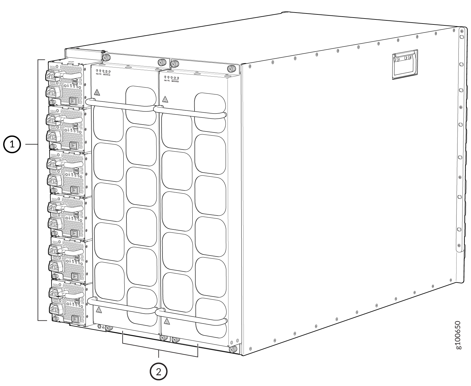
1 — Power Supplies | 2 — JNP10008-FAN2 - Fan trays |
MX10008 Power Supplies
Power supplies for the MX10008 router are fully redundant, load-sharing, and hot-removable and hot-insertable FRUs. Each MX10008 router with a base configuration has three power supplies; redundant configurations hold a maximum of six AC, high-voltage alternating current (HVAC), DC, or high-voltage direct current (HVDC) power supplies. Each power supply has an internal fan for cooling. See Figure 15 through Figure 19.
Do not mix power supply models in the same chassis in a running environment. DC and HVDC can coexist in the same chassis during the hot swap of DC for HVDC.
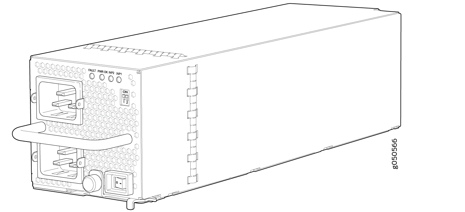
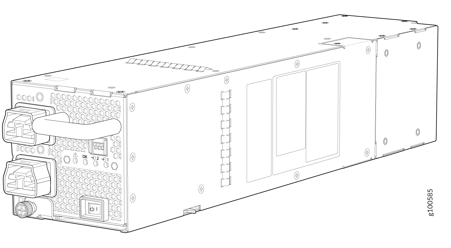
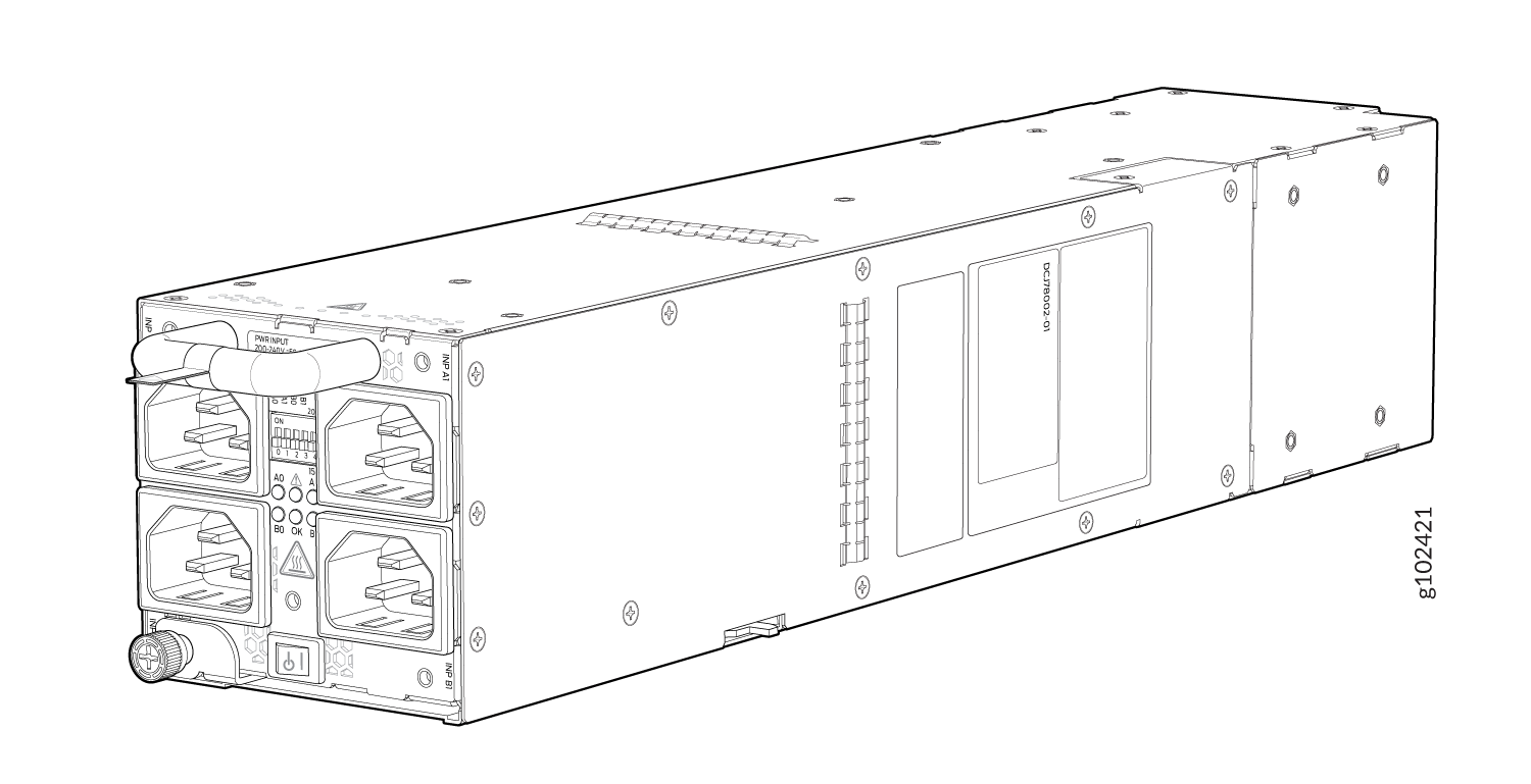
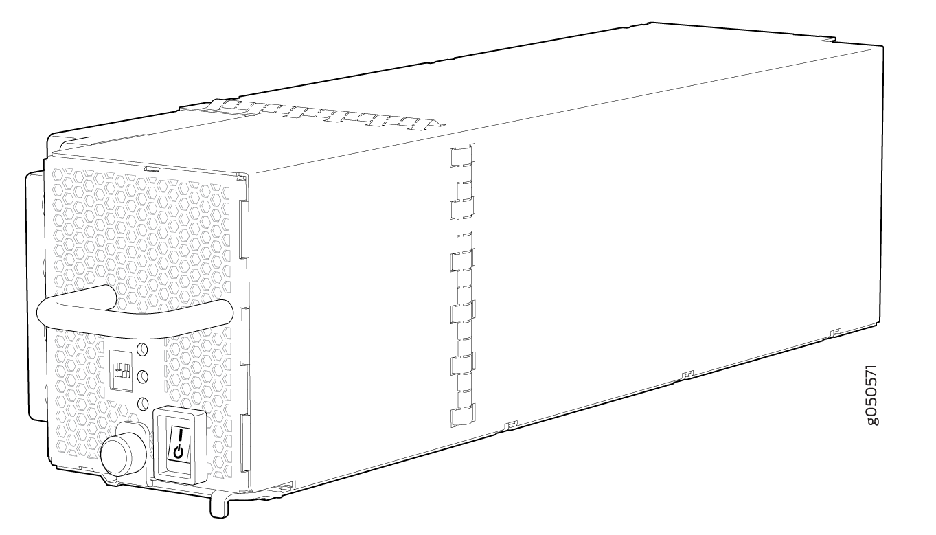
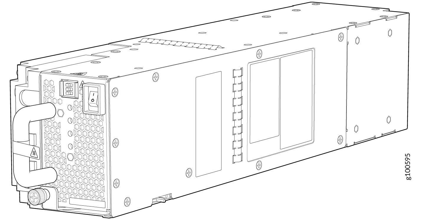
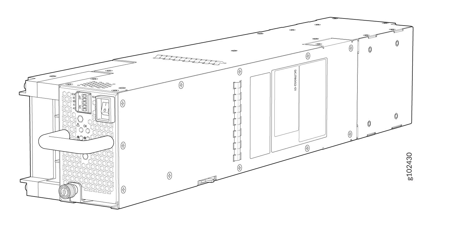
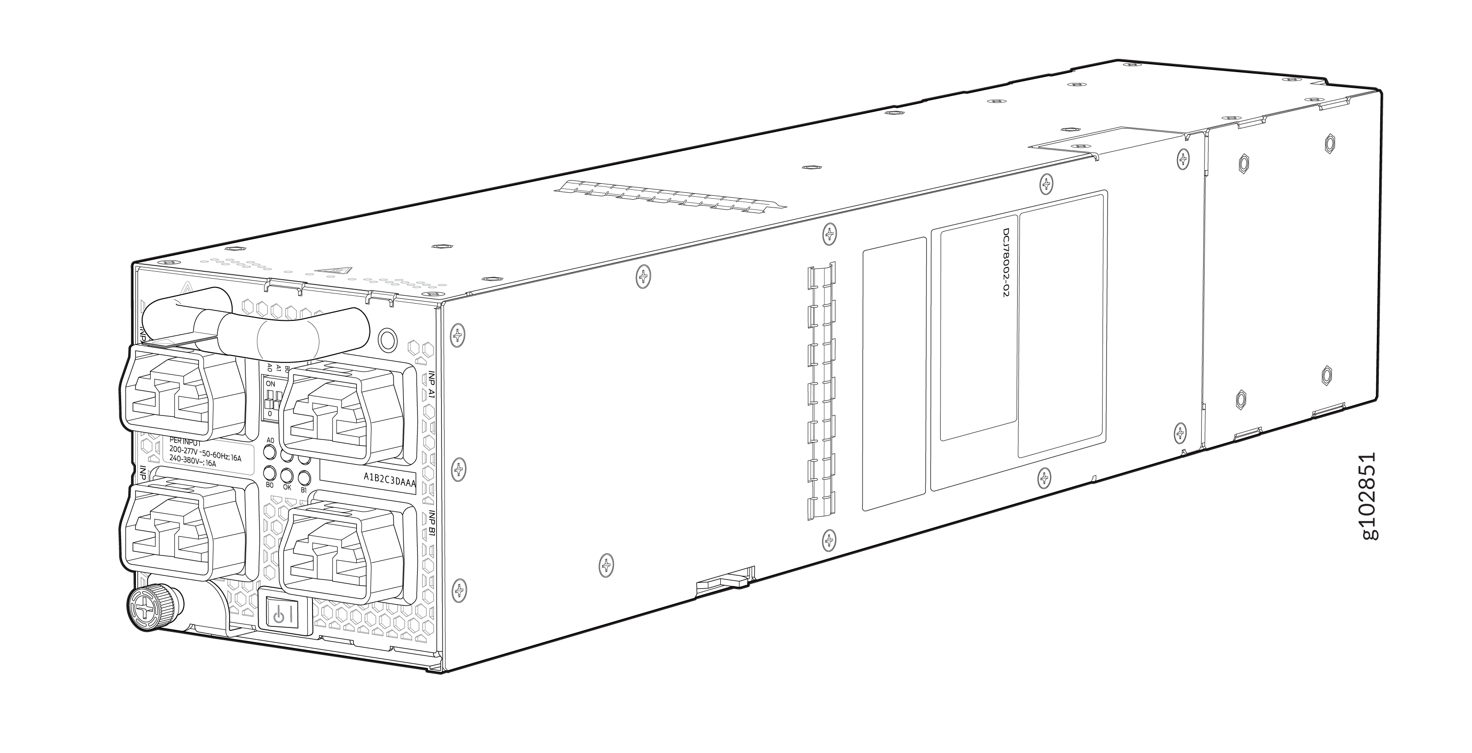
Table 1 provides an overview of the differences among the power supplies.
|
Power Supply Model |
Input Type |
Wattage |
|---|---|---|
|
JNP10K-PWR AC |
AC only |
2700 W |
|
JNP10K-PWR-AC2 |
AC, HVAC, or HVDC |
5000 W, single feed; 5500 W, dual feed |
|
JNP10K-PWR-AC3 |
AC |
|
|
JNP10K-PWR DC |
DC only |
2500 W |
|
JNP10K-PWR-DC2 |
DC only |
2750 W, single feed; 5500 W, dual feed |
|
JNP10K-PWR-DC3 |
DC only |
|
|
JNP10K-PWR-AC3H |
HVAC or HVDC |
|
Software on MX10008
The Juniper Networks MX10008 router runs on Junos OS, which provides Layer 3 routing services. The same Junos OS code base that runs on MX10008 router also runs on all Juniper Networks M Series, MX Series, and T Series routers and SRX Series Firewalls.
See Also
MX10008 Configurations and Upgrade Options
MX10008 Configurations
Table 2 lists the hardware configurations for a MX10008 modular chassis—base (AC and DC versions), redundant (AC and DC versions), and redundant (HVAC, DC, and HVDC)—and the components included in each configuration.
Router Configuration |
Configuration Components |
|---|---|
|
Base AC configuration MX10008-BASE |
|
|
Base AC configuration with JNP10K-PWR-AC2 components MX10008-BASE |
|
|
Base DC configuration MX10008-BASE |
|
|
Base DC configuration with JNP10K-PWR-DC2 or JNP10K-PWR-DC3 components MX10008-BASE |
|
|
Redundant AC configuration MX10008-PREMIUM |
|
|
Redundant AC configuration with JNP10K-PWR-AC2 or JNP10K-PWR-AC3 components MX10008-PREMIUM |
|
|
Redundant DC configuration MX10008-PREMIUM |
|
|
Redundant DC configuration with JNP10K-PWR-DC2, JNP10K-PWR-DC3, or JNP10K-PWR-AC3H (HVDC) components MX10008-PREMIUM |
|
You can install up to eight line cards that support any switch fabric compatible line card in the MX10008.
MX10K-LC9600 Line Card is compatible only with JNP10008-SF2 and operates only if JNP10008-FAN2 fan tray and JNP10K-PWR-AC2 or JNP10K-PWR-DC2 power supplies are installed.
Line cards and the cable management system are not part of the base or redundant configurations. You must order them separately.
If you want to purchase additional power supplies (AC, DC, HVAC, or HVDC), SFBs, or RCBs for your router configuration, you must order them separately.
Upgrade Kits
Most of the MX10008 hardware configurations can be upgraded to newer MX10008 router hardware using an upgrade kit. Upgrading requires JNP10008-FAN2 and JNP10008-FTC2 cooling system, and 5550 W power supplies. Depending on whether you already have the newer cooling system and power supplies will determine your upgrade kit. You can use to find the right upgrade kit.
Original Configuration |
Upgrading to Configuration |
Current Power and Cooling |
Order Power Supply Upgrade Kit |
|---|---|---|---|
MX10008-BASE |
PTX10008-BASE3 |
JNP10K-PWR-AC and JNP10008-FAN |
PTX10008-AC-UPGKIT and PTX10008-B3-UPGKIT |
JNP10K-PWR-AC2 and JNP10008-FAN2 |
PTX10008-B3-UPGKIT |
||
JNP10K-PWR-DC and JNP10008-FAN |
PTX10008-DC-UPGKIT and PTX10008-B3-UPGKIT |
||
JNP10K-PWR-DC2 and JNP10008-FAN 2 |
PTX10008-B3-UPGKIT |
||
MX10008-BASE |
PTX10008-PREM2 |
JNP10K-PWR-AC and JNP10008-FAN |
PTX10008-AC-UPGKIT and PTX10008-P2-UPGKIT |
JNP10K-PWR-AC2 and JNP10008-FAN2 |
PTX10008-P2-UPGKIT |
||
JNP10K-PWR-DC and JNP10008-FAN |
PTX10008-DC-UPGKIT and PTX10008-P2-UPGKIT |
||
JNP10K-PWR-DC2 and JNP10008-FAN 2 |
PTX10008-P2-UPGKIT |
||
MX10008-BASE |
PTX10008-PREM3 |
JNP10K-PWR-AC and JNP10008-FAN |
PTX10008-AC-UPGKIT and PTX10008-P3-UPGKIT |
JNP10K-PWR-AC2 and JNP10008-FAN2 |
PTX10008-P2-UPGKIT |
||
JNP10K-PWR-DC and JNP10008-FAN |
PTX10008-DC-UPGKIT and PTX10008-P3-UPGKIT |
||
JNP10K-PWR-DC2 and JNP10008-FAN 2 |
PTX10008-P3-UPGKIT |
||
MX10008-PREMIUM |
PTX10008-BASE3 |
JNP10K-PWR-AC and JNP10008-FAN |
PTX10008-AC-UPGKIT and PTX10008-B3-UPGKIT |
JNP10K-PWR-AC2 and JNP10008-FAN2 |
PTX10008-B3-UPGKIT |
||
JNP10K-PWR-DC and JNP10008-FAN |
PTX10008-DC-UPGKIT and PTX10008-B3-UPGKIT |
||
JNP10K-PWR-DC2 and JNP10008-FAN 2 |
PTX10008-B3-UPGKIT |
||
MX10008-PREMIUM |
PTX10008-PREM2 |
JNP10K-PWR-AC and JNP10008-FAN |
PTX10008-AC-UPGKIT and PTX10008-P2-UPGKIT |
JNP10K-PWR-AC2 and JNP10008-FAN2 |
PTX10008-P2-UPGKIT |
||
JNP10K-PWR-DC and JNP10008-FAN |
PTX10008-DC-UPGKIT and PTX10008-P2-UPGKIT |
||
JNP10K-PWR-DC2 and JNP10008-FAN 2 |
PTX10008-P2-UPGKIT |
||
MX10008-PREMIUM |
PTX10008-PREM3 |
JNP10K-PWR-AC and JNP10008-FAN |
PTX10008-AC-UPGKIT and PTX10008-P3-UPGKIT |
JNP10K-PWR-AC2 and JNP10008-FAN2 |
PTX10008-P3-UPGKIT |
||
JNP10K-PWR-DC and JNP10008-FAN |
PTX10008-DC-UPGKIT and PTX10008-P3-UPGKIT |
||
JNP10K-PWR-DC2 and JNP10008-FAN 2 |
PTX10008-P3-UPGKIT |
You can install up to eight line cards that support any switch fabric compatible line card in the MX10008 router.
Line cards and the cable management system are not part of the base or redundant configurations. You must order them separately.
MX10008 Components and Configurations
Table 4 lists the four hardware configurations for an MX10008 modular chassis—base (AC and DC versions), and redundant (AC and DC versions)—and the components included in each configuration.
Router Configuration |
Configuration Components |
|---|---|
|
Base AC configuration MX10008-BASE |
|
|
Base DC configuration MX10008-BASE |
|
|
Redundant AC configuration MX10008-PREMIUM |
|
|
Redundant DC configuration MX10008-PREMIUM |
|
|
AC or DC configuration MX10008-PREMIUM |
|
You can install up to eight line cards in the router.
MX10K-LC9600 Line Card is compatible only with JNP10008-SF2 and operates only if JNP10008-FAN2 fan tray and JNP10K-PWR-AC2 or JNP10K-PWR-DC2 power supplies are installed.
Line cards and the cable management system are not part of the base or redundant configurations. You must order them separately.
If you want to purchase additional power supplies (AC, DC, HVAC, or HVDC), SFBs, or RCBs for your router configuration, you must order them separately.
MX10008 Component Redundancy
The MX10008 router is designed so that no single point of failure can cause the entire system to fail. The following major hardware components in the redundant configuration provide redundancy:
Routing and Control Board (RCB)—The RCB consolidates the Routing Engine function with the control plane function in a single unit. The MX10008 router can have one RCB in a base configuration or two RCBs in a redundant configuration. When two RCBs are installed, one functions as the primary and the other functions as the backup. If the primary RCB (or either of its components) fails, the backup can take over as the primary RCB. See MX10008 Routing and Control Board Description.
Switch Fabric Boards (SFBs)—The MX10008 router has six SFB slots. Five SFBs are required for base operation and the sixth SFB provides n+1 redundancy. All six SFBs are active and can sustain full throughput rate. The fabric plane can tolerate one SFB failure without any loss of performance. See MX10008 Switch Fabric Board Description.
Power supplies—The MX10008 router requires three power supplies for minimum operation. Additional power supplies, provide n+1 redundancy for the system. AC, DC, HVAC, and HVDC systems tolerate a single power supply to fail without system interruption. If one power supply fails in a fully redundant system, the other power supplies can provide full power to the MX10008 router indefinitely.
The MX10008 router also supports source redundancy. Two sets of lugs are provided for the JNP10K-PWR-AC cables, four sets of lugs are provided for the JNP10K-PWR-DC2 cables, and two AC power cords are provided for each JNP10K-PWR-AC2 power supply.
Cooling system—The fan trays have redundant fans, which are controlled by the fan tray controller. If one of the fans fails, the host subsystem increases the speed of the remaining fans to provide sufficient cooling for the router indefinitely. See MX10008 Cooling System and Airflow.
MX10008 Hardware and CLI Terminology Mapping
This topic describes the hardware terms used in MX10008 router documentation and the corresponding terms used in the Junos OS command-line interface (CLI). See Table 5.
Hardware Item (CLI) |
Description (CLI) |
Value (CLI) |
Item In Documentation |
Additional Information |
|---|---|---|---|---|
Chassis |
JNP10008 [MX10008] |
– |
Router chassis |
|
Routing and Control Board |
CB (n) |
n is a value in the range of 0–1. Multiple line items appear in the CLI if more than one RCB is installed in the chassis. |
||
FPC (n) |
Abbreviated name of the Flexible PIC Concentrator (FPC) On MX10008, an FPC equates to a line card. |
n is a value in the range of 0–7. The value corresponds to the line card slot number in which the line card is installed. |
Line card (The router does not have actual FPCs—the line cards are the FPC equivalents on the router.) |
|
Xcvr (n) |
Abbreviated name of the transceiver |
n is a value equivalent to the number of the port in which the transceiver is installed. |
Optical transceivers |
|
PSU (n) |
One of the following:
|
n is a value in the range of 0–5. The value corresponds to the power supply slot number. |
AC, DC, HVAC, or HVDC power supply |
One of the following: |
Fan tray |
JNP10008-FAN or JNP10008-FAN2 |
– |
Fan tray |
|
SFB (n) |
This field indicates:
|
n is a value in the range of 0–5. |
Fabric plane |
show chassis fabric sfb |