ON THIS PAGE
MX10008 Power Planning
MX10008 power specifications and requirements are described in the following topics. Use the information to calculate the power consumption for the MX10008 and plan your configuration’s power requirements.
Power Requirements for MX10008 Components
Table 1 lists the power requirements for different hardware components of an MX10008 router under typical voltage conditions and optics.
|
Component |
Description |
Power Requirements (Watts) |
||
|---|---|---|---|---|
|
At 77° F (25° C) |
At 104° F (40° C) |
At 131° F (55° C) |
||
|
JNP10008-SF |
MX10008 SFB |
235 W |
235 W |
235 W |
|
JNP10008-SF2 |
MX10008 SFB |
400 W |
400 W |
400 W |
|
JNP10008-FAN |
MX10008 fan tray |
475 W |
475 W |
475 W |
|
JNP10008-FAN2 |
MX10008 fan tray |
1207 W |
1207 W |
1207 W |
|
JNP10008-FAN3 |
MX10008 fan tray |
1620 W |
1620 W |
1620 W |
|
JNP10K-RE1 or JNP10K-RE1-128 |
MX10008 RCB |
100 W |
175 W |
175 W |
| JNP10K-RE3, JNP10K-RE3-LT, JNP10K-RE3-256, or JNP10K-RE3LT256 | MX10008 RCB |
120 W |
178 W |
178 W |
|
MX10K-LC2101 line card |
Line-rate throughput of up to 2.4 Tbps. |
1335 W |
1425 W |
- |
|
MX10K-LC480 line card |
Line-rate throughput of up to 480 Gbps. |
430 W (10G) 370 W (1G) |
450 W (10G) 390 W (1G) |
480 W (10G) 420 W (1G) |
|
MX10K-LC9600 line card |
Line-rate throughput of up to 9.6 Tbps. |
1655 W |
1770 W |
- |
|
MX10K-LC4800 line card |
Line-rate throughput of up to 4.8 Tbps. |
966 W |
1005 W |
1030 W |
|
MX10K-LC4802 line card |
Line-rate throughput of up to 4.8 Tbps. |
1082 W |
1099 W |
1133 W |
Calculate Power Requirements for an MX10008 Router
Use the information in this topic to calculate power requirements of your MX10008 configuration and the number of power supplies required for different MX10008 router configurations.
The calculations in this topic represent the maximum power requirements that you need to budget for your MX10008 router configuration. The actual power consumption of your router will be less than the calculated results shown here and will vary based on the hardware and software configuration of your router, the amount of traffic passing through the line cards, and environmental variables such as room temperature.
Before you begin these calculations:
Ensure you understand the different router configurations. See MX10008 Components and Configurations.
Ensure that you know the power requirements of different router components. See Table 2.
This topic describes these tasks:
- Calculating the Power Consumption of Your MX10008 Configuration
- Calculating the Number of Power Supplies Required for Your MX10008 Configuration
Calculating the Power Consumption of Your MX10008 Configuration
Use the following procedure to determine the maximum power you need to supply to the router. To calculate maximum system power consumption, you first determine the combined maximum internal power requirements of all the router components and then divide this result by the power supply output power.
To calculate maximum system power consumption:
Calculating the Number of Power Supplies Required for Your MX10008 Configuration
Use this procedure to calculate the number of power supplies required by your router configuration. The minimum power configuration for MX10008 routers is three power supplies.
To calculate the number of power supplies required for your minimum router configuration:
We recommend that you maintain six power supplies in your router at all times. Replace failed power supplies immediately to prevent unexpected failures.
If a new line card is installed in an operational router, power management does not power on the line card if the increased power demand exceeds the total available power, including redundant power. If redundant power is used to power on the line card, a minor alarm is raised, which becomes a major alarm in five minutes if the condition is not corrected.
JNP10K-PWR-AC Power Specifications
MX10008 redundant configuration router can use either AC or DC power supplies; base configuration routers are AC only.
Table 6 lists the power specifications for the AC power supply (JNP10K-PWR-AC) used in an MX10008 chassis.
Item |
Specifications |
|---|---|
AC input voltage |
Operating range: 200–240 VAC |
AC input line frequency |
50–60 Hz |
AC input current rating |
16 A |
AC output power |
2700 W |
Table 7 shows the physical specifications for an AC power supply.
Specification |
Value |
|---|---|
Height |
3.5 in. (8.89 cm) |
Width |
3.6 in. (9.14 cm) |
Depth |
14.4 in. (36.58 cm) |
Weight |
6.8 lb (3.08 kg) |
See Also
JNP10K-PWR-AC2 Power Specifications
MX10008 redundant configuration router can use either AC or DC power supplies; base configuration routers are AC only. The JNP10K-PWR-AC2 power supply supports AC, HVAC, and HVDC.
Table 8 lists the power specifications for the AC power supply (JNP10K-PWR-AC) used in an MX10008 chassis.
|
Item |
Specifications |
|---|---|
|
AC input voltage |
180–305 VAC |
|
DC input voltage |
190–410 VDC |
|
Input current rating |
28.5 A |
|
DC output power |
12.3 V, 5500 W with dual feed and 5000 W with single feed |
Table 9 shows the physical specifications for a JNP10K-PWR-AC2 power supply.
|
Specification |
Value |
|---|---|
|
Height |
3.5 in. (8.89 cm) |
|
Width |
3.6 in. (9.14 cm) |
|
Depth |
15.1 in. (38.35 cm) |
|
Weight |
11.4 lb (5.17 kg) |
For more information, see:
JNP10K-PWR-AC3 Power Specifications
The JNP10K-PWR-AC3 power supply supports AC.
Table 10 lists the power specifications for the AC power supply (JNP10K-PWR-AC3) used in a PTX10004 chassis.
|
Specification |
Value |
|---|---|
|
AC input voltage |
180–264 VAC |
|
Input current rating |
16 A |
|
DC output power |
12.3 V |
Table 11 shows the physical specifications for a JNP10K-PWR-AC3 power supply.
|
Specification |
Value |
|---|---|
|
Height |
3.386 in. (8.60 cm) |
|
Width |
3.584 in. (9.10 cm) |
|
Depth |
17.15 (43.57 cm) |
|
Weight |
12.8 lbs (5.8 kg) |
JNP10K-PWR-AC3H Power Specifications
The JNP10K-PWR-AC3H power supply supports HVAC and HVDC.
Table 12 lists the power specifications for the HVAC and HVDC power supply (JNP10K-PWR-AC3H) used in a MX10008 chassis.
|
Specification |
Value |
|---|---|
|
AC input voltage |
180–305 VAC (each feed) HVAC 190 – 410 VAC (each feed) HVDC |
|
Input current rating |
50 A |
|
DC output power |
12.3 V (HVAC) 12.9 V (HVDC) |
Table 13 shows the physical specifications for a JNP10K-PWR-AC3H power supply.
|
Specification |
Value |
|---|---|
|
Height |
3.386 in. (8.60 cm) |
|
Width |
3.584 in. (9.10 cm) |
|
Depth |
16.966 in (43.10 cm) |
|
Weight |
12.8 lbs (5.8 kg) |
MX10008 Power Cables Specifications
Each AC power supply has two independent 16 A rated AC inlets on the faceplate. Most sites distribute power through a main conduit that leads to frame-mounted power distribution panels, one of which can be located at the top of the rack that houses the router. An AC power cord connects each power supply to the power distribution panel.
Each detachable AC power cord is 8 feet (approximately 2.5 meters) long. The appliance couple end of the cord inserts into the AC appliance inlet on the faceplate of the AC power supply. The coupler type is C19 as described by the International Electrotechnical Commission (IEC) standard 60320. The plug end of the power cord fits into the power source outlet that is standard for your geographical location.
MX10008 AC, high-voltage alternating current (HVAC), and high-voltage direct current (HVDC) power supplies have specific cord requirements. Use the following sections to determine the cable requirements based on the model of your power supply and any mode settings:
JNP10K-PWR-AC see JNP10K-PWR-AC Power Cable Specifications
JNP10K-PWR-AC2 with 20-A input, see JNP10K-PWR-AC2 Power Cable Specifications
JNP10K-PWR-AC2 with 30-A input, see JNP10K-PWR-AC2 Power Cable Specifications for 30-A Input
- JNP10K-PWR-AC Power Cable Specifications
- JNP10K-PWR-AC2 Power Cable Specifications
- JNP10K-PWR-AC2 Power Cable Specifications for 30-A Input
JNP10K-PWR-AC Power Cable Specifications
Table 14 lists the AC power cord specifications for MX10008 routers for various countries and regions.
Country/Region |
Electrical Specifications |
Plug Standards |
Juniper Model Number |
Graphic |
|---|---|---|---|---|
Argentina |
250 VAC, 16 A, 50 Hz |
IRAM Type RA/3/20 |
CBL-EX-PWR-C19-AR |
 |
Australia |
250 VAC, 15 A, 50 Hz |
AS/NZS 3112 Type SAA/3/15 |
CBL-EX-PWR-C19-AU |
 |
Brazil |
250 VAC, 16 A, 50 Hz |
NBR 14136: 2002 Type BR/3/20 |
CBL-EX-PWR-C19-BR |
 |
China |
250 VAC, 16 A, 50 Hz |
GB 1002 Type PRC/3/16 |
CBL-EX-PWR-C19-CH |
 |
Europe (except Italy, Switzerland, and United Kingdom) |
250 VAC, 16 A, 50 Hz |
CEE (7) VII Type VIIG |
CBL-EX-PWR-C19-EU |
 |
Israel |
250 AC, 16 A, 50 Hz |
SI 32/1971 Type IL/3 |
SI 32/1971 Type IL/3 |
 |
Italy |
250 VAC, 16 A, 50 Hz |
CEI 23-16 Type I/3/16 |
CBL-EX-PWR-C19-IT |
 |
Japan |
250 VAC, 16 A, 60 Hz |
NEMA 6–20 Type N6/20 |
CBL-EX-PWR-C19-JP (default) |
 |
250 VAC, 16 A, 50 Hz or 60 Hz |
NEMA L6–20P Type NEMA Locking |
CBL-EX-PWR-C19-JPL |
 |
|
Korea |
250 VAC, 16 A, 50 Hz |
CEE (7) VII Type VIIG |
CBL-EX-PWR-C19-KR |
|
North America |
250 VAC, 16 A, 60 Hz |
NEMA 6–20 Type N6/20 |
CBL-EX-PWR-C19-US (default) |
|
250 VAC, 16 A, 50 Hz or 60 Hz |
NEMA L6–20P Type NEMA Locking |
CBL-EX-PWR-C19-USL |
|
|
South Africa |
250 VAC, 16 A, 50 Hz |
SABS 164/1:1992 Type ZA/3 |
CBL-EX-PWR-C19-SA |
 |
Switzerland |
250 VAC, 16 A, 50 Hz |
SEV 5934/2 Type 23G |
CBL-EX-PWR-C19-SZ |
 |
United Kingdom |
250 VAC, 13 A, 50 Hz |
BS 1363/A Type BS89/13 |
CBL-EX-PWR-C19-UK |
 |
Worldwide (other) |
250 VAC, 16 A, 50 Hz |
EN 60320-2-2/1 |
CBL-EX-PWR-C19-C20 |
 |
AC power cords for MX10008 routers are intended for use with these routers only. Do not use the cord for another product.
Power Cable Warning (Japanese) |
|---|
Warning:
The attached power cable is only for this product. Do not use the cable for another product.  |
Power cords must not block access to router components. We recommend that you route all AC power cord cables through the power cord tray provided with the router.
The router is installed in a restricted-access location. It has a separate protective earthing terminal on the chassis that must be permanently connected to earth ground to adequately ground the chassis and protect the operator from electrical hazards.
JNP10K-PWR-AC2 Power Cable Specifications
The JNP10K-PWR-AC2 power supply operates in two modes:
-
30-A input with 5500 W output
JNP10K-PWR-AC2 Power Cable Specifications for 30-A Input shows cables and connectors for 30-A input.
-
20-A input with 3000 W output
Table 15 shows cables appropriate for 20-A input.
Do not run JNP10K-PWR-AC2 power supplies using 20-A cables if connected to 30-A input.
|
Locale |
Cord Set Rating |
Plug Standards |
Spare Juniper Model Number |
Graphic |
|---|---|---|---|---|
|
Argentina |
16 A, 250 VAC |
IRAM 2073 Type RA/3 |
CBL-JNP-SG4-AR |
|
|
Australia and New Zealand |
15 A, 250 VAC |
AS/NZS 3112 |
CBL-JNP-SG4-AU |
|
|
Brazil |
16 A, 250 VAC |
NBR 14136 Type BR/3 |
CBL-JNP-SG4-BR |
|
|
China |
16 A, 250 VAC |
GB2099 |
CBL-JNP-SG4-CH |
|
|
Europe (except Italy, Switzerland, and United Kingdom) |
20 A, 250 VAC |
CEE 7/7 |
CBL-JNP-SG4-EU |

|
|
Great Britain |
13 A, 250 VAC, |
BS1363 |
CBL-JNP-SG4-UK |
|
|
India |
16 A, 250 VAC |
SANS 164/1 |
CBL-JNP-SG4-SA |
|
|
Israel |
16 A, RA, 250 VAC |
SI 32/1971 Type IL/3G |
CBL-JNP-SG4-IL |
|
|
Italy |
16 A, 250 VAC |
CEI 23-16 |
CBL-JNP-SG4-IT |
|
|
North America |
20 A, 250 VAC |
3-5958P4 to IEC 60320 C20 |
CBL-JNP-SG4-C20 |
|
|
16 A, 250 VAC |
Locking NEMA L6-20P |
CBL-JNP-SG4-US-L |
|
|
|
NEMA 6-20P |
CBL-JNP-SG4-US |
|
||
|
South Africa |
16 A, 250 VAC |
SANS 164/1 |
CBL-JNP-SG4-SA |
|
|
Switzerland |
16 A, 250 VAC |
CEI 23-50 |
CBL-JNP-SG4-SZ |
|
| Locale | Cord Set Rating | Plug Standard | Spare Juniper Model Number | Graphic |
|---|---|---|---|---|
| North America | 16 A, 277 V | NEMA L7-20P | CBL-JNP-SG4-HVAC |
|
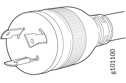
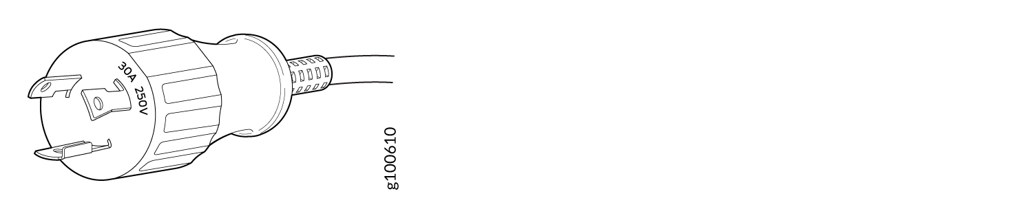
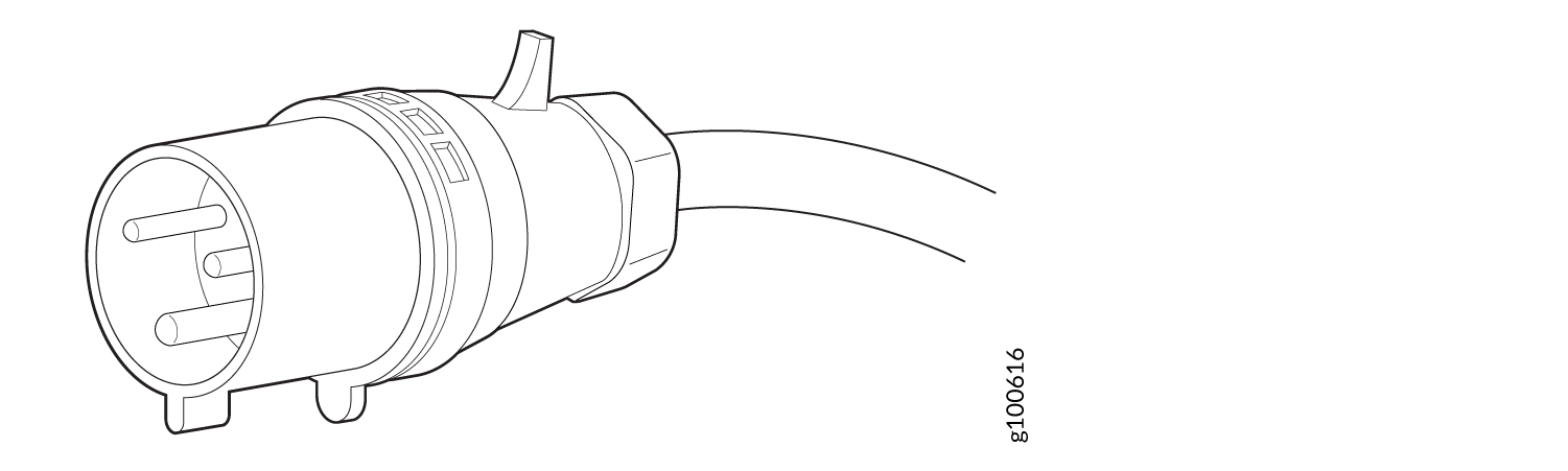
JNP10K-PWR-AC2 Power Cable Specifications for 30-A Input
The JNP10K-PWR-AC2 HVAC or HVDC power supplies requires a high voltage cable assembly when set for 30-A input. One end of the cable has an Anderson APP-400 connector, the other end of the cable is bare wire. See Figure 1 and Table 17. These cables are separately orderable and are not shipped automatically with JNP10K-PWR-AC2 orders. An example of the right-angle cable and connector is shown in Figure 3.
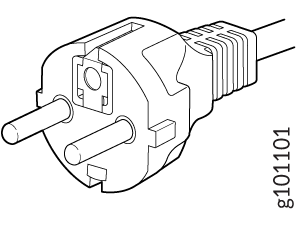
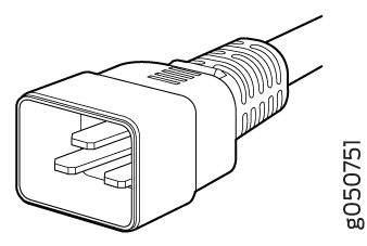
For connection to AC systems, Juniper provides a cable with either a NEMA 30-A connector (Figure 1) or an IEC 330P6W connector (Figure 2).
Locale |
Cord Set Rating |
Plug Standards |
Connector |
Spare Juniper Model Number |
|
|---|---|---|---|---|---|
HVDC power cord |
Any |
30- A, 400 VAC |
UL 950 and IEC 60950 |
Anderson/straight to bare wire |
CBL-PWR2-BARE |
30-A, 400 VAC |
UL 950 and IEC 60950 |
Anderson/right-angle to bare wire |
CBL-PWR2-BARE-RA |
||
AC power cord |
Continental Europe |
30-A 250 VAC |
UL 950 and IEC332P6 |
Anderson/right-angle to IEC 332P6 |
CBL-PWR2-332P6W-RA |
30-A 250 VAC |
UL 950 and IEC332P6 |
Anderson/straight to IEC332P6 |
CBL-PWR2-332P6W |
||
North America |
30-A 240 VAC |
IEC330P6 |
Anderson/right-angle to IEC 330P6 |
CBL-PWR2-330P6W-RA |
|
30-A 240 VAC |
IEC330P6 |
Anderson/straight to IEC 330P6 |
CBL-PWR2-330P6W |
||
30-A 250 VAC |
UL 498, CSA |
Anderson/right-angle to L6-30P |
CBL-PWR2-L6-30P-RA |
||
30-A 250 VAC |
UL 498, IEC5958P4 |
Anderson/straight to L6-30P |
CBL-PWR2-L6-30P |
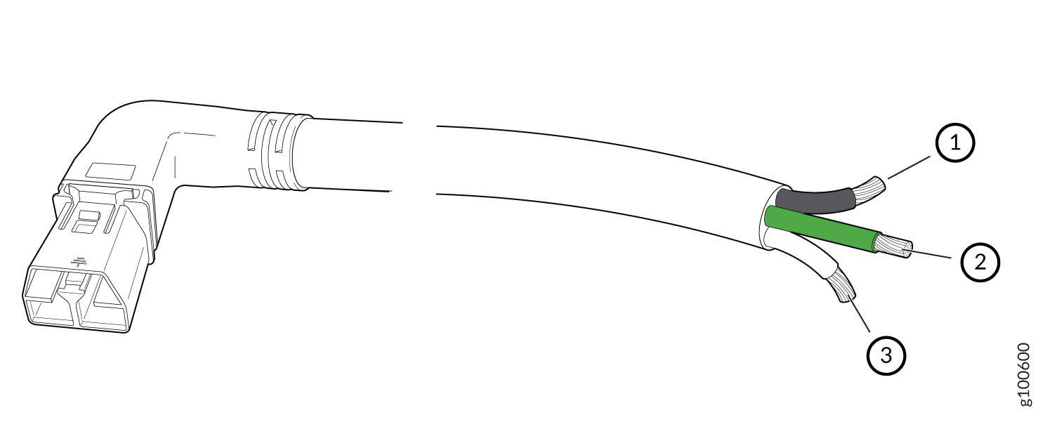
1 — Black wire–Return (+) | 3 — White wire–Neutral |
2 — Green wire-Ground |
JNP10K-PWR-AC3 Power Cable Specifications
The JNP10K-PWR-AC3 power supply operates in two modes:
-
20-A input with 7800 W or 6000 W or 3000 W output
-
15-A input with 7800 W or 6900 W, or 4600 W, or 2300 W output
When power cords with right angle plugs at the PSU end are selected, they must be in pairs of Right Angle Left Plugs for inputs A0 or B0 and Extended Right Angle Left Plugs for inputs A1 or B1.
See Table 18 for a list of appropriate cables.
Do not run JNP10K-PWR-AC3 power supplies using 16-A or 20-A cables if connected to 15-A input.
You can prevent AC power cables from being exposed to hot air exhaust by always routing the power cables away from the fan trays and power supplies.
With right angle power cords and the baffle installed, the power cords will be exposed to hot exhaust air. The IEC C21 plugs have a temperature rating of 155C and the power cord cables have a rating of 90C.
|
Locale |
Cord Set Rating |
Plug Standard |
Spare Juniper Model Number |
Graphic |
|---|---|---|---|---|
| Straight Plug at PSU Input | ||||
|
Australia and New Zealand |
15 A, 250 VAC | AS/NZS 3112 |
CBL-PWRC21-AU |

|
|
Europe (except Italy, Switzerland, and United Kingdom) |
16A, 250 VAC | CEE 7/7 |
CBL-PWRC21-EU |
 |
|
Italy |
16A, 250 VAC | CEI 23-16 |
CBL-PWRC21-IT |

|
|
North America |
20A, 250 VAC |
Locking NEMA L6-20P |
CBL-PWRC21-US-L |

|
| NEMA 6-20P |
CBL-PWRC21-US |

|
||
| International | 16A, 250VAC |
IEC-309 316P6W |
CBL-PWRC21-316P6 |
|
| North America | 20A, 250 VAC |
IEC-309 320P6W |
CBL-PWRC21-320P6 |
|
| Japan | 20A, 250 VAC | NEMA L6-20P |
CBL-PWRC21-JP-L |
|
| China | 16A, 250 VAC | GB2099-1 |
CBL-PWRC21-CN |

|
| North America | 20A, 250 VAC | IEC-320-C20 |
CBL-PWRC21-C20-NA |
|
| Europe | 16A, 250 VAC | IEC-320-C20 |
CBL-PWRC21-C20-EU |
|
| Japan | 20A, 250 VAC | IEC-320-C20 |
CBL-PWRC21-C20-JP |
|
| China | 16A, 250 VAC | IEC-320-C20 |
CBL-PWRC21-C20-CN |
|
| Switzerland | 16A, 250 VAC | SEV1011 |
CBL-PWRC21-SZ |
|
| South Africa | 16A, 250 VAC |
RA SANs 164/1 |
CBL-PWRC21-SA |

|
| India | 16A, 250VAC | RA IS 1293 |
CBL-PWRC21-IN |
|
| United Kingdom | 16A, 250 VAC | BS 1363 |
CBL-PWRC21-UK |
 |
| Israel | 16A, 250 VAC |
SI 32/1971 Type IL/3G |
CBL-PWRC21-IL |

|
| Brazil | 16A, 250 VAC |
NBR 14136 Type BR/3 |
CBL-PWRC21-BR |

|
| Argentina | 16A, 250 VAC |
IRAM 2073 Type RA/3 |
CBL-PWRC21-AR |

|
| Right Angle Left Plug at PSU Input | ||||
| USA | 20A, 250 VAC | NEMA L6-20P | CBL-PWRC21R-US-L |
|
| USA | 20A, 250 VAC | NEMA 6-20P | CBL-PWRC21R-US |
|
| Europe | 16A, 250 VAC | CEE 7/7 | CBL-PWRC21R-EU |
|
| Australia | 15A, 250 VAC | AS/NZ 3112 | CBL-PWRC21R-AU |
|
| Italy | 16A, 250 VAC | CEI 23-50 | CBL-PWRC21R-IT |
|
| International | 16A, 250 VAC |
IEC 60309 316P6W |
CBL-PWRC21R-316P6 | |
| North America | 16A, 250VAC |
IEC 60309 320P6W |
CBL-PWRC21R-320P6 | |
| Japan | 20A, 250 VAC | NEMA L6-20P | CBL-PWRC21R-JP-L |
|
| China | 16A, 250 VAC | GB2099-1 | CBL-PWRC21R-CN |
|
| North America | 16A, 250 VAC |
IEC-60320 C20 |
CBL-PWRC21R-C20-NA |
|
| Europe | 16A, 250 VAC |
IEC 60320 C20 |
CBL-PWRC21R-C20-EU |
|
| Japan | 20A, 250 VAC |
IEC 60320 C20 |
CBL-PWRC21R-C20-JP |
|
| China | 16A, 250 VAC |
IEC 60320 C20 |
CBL-PWRC21R-C20-CN |
|
| Switzerland | 16A, 250 VAC | SEV 1011 | CBL-PWRC21R-SZ | |
| South Africa | 16A, 250 VAC | SANS 164/1 | CBL-PWRC21R-SA |
|
| India | 16A, 250 VAC | IS 1293, RA | CBL-PWRC21R-IN |
|
| United Kingdom | 16A, 250 VAC | BS1363 | CBL-PWRC21R-UK | |
| Israel | 16A, 250 VAC |
SI 32/1971 TYPE IL/3G |
CBL-PWRC21R-IL |
|
| Brazil | 16A, 250 VAC |
NBR 14136 TYP BR/3 |
CBL-PWRC21R-BR |
|
| Argentina | 16A, 250 VAC |
IRAM 2073 TYPE RA/3 |
CBL-PWRC21R-AR |
|
| Extended Right Angle Left Plug at PSU Input | ||||
| USA | 20A, 250 VAC | NEMA L6-20P | CBL-PWRC21RL-US-L |
|
| USA | 20 A, 250 VAC | NEMA 6-20P | CBL-PWRC21RL-US |
|
| Europe | 16A, 250 VAC | CEE 7/7 | CBL-PWRC21RL-EU |
|
| Australia | 15A, 250 VAC | AS/NZ 3112 | CBL-PWRC21RL-AU |
|
| Italy | 16A, 250 VAC | CEI 23-50 | CBL-PWRC21RL-IT |
|
| International | 16A, 250 VAC |
IEC-60309 316P6W |
CBL-PWRC21RL-316P6 | |
| North America | 20A, 250 VAC |
IEC-60309 320P6W |
CBL-PWRC21RL-320P6 | |
| Japan | 20A, 250 VAC | NEMA L6-20P | CBL-PWRC21RL-JP-L |
|
| China | 16A, 250 VAC | GB2099-1 | CBL-PWRC21RL-CN |
|
| North America | 20A, 250 VAC |
IEC-60320 C20 |
CBL-PWRC21RL-C20NA |
|
| Europe | 16A, 250 VAC |
IEC-60320 C20 |
CBL-PWRC21RL-C20EU |
|
| Japan | 20A, 250 VAC |
ICE-60320 C20 |
CBL-PWRC21RL-C20JP |
|
| China | 16A, 250 VAC |
IEC-60320 C20 |
CBL-PWRC21RL-C20CN |
|
| Switzerland | 16A, 250 VAC | SEV 1011 | CBL-PWRC21RL-SZ | |
| South Africa | 16A, 250 VAC | SANS 164/1 | CBL-PWRC21RL-SA |
|
| India | 16A, 250 VAC | IS1293, RA | CBL-PWRC21RL-IN |
|
| United Kingdom | 16A, 250 VAC | BS 1363 | CBL-PWRC21RL-UK | |
| Israel | 16A, 250 VAC |
SI 32/1971 Type IL/3G |
CBL-PWRC21RL-IL |
|
| Brazil | 16A, 250 VAC |
NBR 14136 Type BR/3 |
CBL-PWRC21RL-BR |
|
| Argentina | 16A, 250 VAC |
IRAM 2073 Type RA/3 |
CBL-PWRC21RL-AR |
|
JNP10K-PWR-DC Power Specifications
The DC power supply (JNP10K-PWR-DC) is supported in only the MX10008 redundant configuration. Table 19 lists the power specifications for the JNP10K-PWR-DC power supply used in an MX10008 chassis.
Item |
Specifications |
|---|---|
DC input voltage |
|
DC input current rating |
60 A maximum at nominal operating voltage (–48 VDC) for each input terminal |
Output power |
2500 W |
Table 20 shows the physical specifications for a JNP10K-PWR-DC power supply.
Specification |
Value |
|---|---|
Height |
3.5 in. (8.89 cm) |
Width |
3.6 in. (9.14 cm) |
Depth |
14.4 in. (36.58 cm) |
Weight |
6 lb (2.72 kg) |
See Also
JNP10K-PWR-DC2 Power Specifications
JNP10K-PWR-DC2 power supplies are supported in only the MX10008 redundant configuration. Table 21 lists the power specifications for the HVDC power supply used in a MX10008 chassis.
|
Item |
Specifications |
|---|---|
|
DC input voltage |
|
|
DC input current rating |
|
|
Output power |
2200 W for low input (60-A) single feed 4400 W for low input (60-A) dual feed 2750 W for high input (80-A) single feed 5500 W for high input (80-A) dual feed |
Table 22 shows the physical specifications for a JNP10K-PWR-DC2 power supply.
|
Specification |
Value |
|---|---|
|
Height |
3.5 in. (8.89 cm) |
|
Width |
3.6 in. (9.14 cm) |
|
Depth |
16.05 in. (40.77 cm) |
|
Weight |
8.1 lbs (3.67 kg) |
For more information, see:
JNP10K-PWR-DC3 Power Specifications
Table 23 lists the power specifications for the DC power supply (JNP10K-PWR-DC3) used in MX10008 routers.
|
Item |
Specifications |
|---|---|
|
DC input voltage |
|
|
Input current rating |
60 A/80 A |
|
Output power |
12.3 VDC |
Table 24 shows the physical specifications for a JNP10K-PWR-DC3 power supply.
|
Specification |
Value |
|---|---|
|
Height |
3.386 in. (8.60 cm) |
|
Width |
3.584 in. (9.10 cm) |
|
Depth |
15.391 in. (39.09 cm) |
|
Weight |
12.8 lb. (5.7 kg) |
For more information, see:
MX10008 Grounding Cable and Lug Specifications
You must install the switch in a restricted-access location and ensure it is adequately grounded at all times. Proper grounding ensures your switch is operating correctly and that it meets safety and electromagnetic interference (EMI) requirements. An MX10008 router, has a 2-hole protective grounding terminal on the rear of the chassis beneath the power supplies for grounding.
For AC powered systems, you must also use the grounding wire in the AC power cord along with the 2-hole lug ground connection. This tested system meets or exceeds all applicable EMC regulatory requirements with the 2-hole protective grounding terminal.
To comply with GR-1089 requirements, all intra-building copper cabling used for SFP+, QSFP+, and QSFP28 ports must be shielded and grounded at both ends.
Before router installation begins, a licensed electrician must attach a cable lug to the grounding cables that you supply. See Connect the MX10008 to Earth Ground. A cable with an incorrectly attached lug can damage the router.
Before connecting the router to earth ground, review the following information:
Two threaded inserts (PEM nuts) are provided on the lower rear of the chassis for connecting the router to earth ground. The grounding points are spaced at 0.63 in. (16 mm) centers.
The grounding lug required is a Panduit LCD6-10A-L or equivalent (provided). The grounding lug accommodates 6 AWG (13.3 mm²) stranded wire. If one or more JNP10K-PWR-DC2 power supplies are installed in the chassis and set for high input (80-A), use the Panduit LCD4-14A-L or equivalent (provided). This lug accommodates 4 AWG (21.1mm²) stranded wire.
The grounding cable that you provide for an MX10008 must be the same size or heavier than the input wire of each power supply. Minimum recommendations are 6 AWG (13.3 mm²) stranded copper wire, Class B; 90° C wire, or as permitted by local code.