ON THIS PAGE
Removing and Installing MX10000 Power System Components
MX10008 and MX10016 routers support both AC and DC power supplies. Additionally, MX10000 routers support high-voltage alternating current (HVAC) or high-voltage direct current (HVDC) power supplies. To install and remove the power supplies in a MX10008 router or a MX10016 router, refer to the following sections.
How to Remove a JNP10K-PWR-AC Power Supply
Before you remove an JNP10K-PWR-AC power supply from the chassis:
Ensure you understand how to prevent ESD damage. See Prevention of Electrostatic Discharge Damage.
Ensure that you have the following parts and tools available to remove a JNP10K-PWR-AC power supply from an MX10008 router:
Electrostatic discharge (ESD) grounding strap
Phillips (+) screwdriver, number 1
Replacement power supply or a cover panel for the power supply slot
The JNP10K-PWR-AC power supply in an MX10008 router is a hot-removable and hot-insertable field-replaceable unit (FRU). You remove all power supplies from the rear of the chassis.
Before you remove a power supply, ensure that you have power supplies sufficient to power the router left in the chassis. See Calculate Power Requirements for an MX10008 Router.
Do not leave the power supply slot empty for a long time while the router is operational. Either replace the power supply promptly or install a cover panel over the empty slot.
To remove a JNP10K-PWR-AC power supply from an MX10008 router:
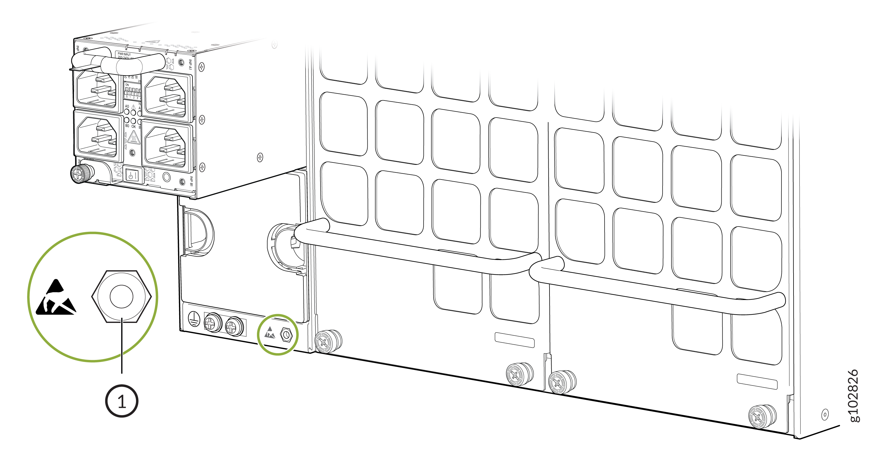
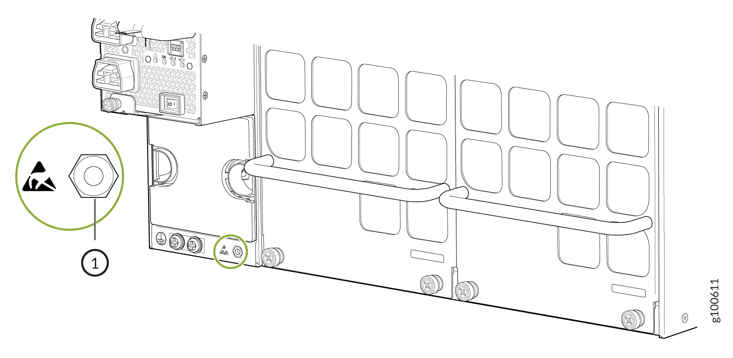
- Attach the electrostatic discharge (ESD) grounding strap
to your bare wrist, and connect the strap to the ESD point on the
chassis. There is an ESD point located next to the protective earthing
terminal and below PSU 5 on the MX10008
rear panel (see Figure 1)
and below PSU_9 on the MX10016 (see Figure 2).Figure 1: ESD Point on the Rear of an MX10008
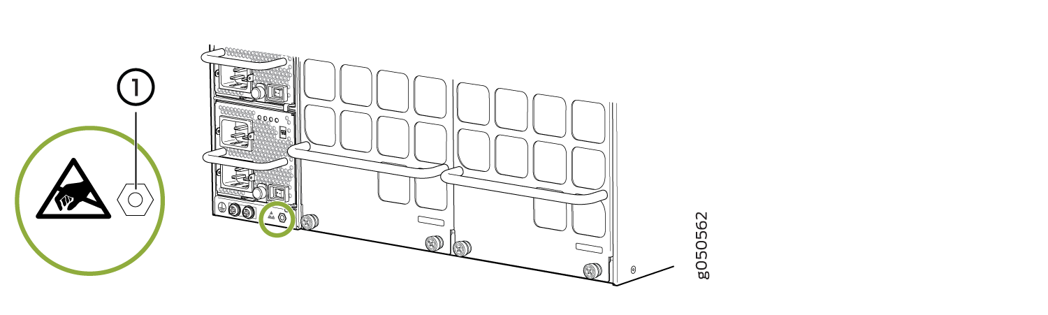 1—
1—ESD point
Figure 2: ESD Point on MX10016 Chassis Rear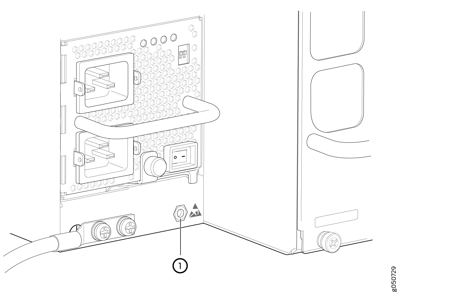 1—
1—ESD point
- Taking care not to touch the power supply output connections,
pins, leads, or solder connections, place one hand under the power
supply to support it. Grasp the power supply handle with your other
hand and pull the power supply completely out of the chassis.CAUTION:
Do not bump the output connections. If the connection hits a solid object, it could damage the power supply.
CAUTION:See the heat symbol
 . The power supply surfaces are hot. Allow a few minutes for the
power supply to cool by pulling the power supply halfway out of the
chassis, or wear protective, heat-resistant gloves while removing
the power supply.
. The power supply surfaces are hot. Allow a few minutes for the
power supply to cool by pulling the power supply halfway out of the
chassis, or wear protective, heat-resistant gloves while removing
the power supply.
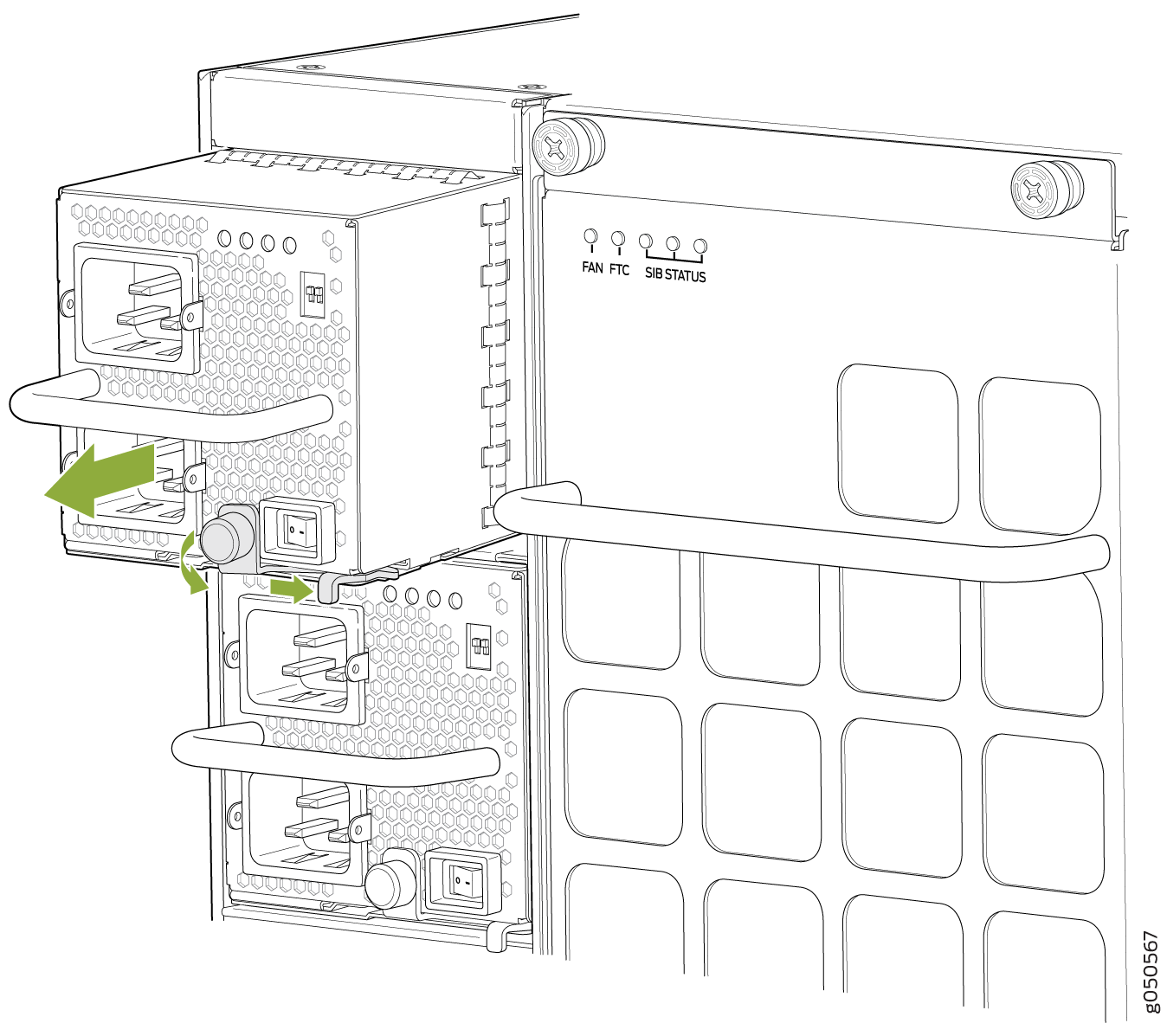
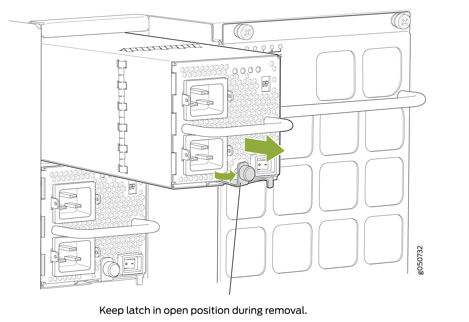
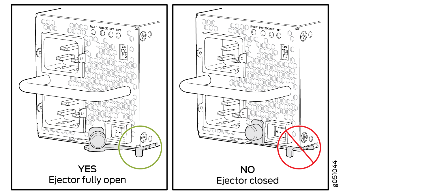
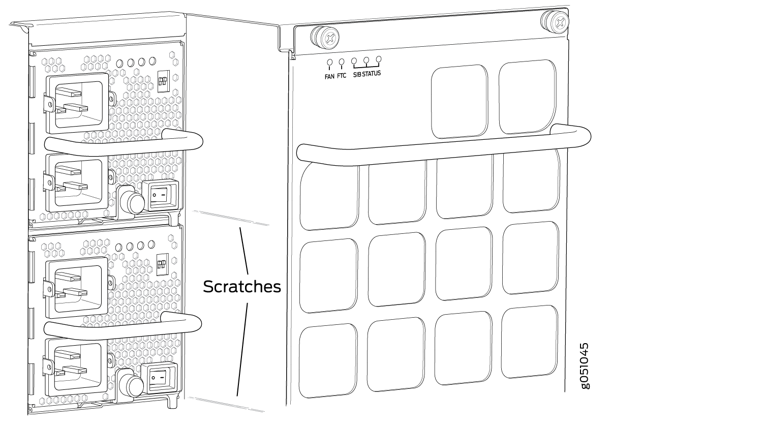
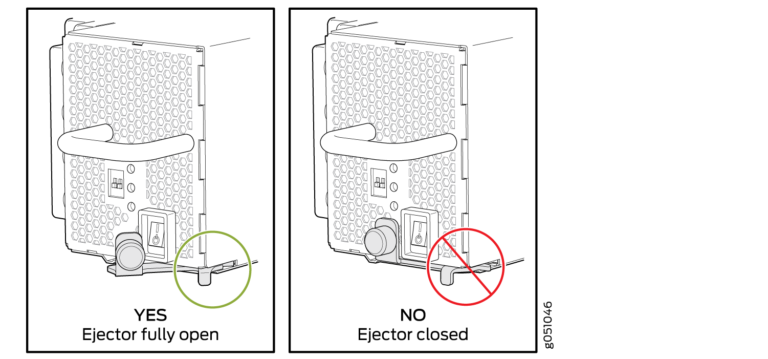
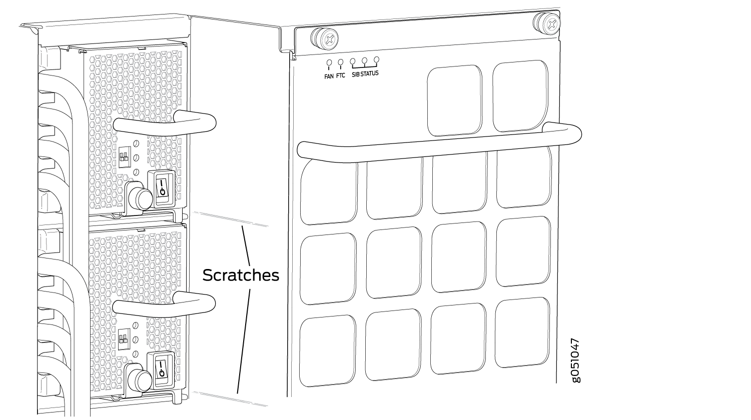
Ensure that the ejector is fully open to avoid scratching the chassis.
 |
 |
See Also
How to Install a JNP10K-PWR-AC Power Supply
Before you install a JNP10K-PWR-AC power supply in the router:
Ensure you understand how to prevent ESD damage. See Prevention of Electrostatic Discharge Damage.
If the AC power source outlets have a power switch, set them to the off (O) position.
Ensure that you have the following parts and tools available to install an AC power supply:
Electrostatic discharge (ESD) grounding strap
Phillips (+) screwdriver, number 1
Power cords appropriate for your geographical location. See MX10008 Power Cables Specifications.
Power cord retainer clips
The JNP10K-PWR-AC power supply in an MX10008 chassis or a MX10016 chassis is a hot-insertable and hot-removable field-replaceanble unit (FRU). You can install up to 6 power supplies in an MX10008 and 10 in a MX10016 router chassis. All power supplies install in the rear of the chassis in the slots provided along the left side.
Do not mix AC and DC power supplies in the same chassis.
See the heat symbol .
Wear heat-resistant hand gloves while accessing the fan tray and
power supply.
To install a JNP10K-PWR-AC power supply in an MX10008 or an MX10016:
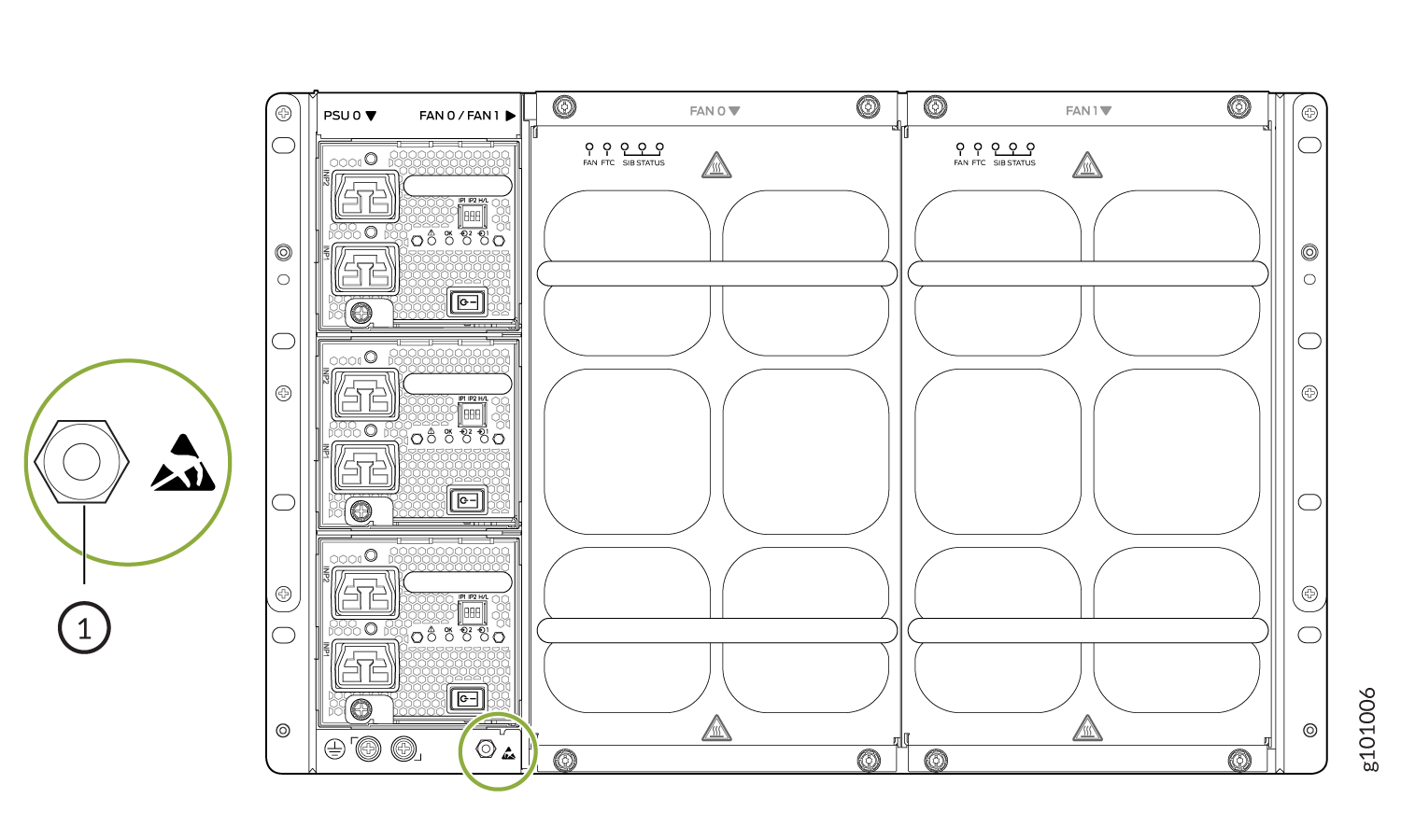
- Attach the electrostatic discharge (ESD) grounding strap
to your bare wrist, and connect the strap to the ESD point on the
chassis. There is an ESD point located next to the protective earthing
terminal and below PSU 5 on the MX10008
rear panel (see Figure 5)
or below PSU_9 on the MX10016 (see Figure 6).Figure 5: ESD Point on the Rear of an MX100081—
ESD point
Figure 6: ESD Point on MX10016 Chassis Rear1—ESD point
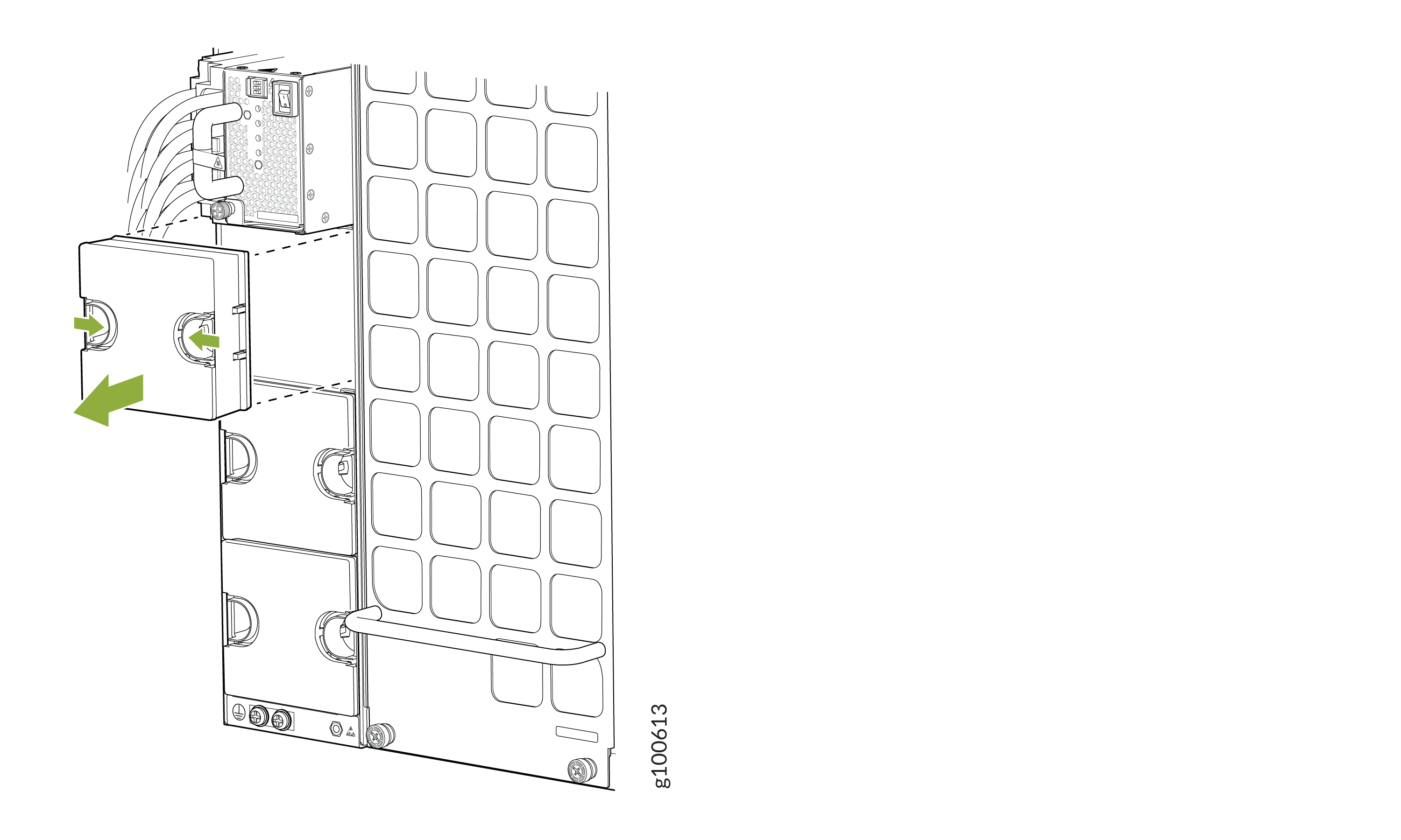
- If the power supply slot has a cover on it, insert your
thumb and forefinger into the finger holes, squeeze and pull the cover
out of the slot. Save the cover for later use. See Figure 7 for removal on an MX10008
and Figure 8 for the MX10016.Figure 7: Removing the Power Supply Cover on an MX10008
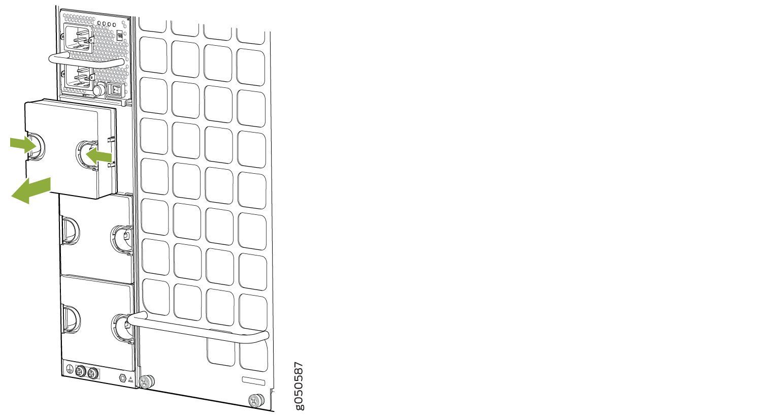 Figure 8: Removing the Power Supply Cover on a MX10016
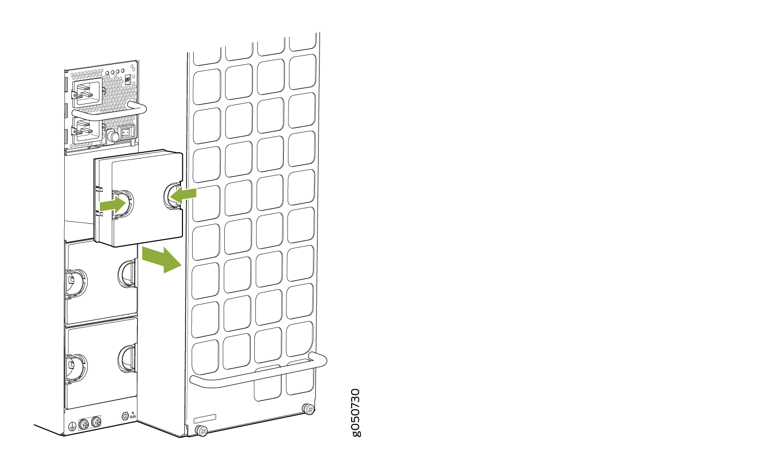
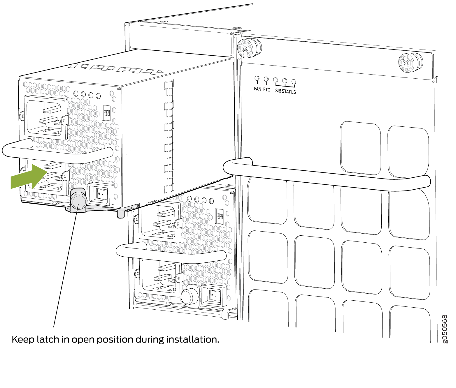
- Tighten the captive screw by turning it clockwise by using
the Phillips (+) screwdriver, number 1. When the screw
is completely tight, the latch locks into the router chassis.Figure 9: Installing a JNP10K-PWR-AC Power Supply in an MX10008
 Note:
Note:Ensure that the ejector is fully open to avoid scratching the chassis.
Figure 10: Installing a JNP10K-PWR-AC Power Supply in an MX10016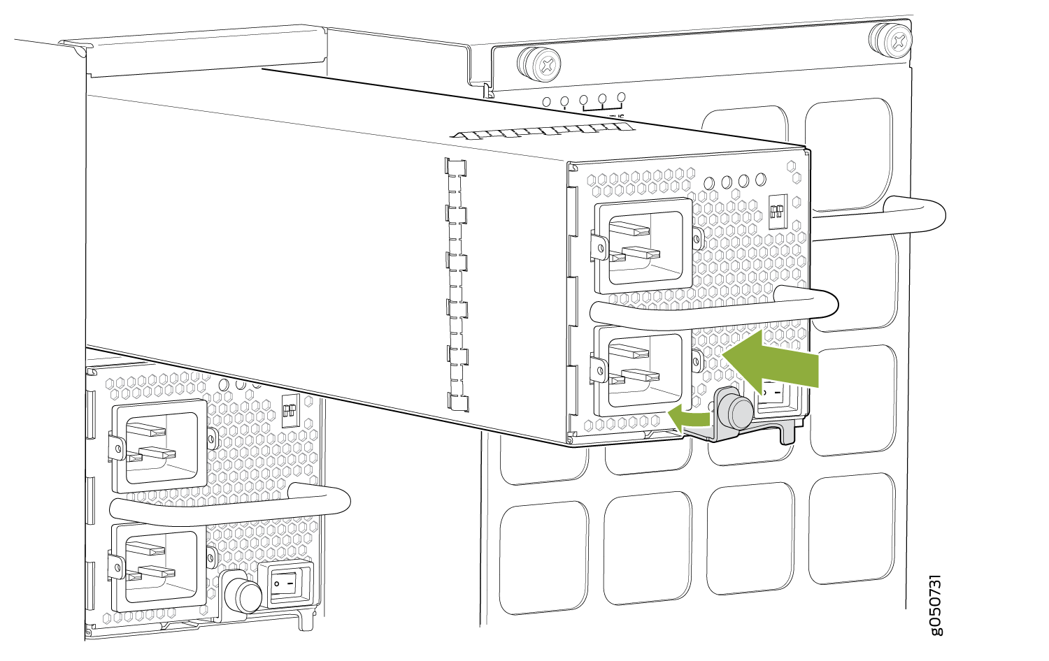
- Manually load balance the power supplies as you attach
each power cable to a dedicated AC power source outlet. To load balance,
route the power cables to alternate between power sources. The JNP10K-PWR-AC
does not share power; all power comes into INP1 (lower receptacle)
and only uses INP2 (top receptacle) at fail over. See Figure 11 for MX10008 and Figure 12Figure 11: Proper Load Balancing for JNP10K-PWR-AC Power Cables on MX10008
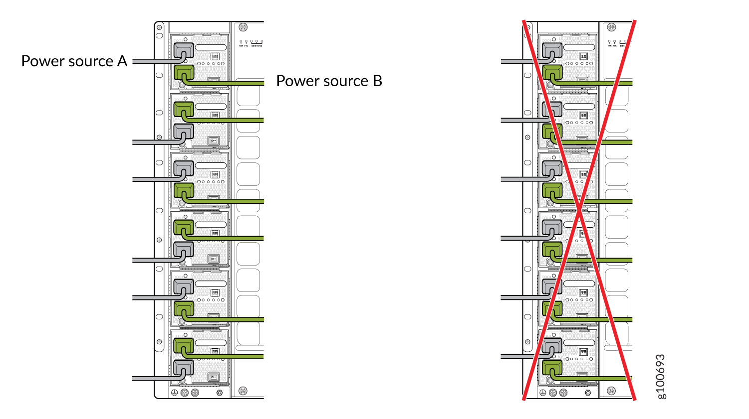 Figure 12: Proper Load Balancing for JNP10K-PWR-AC Power Cables on MX10016
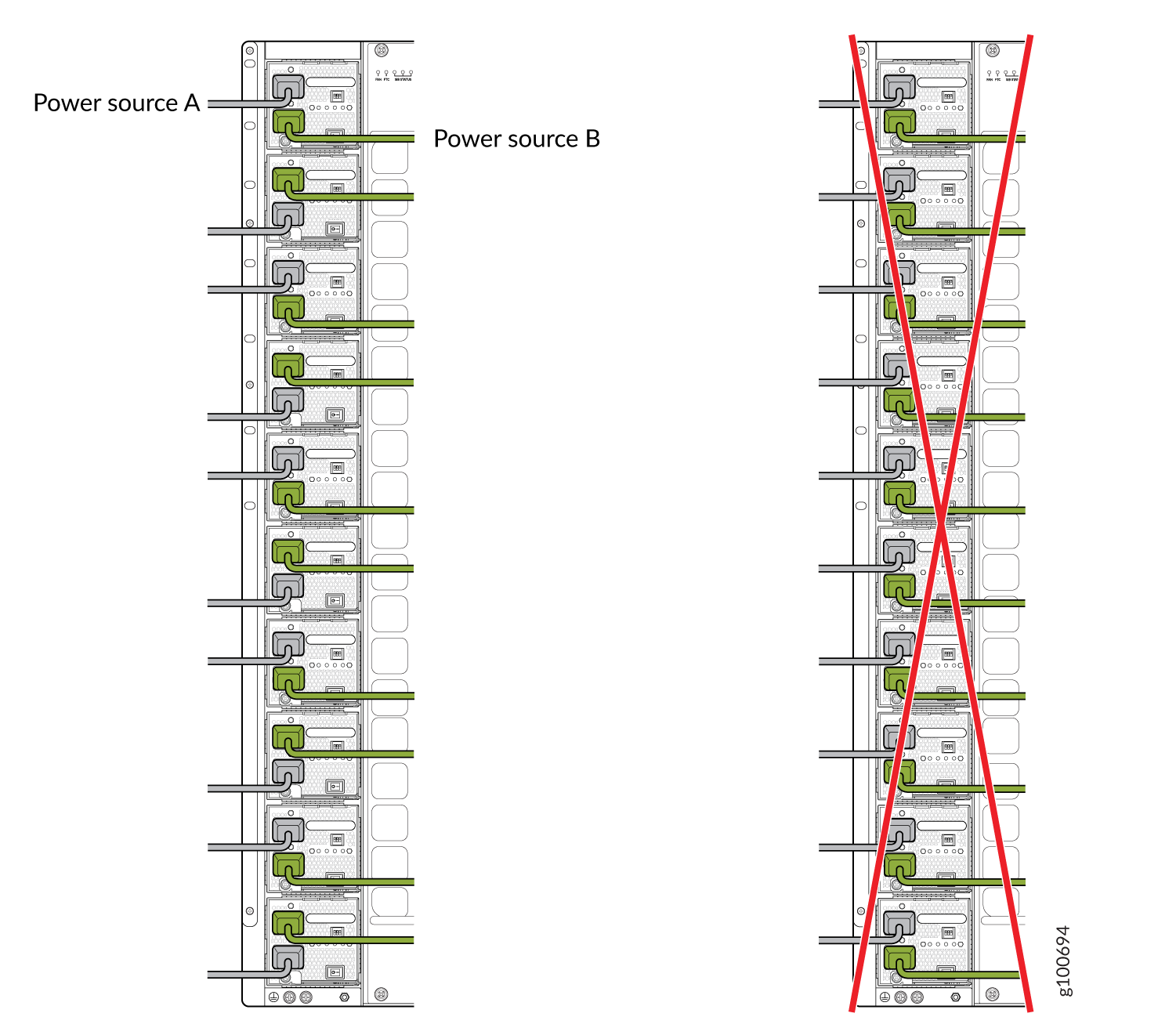 Warning:
Ensure that the power cords do not block access to router components or drape where people can trip on them.
- Fasten the cord retainer by lowering the clip over the
cord and pushing the cord into the adjustment nut of the cord retainer.
Rotate the nut until it is tight against the base of the cord. See Figure 13.Figure 13: Power Cord and Retainer Clip
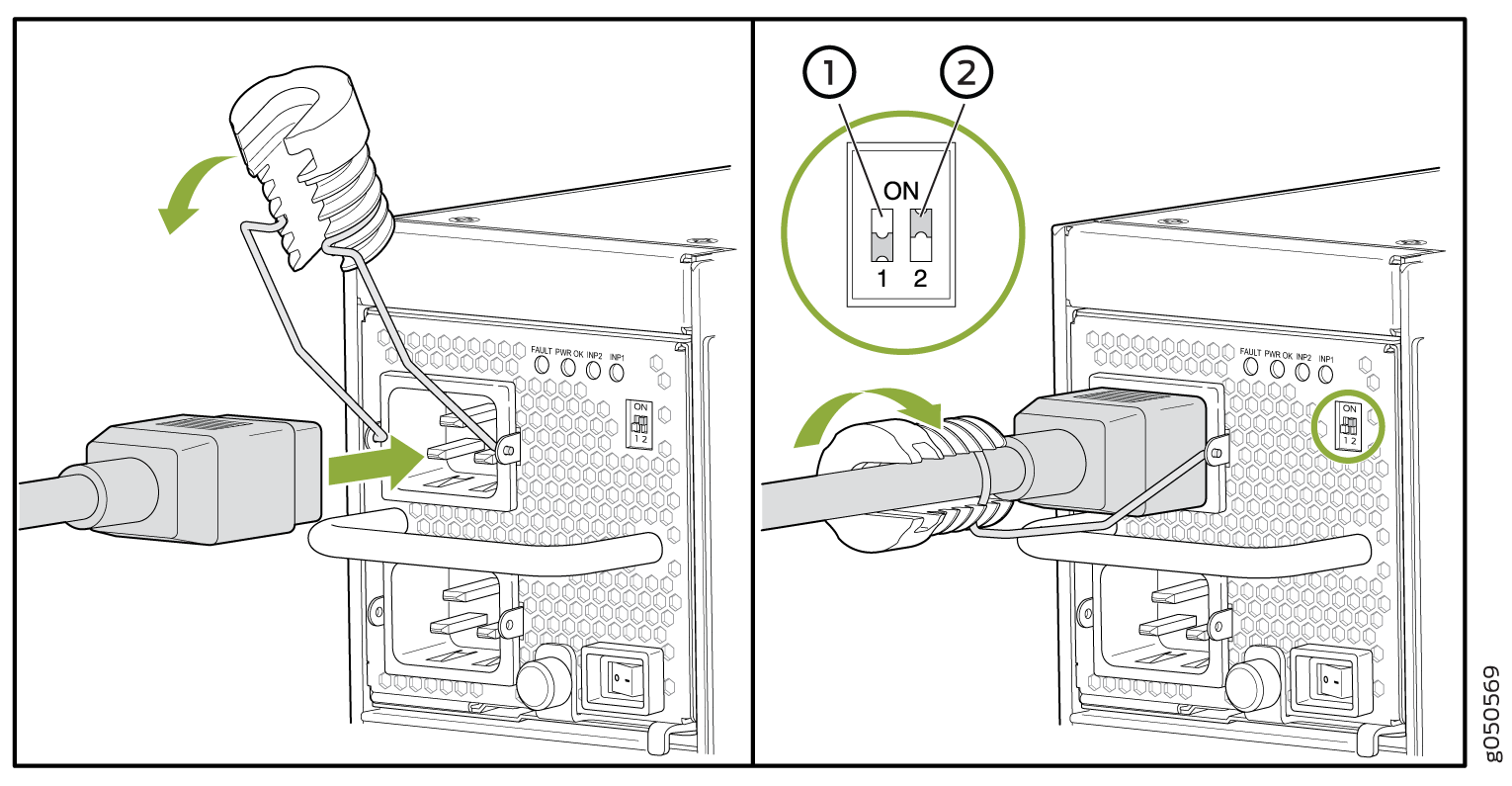 1—
1—Enable switch for INP1 appears as INP0 in output.
2—Enable switch for INP2 appears as INP1 in output.
Warning:Ensure that the power cords do not block access to router components or drape where people can trip on them.
See Also
How to Remove a JNP10K-PWR-AC2 Power Supply
Before you remove an JNP10K-PWR-AC2 power supply from the chassis:
-
Ensure you understand how to prevent ESD damage. See Prevention of Electrostatic Discharge Damage.
Ensure that you have the following parts and tools available to remove a JNP10K-PWR-AC2 power supply from an MX10000 router:
-
Heat protective gloves able to withstand temperatures of 158°F (70°C)
-
Electrostatic discharge (ESD) grounding strap
-
Phillips (+) screwdriver, number 1
-
Replacement power supply or a cover panel for the power supply slot
The JNP10K-PWR-AC2 power supply in an MX10008 or an MX10016 chassis is a hot-removable and hot-insertable field-replaceable unit (FRU). You remove all power supplies from the rear of the chassis.
Protect yourself from severe burns by wearing heat-protective gloves when removing a working JNP10K-PWR-AC2 power supply from the chassis. These power supplies can reach 158°F (70°C ).
Before you remove a power supply, ensure that you have power supplies sufficient to power the router left in the chassis. See Calculate Power Requirements for an MX10008 Router.
Do not leave the power supply slot empty for a long time while the router is operational. Either replace the power supply promptly or install a cover panel over the empty slot.
To remove a JNP10K-PWR-AC2 power supply from an MX10000 router:
-
Attach the electrostatic discharge (ESD) grounding strap to your bare wrist, and
connect the strap to the ESD point on the chassis. There is an ESD point located
next to the protective earthing terminal and below PSU 5 on
the MX10000 rear panel (see Figure 14) and below
PSU_9 on the MX10016 (see Figure 15).
Figure 14: ESD Point on the MX10008 Chassis Rear
 1—
1—ESD point
Figure 15: ESD Point on the MX10016 Chassis Rear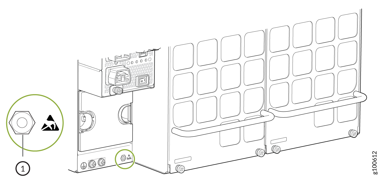 1—
1—ESD point
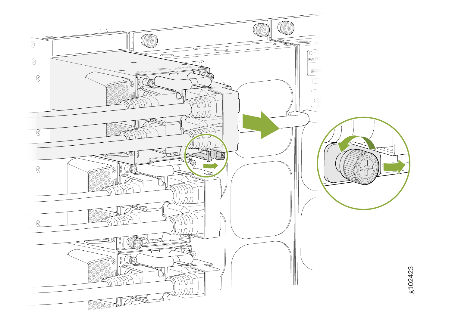
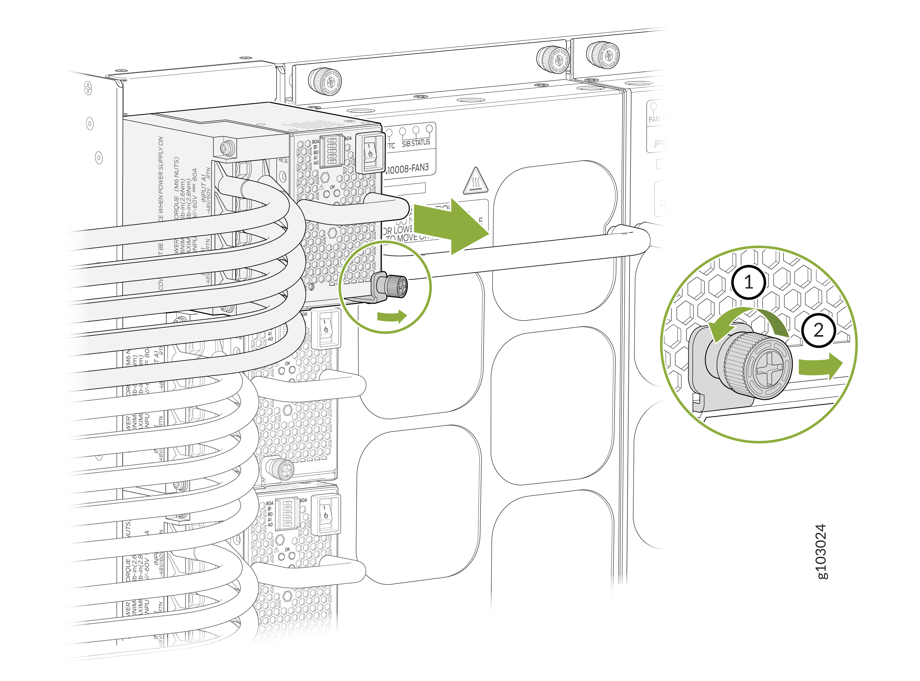
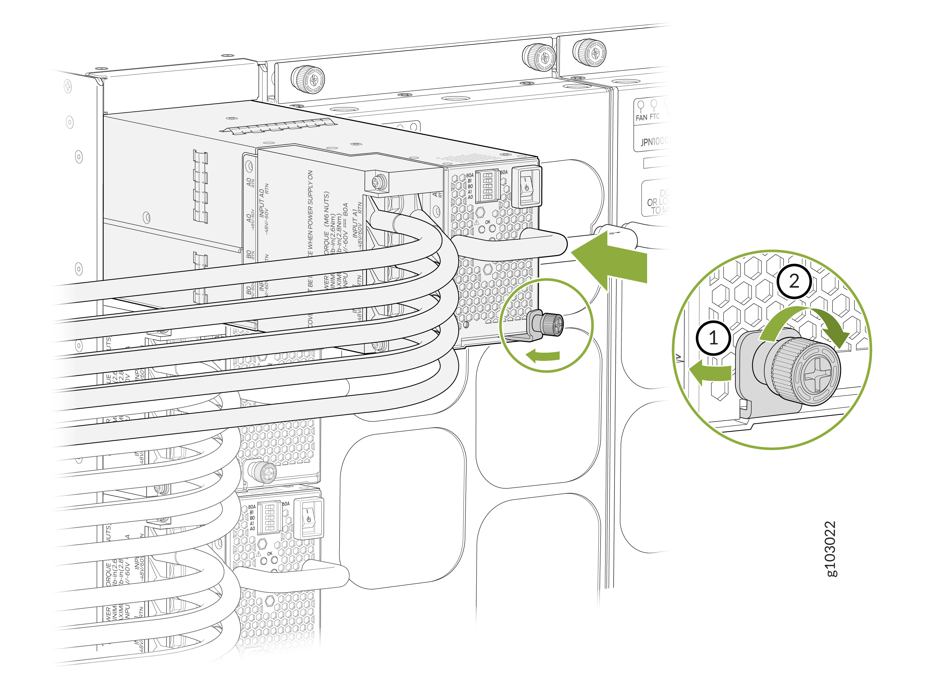
-
Unscrew the captive screw counterclockwise by using the
Phillips (+) screwdriver, number 1. See Figure 16 and Figure 17.
Figure 16: Removing a JNP10K-PWR-AC2 from an MX10008 Chassis
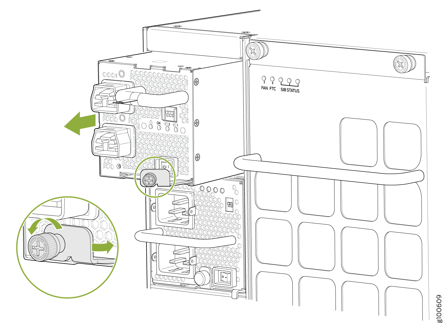 Figure 17: Removing a JNP10K-PWR-AC2 from an MX10016 Chassis
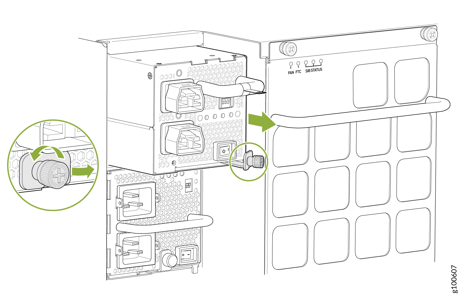
How to Install a JNP10K-PWR-AC2 Power Supply
The JNP10K-PWR-AC2 power supply in an MX10008 or an MX10016 chassis is a hot-insertable and hot-removable field-replaceable unit (FRU). You can install up to 6 AC power supplies in a MX10008 and 10 in a MX10016 router chassis. All power supplies install in the rear of the chassis in the slots provided along the left side.
Do not mix AC and DC power supplies in the same running chassis. You may have both JNP10K-PWR-AC and JNP10K-PWR-AC2 in the same chassis while swapping out one type of power supply for the other.
Protect yourself from severe burns by wearing heat-protective gloves when removing a running JNP10K-PWR-AC2 power supply from the chassis. The power supply can reach 158°F (70°C).
Before you install a JNP10K-PWR-AC2 power supply in the chassis:
Ensure that you have followed all safety warnings and cautions:
-
Ensure you understand how to prevent ESD damage. See Prevention of Electrostatic Discharge Damage.
-
If the AC or DC power source outlets have a power switch, set them to the off (O) position.
Ensure that you have the following parts and tools available to install an JNP10K-PWR-AC2 power supply:
-
Electrostatic discharge (ESD) grounding strap
-
Phillips (+) screwdriver, number 1
-
Power cables appropriate for your geographical location (for low-voltage installations) or input amperage (for high-voltage installations). See MX10008 Power Cables Specifications. HVAC and HVDC connectors and lugs must be installed by a qualified electrician before installation.
To install a JNP10K-PWR-AC2 power supply in an MX10008 or an MX10016:
-
Attach the electrostatic discharge (ESD) grounding strap to your bare wrist, and
connect the strap to the ESD point on the chassis. There is an ESD point located
next to the protective earthing terminal and below PSU5 on
the MX10008 rear panel (see Figure 18) or below
PSU9 on the MX10016 (see Figure 19).
Figure 18: ESD Point on the MX10008 Chassis Rear
1—
ESD point
Figure 19: ESD Point on MX10016 Chassis Rear
1—ESD point
-
If the power supply slot has a cover on it, insert your thumb and forefinger
into the finger holes, squeeze, and pull the cover out of the slot. Save the cover
for later use. See Figure 20 for removal on a
MX10008 and Figure 21
for the MX10016.
Figure 20: Removing the Power Supply Cover on an MX10008
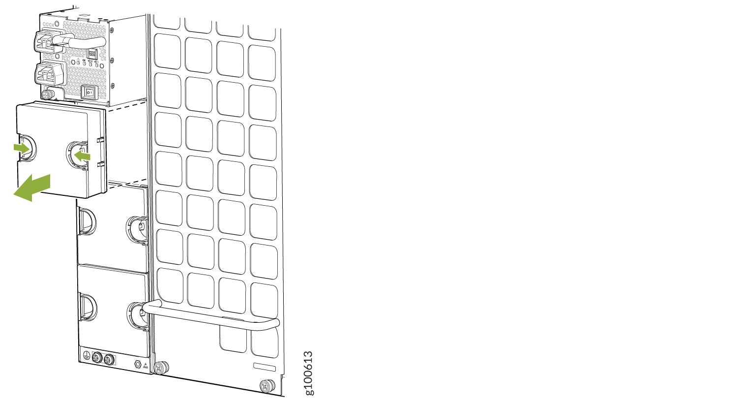 Figure 21: Removing the Power Supply Cover on an MX10016
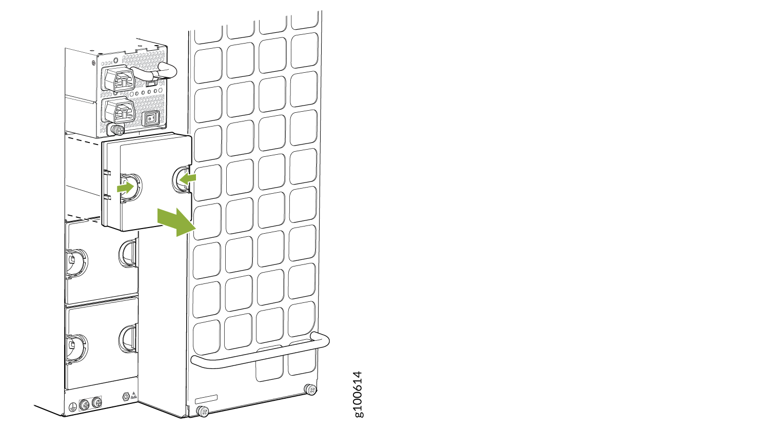
-
Tighten the captive screw by turning it clockwise by using the
Phillips (+) screwdriver, number 1. When the screw is completely tight, the latch
locks into the router chassis.
Figure 22: Installing JNP10K-PWR-AC2 in an MX10008
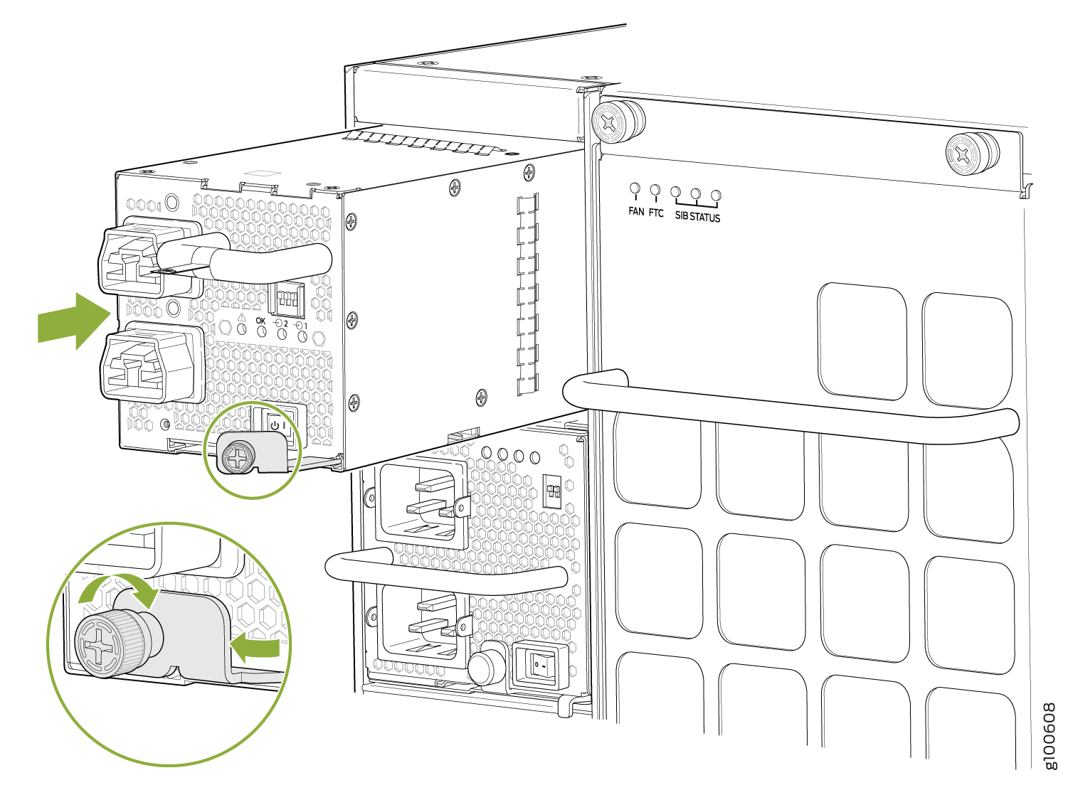 Figure 23: Installing a JNP10K-PWR-AC2 in an MX10016
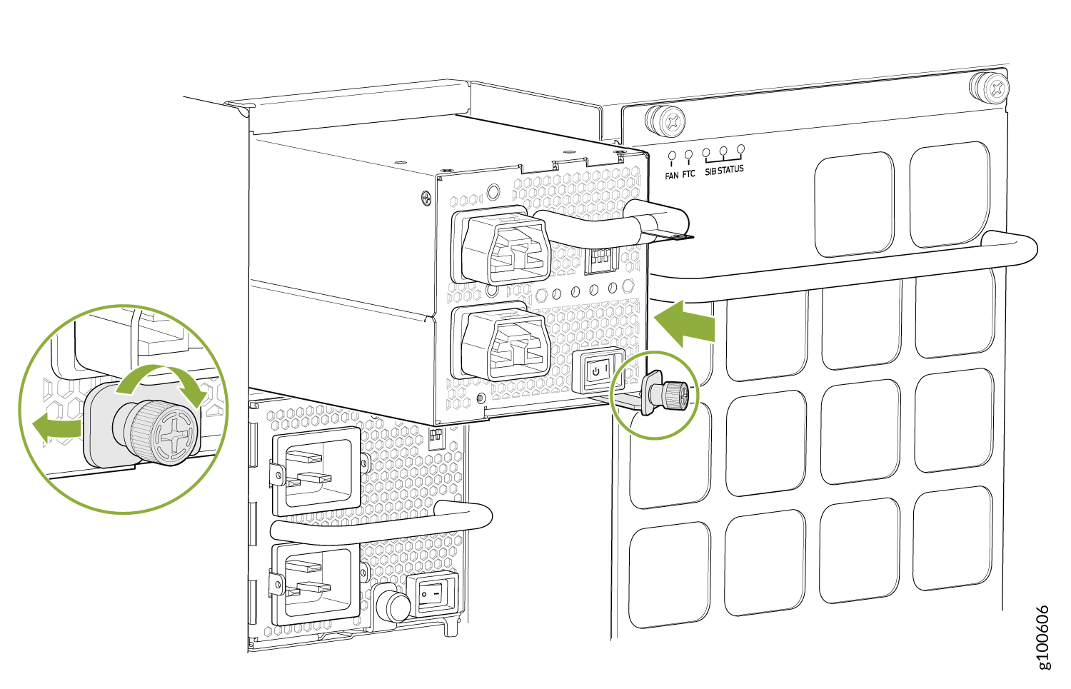
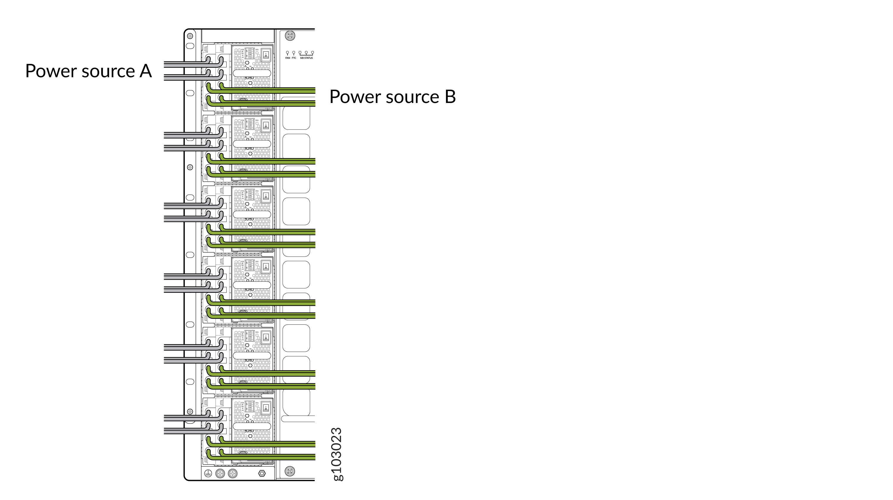
-
Attach each power cable to a dedicated power (A and B). The JNP10K-PWR-AC2 only
requires that each power supply be connected to a separate source. See Figure 24 for some
possible cabling combinations for MX10008 and Figure 25 for
MX10016.
Figure 24: Proper Load Balancing for JNP10K-PWR-AC2 Power Cables on MX10008
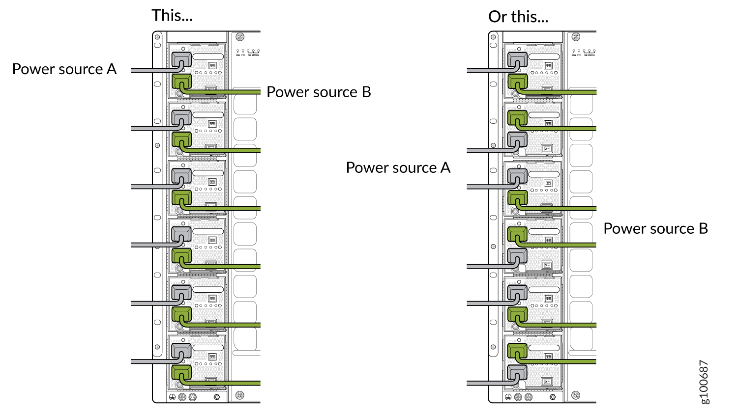 Figure 25: Proper Load Balancing for JNP10K-PWR-AC2 Power Cables on MX100016
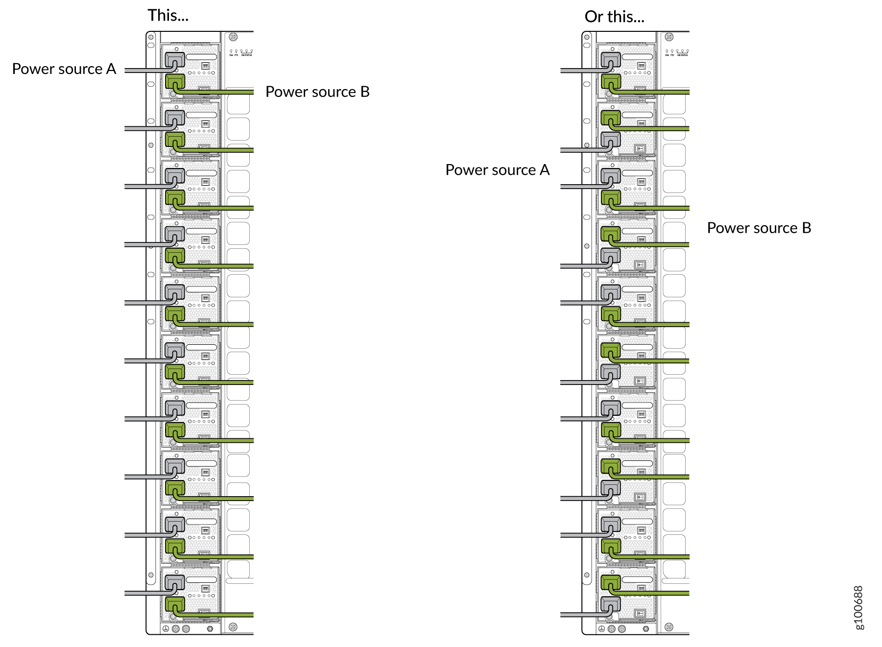
How to Remove a JNP10K-PWR-AC3 Power Supply
Before you remove a JNP10K-PWR-AC3 power supply from the chassis:
-
Ensure that you understand how to prevent ESD damage. See Prevention of Electrostatic Discharge Damage.
-
Ensure that you have the following parts and tools available:
-
Heat-protective gloves able to withstand temperatures of 158°F (70°C)
-
Electrostatic discharge (ESD) grounding strap
-
Phillips (+) screwdriver, number 1
-
Replacement power supply or a cover for the power supply slot
-
Protect yourself from severe burns by wearing heat-protective gloves when removing a working JNP10K-PWR-AC3 power supply from the chassis. These power supplies can reach temperatures between 158 °F and 176 °F (70 °C to 80 °C) when equipment is on.
Before you remove a power supply, ensure that you have power supplies sufficient to power the router left in the chassis. See MX10008 Power Planning.
Do not leave the power supply slot empty for a long time while the router is operational. Either replace the power supply promptly or install a ABPM or a cover over the empty slot.
To remove a JNP10K-PWR-AC3 power supply from a MX10008 router:
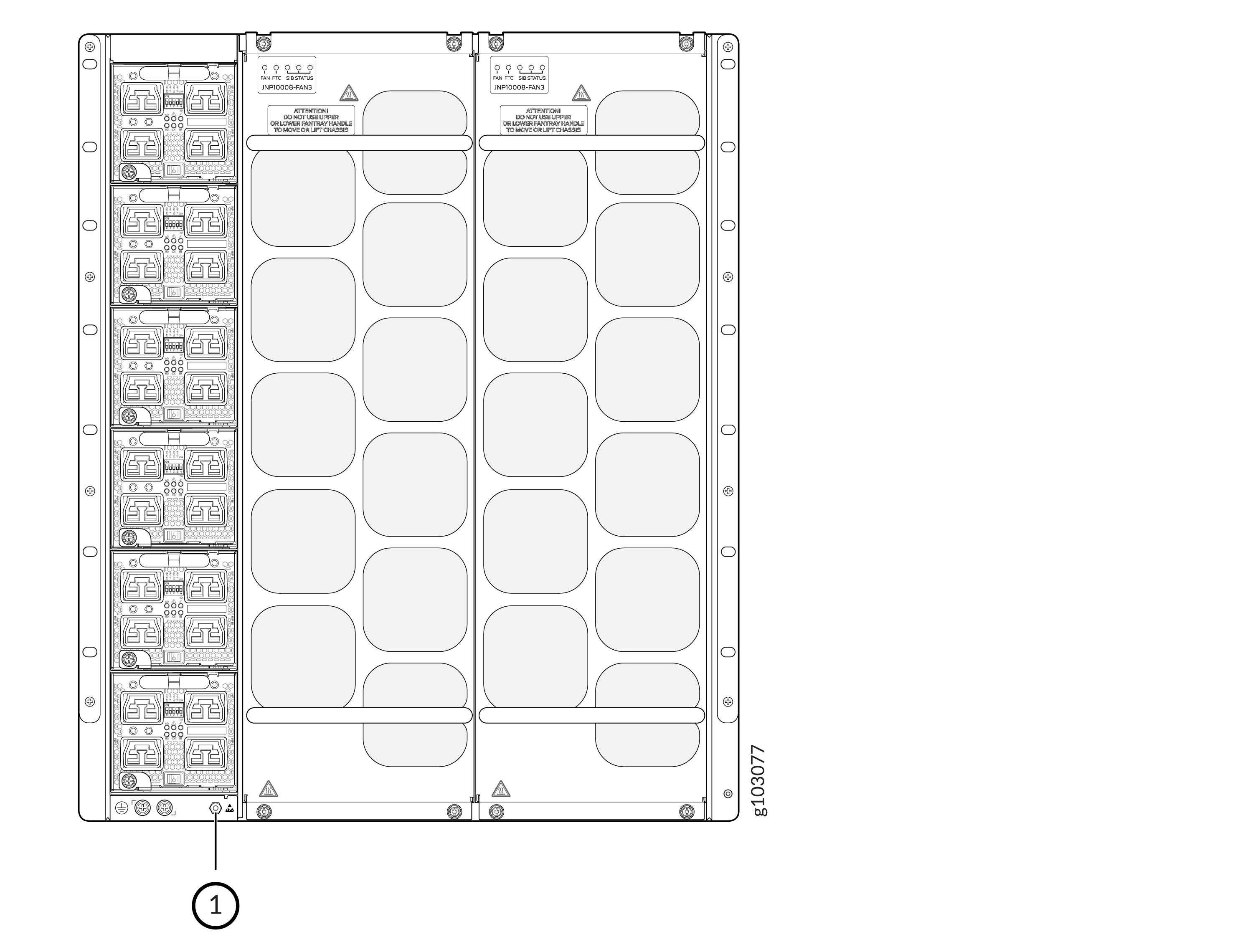
-
Wrap and fasten one end of the ESD grounding strap around your bare wrist and
connect the other end of the strap to an ESD point on the chassis. There is an ESD
point located next to the protective earthing terminal and below
PSU 5 on the rear of the MX10008 (see Figure 26).
Figure 26: ESD Point on the Rear of the MX10008
 1—
1—ESD point
-
Remove the retainers using a #1 Philips screw driver and detach the power cords
from the PSU.
Figure 27: Detach the Power Cords from JNP10K-PWR-AC3 Power Supply
-
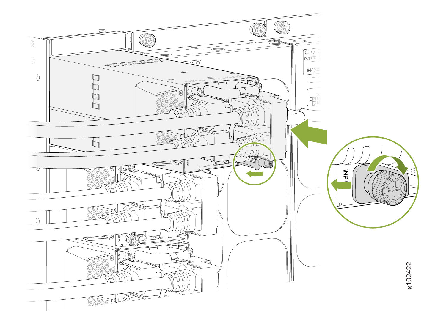
Unscrew the captive screw counterclockwise by using the
Phillips (+) screwdriver, number 1. See Figure 28.
Note:
Ensure that the ejector is fully open to avoid scratching the chassis.
Figure 28: Remove a JNP10K-PWR-AC3 Power Supply from a MX10008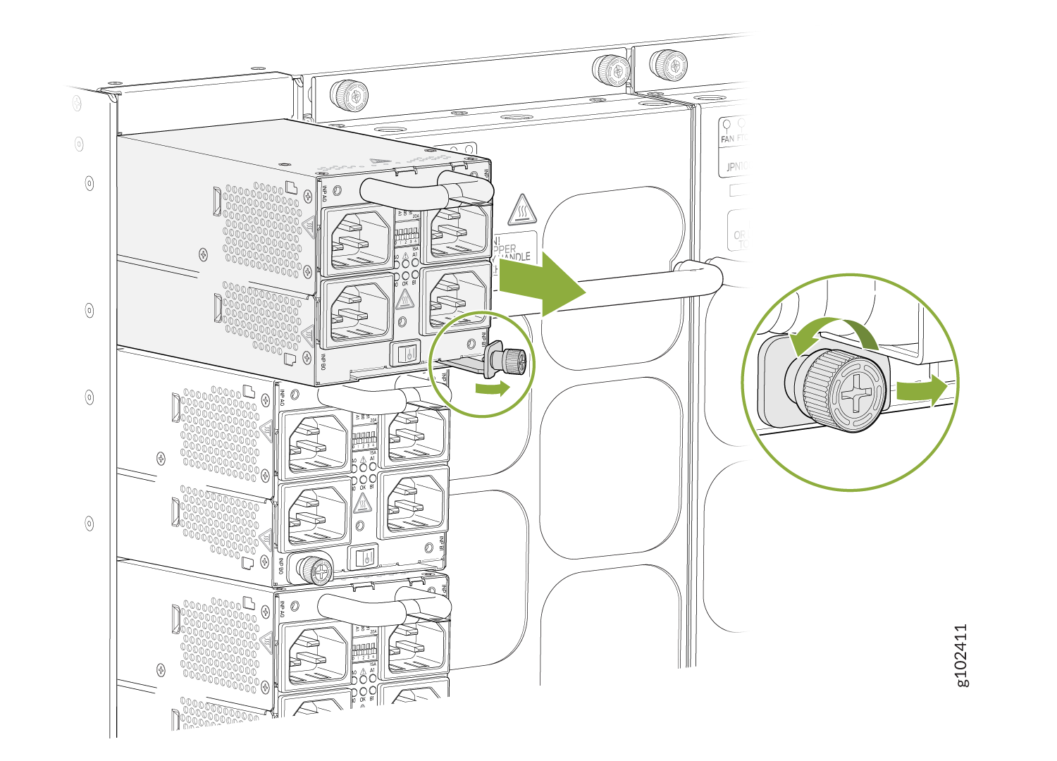
-
Wear heat protective gloves before you remove the power supply from the
chassis.

How to Install a JNP10K-PWR-AC3 Power Supply
Use the same type of power supply in all slots. Do not mix power supply models in a production chassis. The only time you are allowed to have two models concurrently running in a system is when you are in the process of swapping out all JNP10K-PWR-AC/JNP10K-PWR-AC2 power supplies with all JNP10K-PWR-AC3 power supplies.
Protect yourself from severe burns by wearing heat-protective gloves when removing a running JNP10K-PWR-AC3 power supply from the chassis. The power supply can reach temperatures between 158 °F to 176 °F (70 °C to 80 °C) when equipment is on.
Before you install a JNP10K-PWR-AC3 power supply in the chassis:
-
Ensure that you have followed all safety warnings and cautions.
-
Ensure that you understand how to prevent ESD damage. See Prevention of Electrostatic Discharge Damage.
-
If the AC power source outlets have a power switch, set them to the off (O) position. Ensure that you have the following parts and tools available to install the JNP10K-PWR-AC3 power supply:
-
Electrostatic discharge (ESD) grounding strap
-
Phillips (+) screwdriver, number 1
-
Power cables appropriate for your geographical location (for low-voltage installations) or input amperage (for high-voltage installations). See PTX10004 Power Cable Specifications.
-
To install a JNP10K-PWR-AC3 power supply in a MX10008:
-
Wrap and fasten one end of the ESD grounding strap around your bare wrist and
connect the other end of the strap to an ESD point on the chassis. There is an ESD
point located next to the protective earthing terminal and below PSU
5 on the rear of the MX10008 (see Figure 26).
Figure 29: ESD Point on the Rear of the MX10008
1—
ESD point
-
Using both hands, place the power supply in the power supply slot on the rear of
the system. Slide the power supply straight into the chassis until the power
supply is fully seated in the slot. Ensure that the power supply faceplate is
flush with any adjacent power supply faceplates or power supply covers (see How to Install a JNP10K-PWR-AC3 Power Supply).
Figure 30: Install a JNP10K-PWR-AC3
-
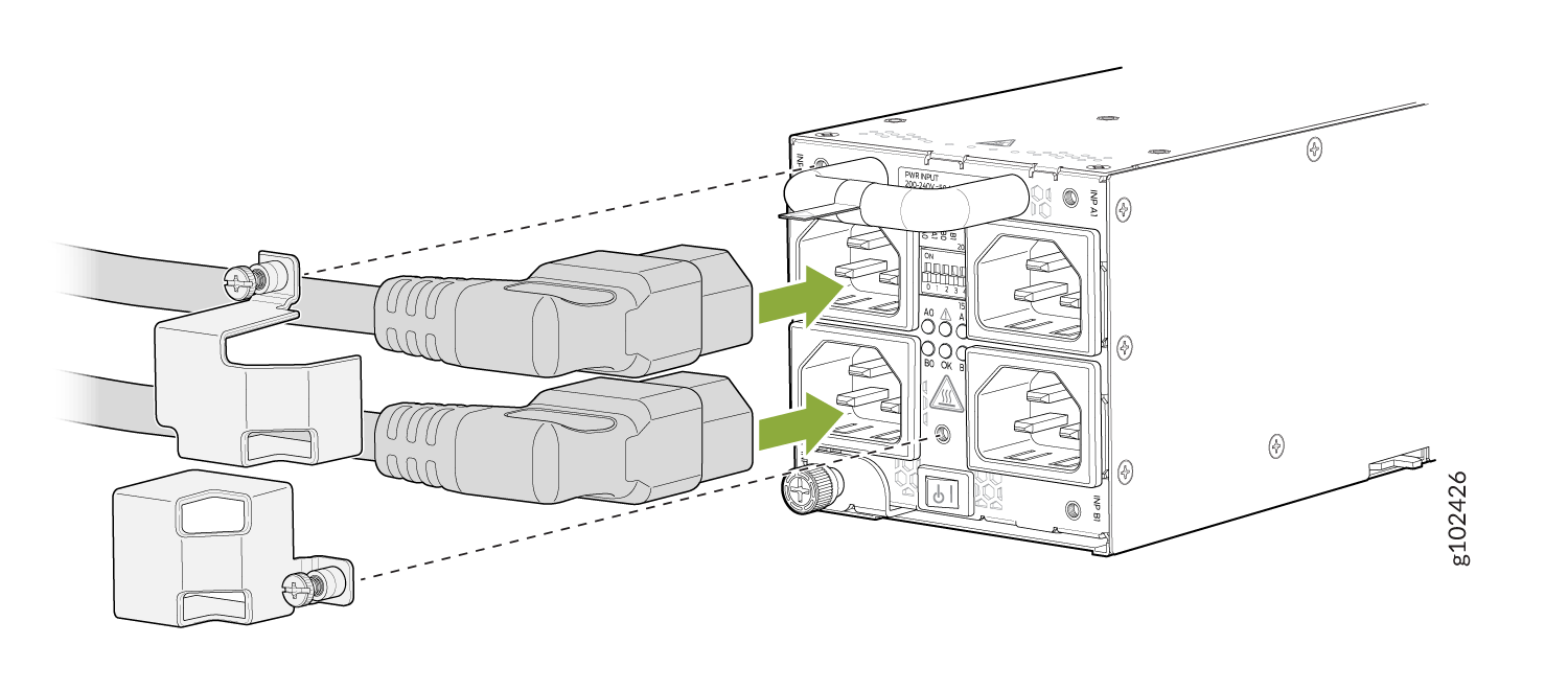
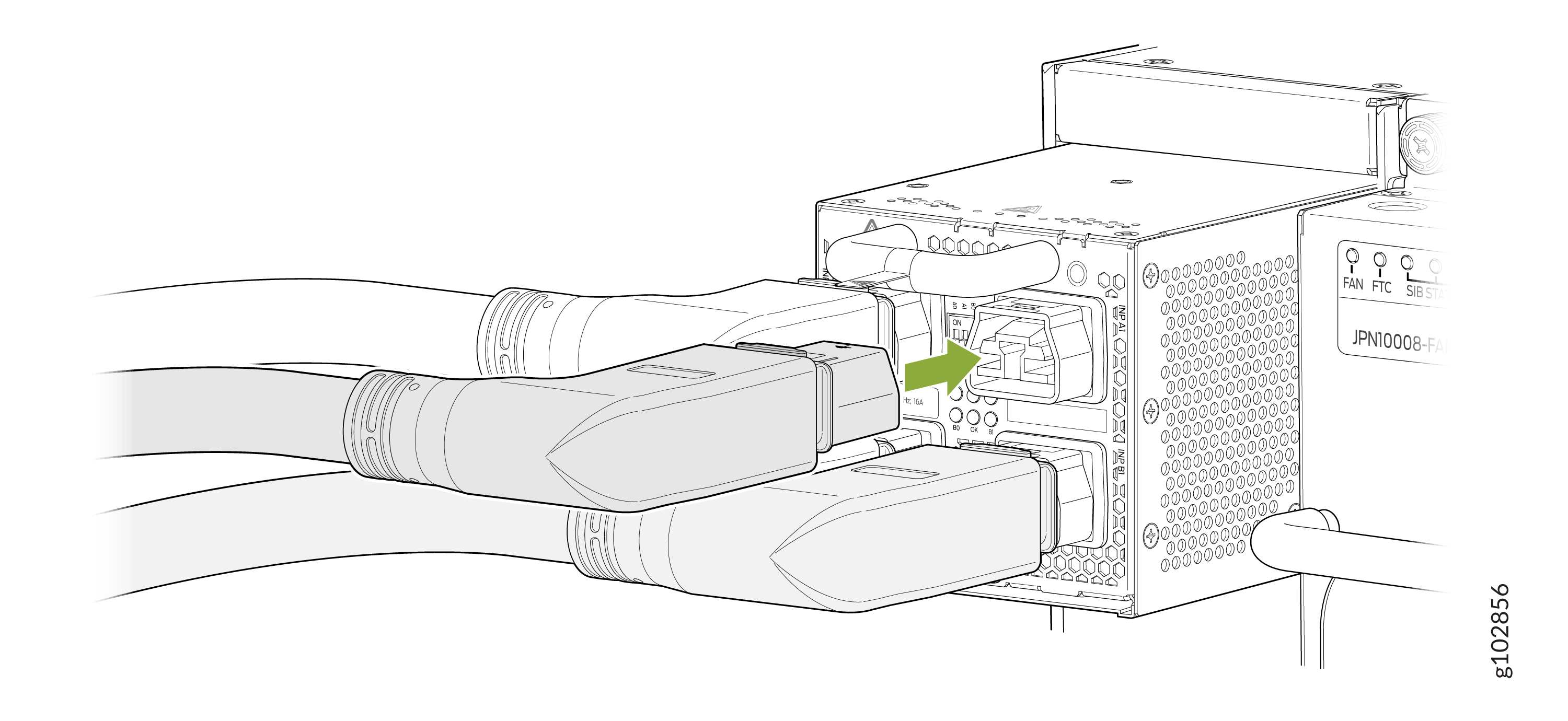
Attach each power cable to a dedicated power source (A0, B0, A1, and B1). The
JNP10K-PWR-AC3 only requires that each power supply be connected to a separate
source.
-
When installing the right angle power cords, the left column of inputs (A0
and B0) should be connected first. After connecting the A0 and/or B0 inputs,
secure the plugs using the retainer (SKU#540-175625) for the A0 plug and
retainer (SKU#540-175626) for the B0 plug. The retainers are attached to the
PSU faceplate with a single captive fastener using a #1 Philips screws
drive. See Figure 31.
Figure 31: Plug Retainers for A0 and B0 Inputs
-
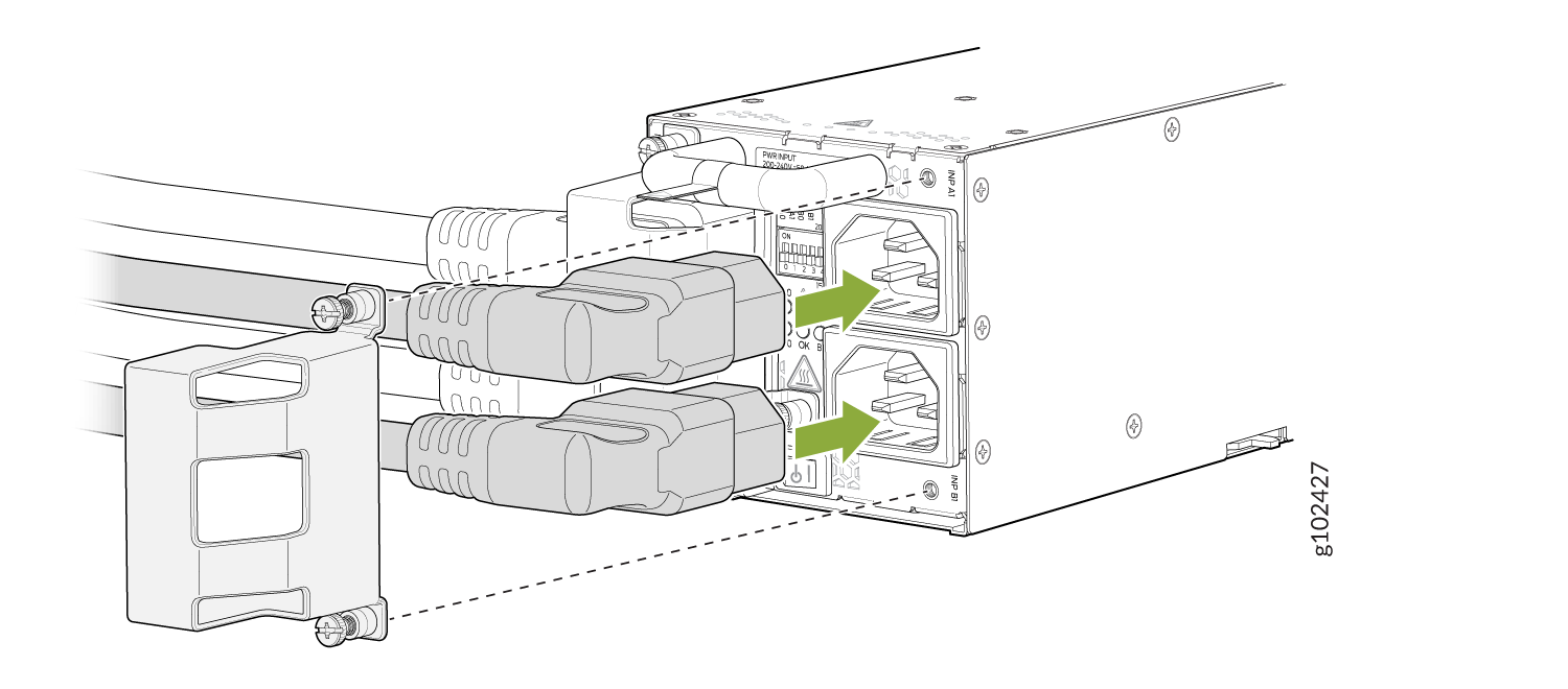
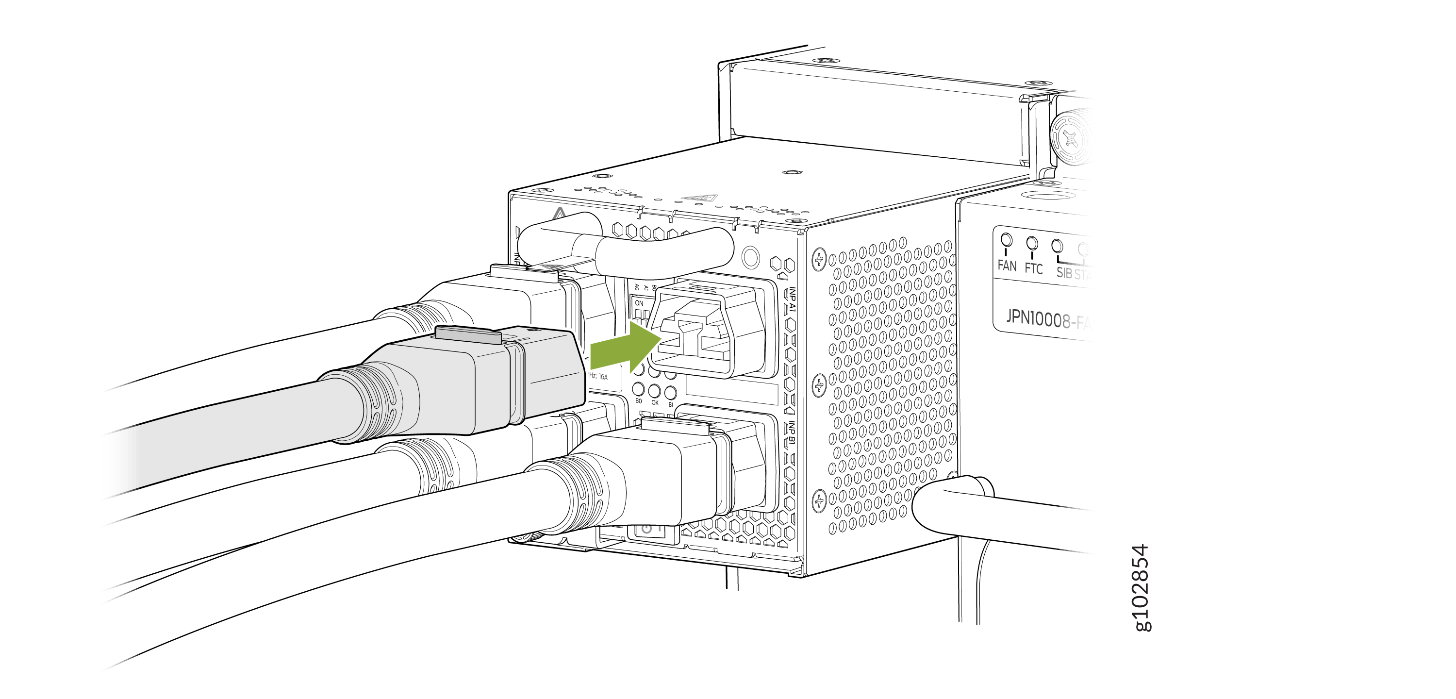
Next connect the right column of inputs (A1 and B1). After connecting the
A1 and/or B1 inputs, secure the plugs using the retainers (SKU#540-175627).
The right column plug retainer is attached to the PSU faceplate with two
captive screws using a #1 Philips screwdriver. See Figure 32.
Figure 32: Plug Retainers for A1 and B1 Inputs
-
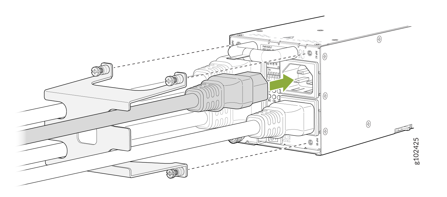
If you want to use straight power cords, you may connect the straight
power cords in any order. After connecting the straight power cords, secure
the plugs with the retainer (SKU#540-175624). The retainer is attached to
the PSU faceplate with three captive fasteners using a #1 Philips screw
driver. See Figure 33
Figure 33: Connecting Straight Power Cords
Note:Installing baffle is optional, and only to be used when you want to redirect the air flow from the left side of the PSU to the rear of the router. This ensures NEBs compliance.
The baffle should be installed before the power supply is inserted int the router. See Figure 34
Figure 34: Installing Baffle in JNPR10K-PWR-AC3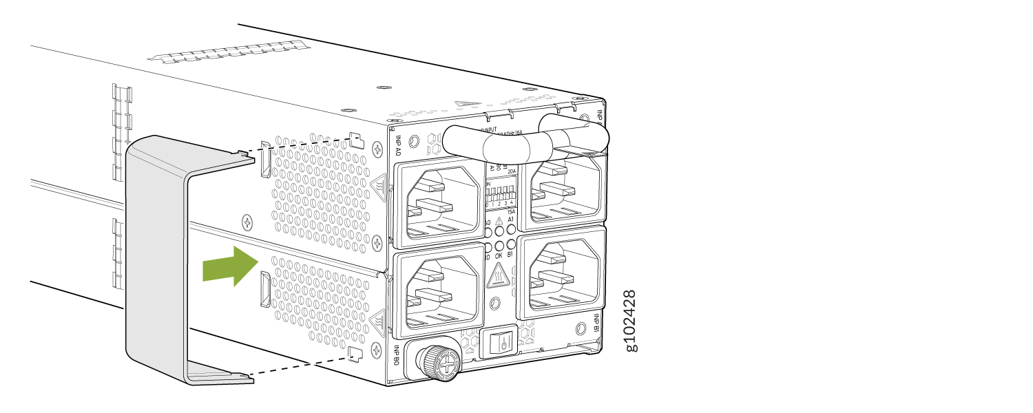
-
When installing the right angle power cords, the left column of inputs (A0
and B0) should be connected first. After connecting the A0 and/or B0 inputs,
secure the plugs using the retainer (SKU#540-175625) for the A0 plug and
retainer (SKU#540-175626) for the B0 plug. The retainers are attached to the
PSU faceplate with a single captive fastener using a #1 Philips screws
drive. See Figure 31.
-
For each power cable, insert the end of the cable with C21 connector into the
JNP10K-PWR-AC3 power supply. Use the retainers to keep the power cord in its place
in the power supply. See Figure 35
Figure 35: Installing a JNPR10K-PWR-AC3 using RA Power Cords with Baffle
 Warning:
Ensure that the power cords do not block access to router components or drape where people can trip on them.
How to Install a JNP10K-PWR-AC3H Power Supply
Use the same type of power supply in all slots. Do not mix power supply models in a production chassis. The only time you are allowed to have two models concurrently running in a system is when you are in the process of hot-swapping all JNP10K-PWR-AC/JNP10K-PWR-AC2 power supplies with JNP10K-PWR-AC3H power supplies.
Protect yourself from severe burns by wearing heat-protective gloves when removing a running JNP10K-PWR-AC3H power supply from the chassis. The power supply can reach temperatures from 158°F through 176°F (70°C to 80°C) under running conditions.
Before you install a JNP10K-PWR-AC3H power supply in the chassis:
-
Ensure that you have followed all safety warnings and cautions.
-
Ensure that you understand how to prevent ESD damage. See Prevention of Electrostatic Discharge Damage.
-
If the AC power source outlets have a power switch, set them to the off (O) position. Ensure that you have the following parts and tools available to install the JNP10K-PWR-AC3H power supply:
-
Electrostatic discharge (ESD) grounding strap
-
Phillips (+) screwdriver, number 1
-
Power cables appropriate for your geographical location (for low-voltage installations) or input amperage (for high-voltage installations). See PTX10004 Power Cable Specifications.
-
To install a JNP10K-PWR-AC3H power supply in a MX10008:
-
Wrap and fasten one end of the ESD grounding strap around your bare wrist and
connect the other end of the strap to an ESD point on the chassis. There is an ESD
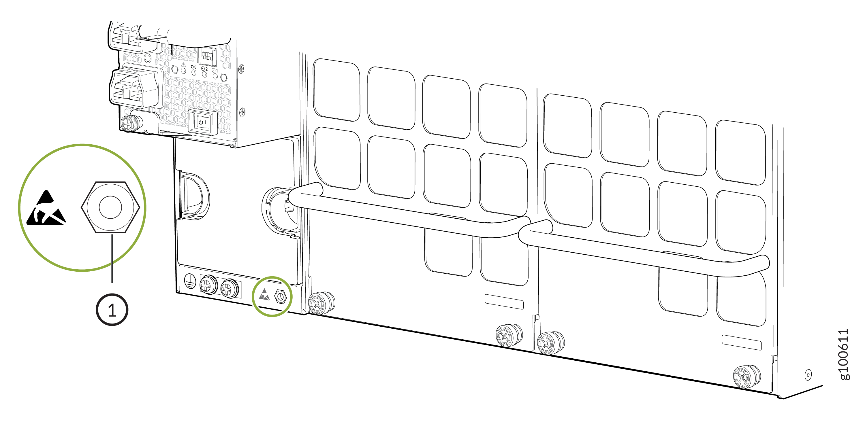
point located next to the protective earthing terminal and below PSU
2 on the rear of the MX10008 (see Figure 36).
Figure 36: ESD Point on the Rear of the MX10008
 1—
1—ESD point
-
Using both hands, place the power supply in the power supply slot on the rear of
the system. Slide the power supply straight into the chassis until the power
supply is fully seated in the slot. Ensure that the power supply faceplate is
flush with any adjacent power supply faceplates or power supply covers (see Figure 37).
Figure 37: Install a JNP10K-PWR-AC3H
-
Attach each power cable to a dedicated power source (A0, B0, A1, and B1). The
JNP10K-PWR-AC3H only requires that each power supply be connected to a separate
source. There are two types of cables that can connect the power supply unit
to the power source - one is using a straight power cord and the other is using
a right angle (RA) power cord. You can use either the straight or RA power cord
to connect the power supply to the power source. The power cord plugs and
receptacles for the JNP10K-PWR-AC3H PSU use the SAFE-D-Grid connector system.
The SAFE-D-GRID connectors have a built-in latching system, which secures the
power cord to the PSU.
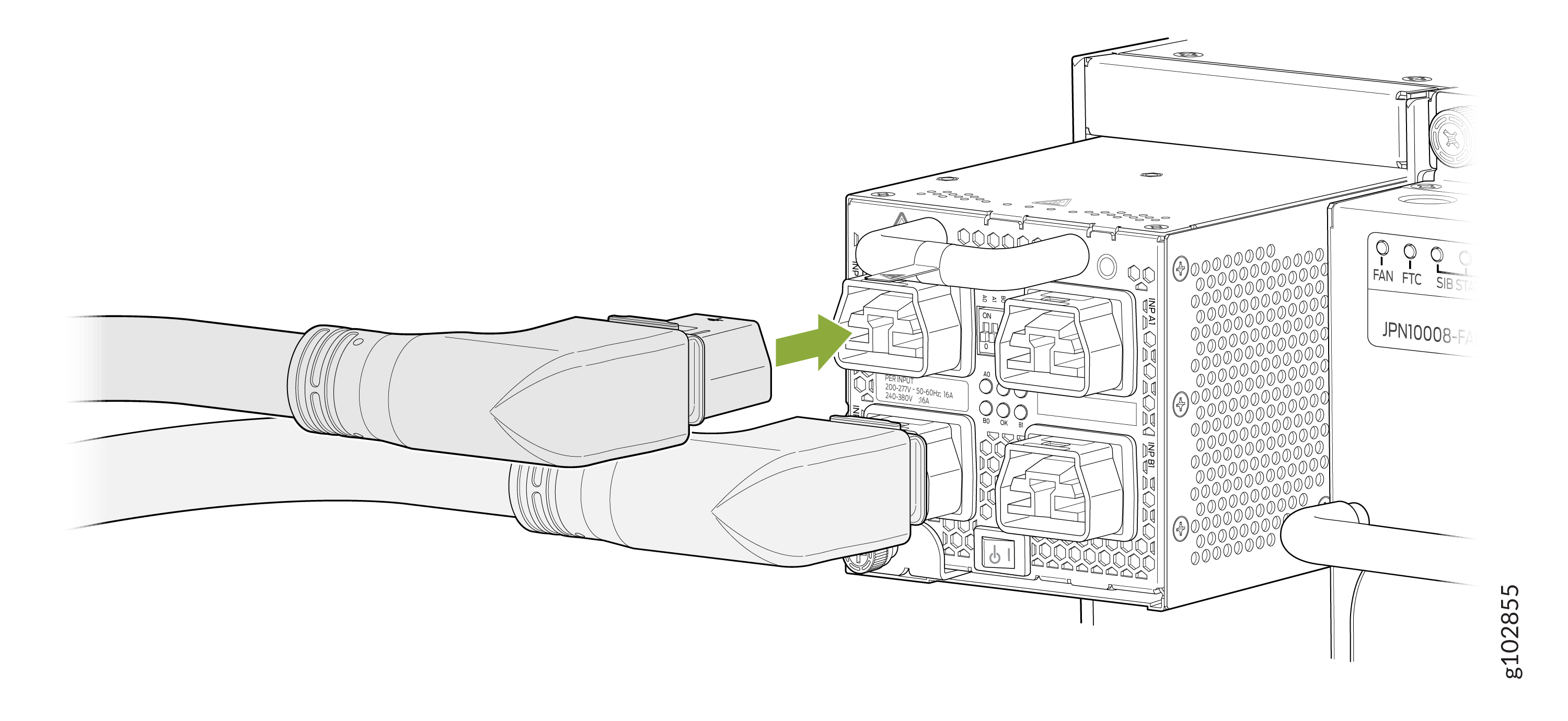
-
When installing the right angle power cords, the left column of inputs (A0
and B0) should be connected first. See Figure 31.
Figure 38: Right Angle Plugs for A0 and B0 Inputs of AC3H
-
Next connect the right column of inputs A1 and/or B1. See Figure 39.
Figure 39: Right Angle Plugs for A1 and B1 Inputs of AC3H
-
If you want to use straight power cords, you may connect the straight
power cords in any order. See Figure 33
Figure 40: Connecting Straight Power Cords to AC3H
Note:Installing baffle is optional, and only to be used when you want to redirect the air flow from the left side of the PSU to the rear of the router. This ensures NEBs compliance.
The baffle should be installed before the power supply is inserted int the router. See Figure 41.
Figure 41: Installing Baffle in JNPR10K-PWR-AC3H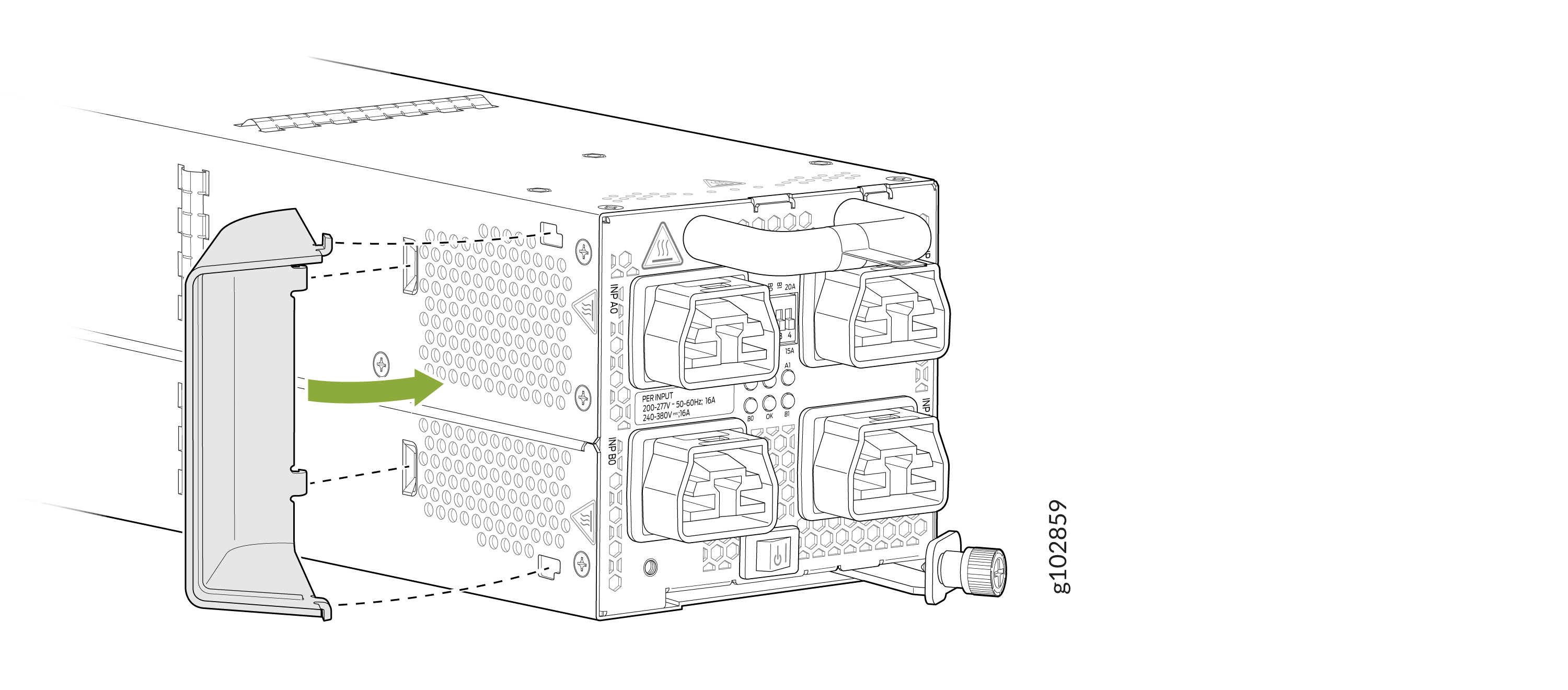
-
When installing the right angle power cords, the left column of inputs (A0
and B0) should be connected first. See Figure 31.
-
For each power cable, insert the end of the cable with C21 connector into the
JNP10K-PWR-AC3H power supply. Use the retainers to keep the power cord in its
place in the power supply. See Figure 42.
Figure 42: Installing a JNPR10K-PWR-AC3H using RA Power Cords with Baffle
Warning:
Ensure that the power cords do not block access to router components or drape where people can trip on them.
How to Remove a JNP10K-PWR-AC3H Power Supply
Before you remove a JNP10K-PWR-AC3H power supply from the chassis:
-
Ensure that you understand how to prevent ESD damage. See Prevention of Electrostatic Discharge Damage.
-
Ensure that you have the following parts and tools available:
-
Heat-protective gloves able to withstand temperatures of 158°F (70°C)
-
Electrostatic discharge (ESD) grounding strap
-
Phillips (+) screwdriver, number 1
-
Replacement power supply or a cover for the power supply slot
-
Protect yourself from severe burns by wearing heat-protective gloves when removing a working JNP10K-PWR-AC3H power supply from the chassis. These power supplies can reach temperatures between 158°F and 176°F (70°C to 80°C) under running conditions.
Before you remove a power supply, ensure that you have power supplies sufficient to power the router left in the chassis. See Power Requirements for PTX10004 Components.
Do not leave the power supply slot empty for a long time while the router is operational. Either replace the power supply promptly or install a ABPM or a cover over the empty slot.
To remove a JNP10K-PWR-AC3H power supply from a MX10008 router:
-
Wrap and fasten one end of the ESD grounding strap around your bare wrist and
connect the other end of the strap to an ESD point on the chassis. There is an ESD
point located next to the protective earthing terminal and below
PSU 2 on the rear of the MX10008 (see Figure 43).
Figure 43: ESD Point on the Rear of the MX10008 with HVAC/HVDC
1—
ESD point
-
Remove the retainers using a #1 Philips screw driver and detach the power cords
from the PSU.
Figure 44: Detach the Power Cords from JNP10K-PWR-AC3H Power Supply
-
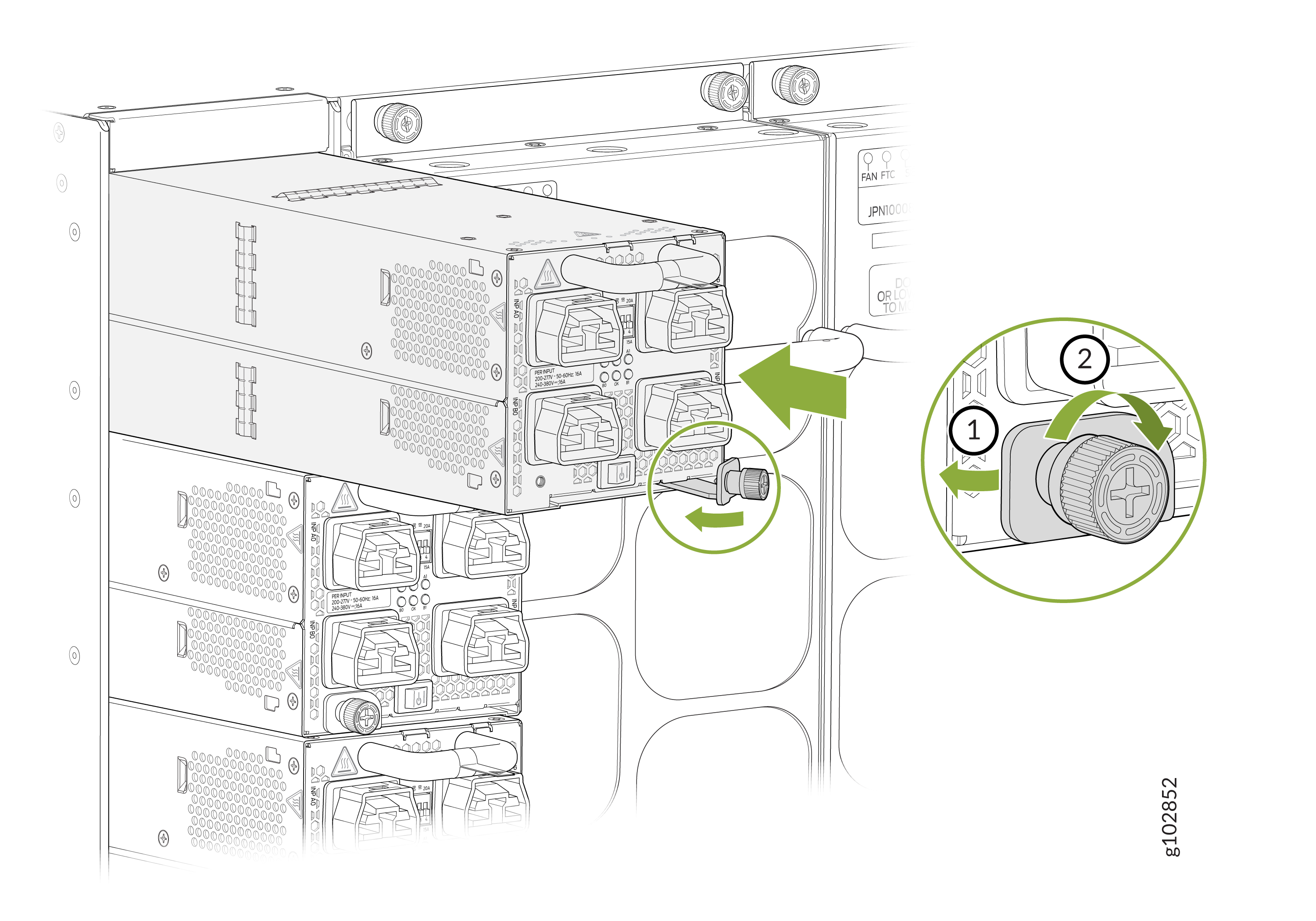
Unscrew the captive screw counterclockwise by using the
Phillips (+) screwdriver, number 1. See Figure 45.
Note:
Ensure that the ejector is fully open to avoid scratching the chassis.
Figure 45: Remove a JNP10K-PWR-AC3H Power Supply from a MX10008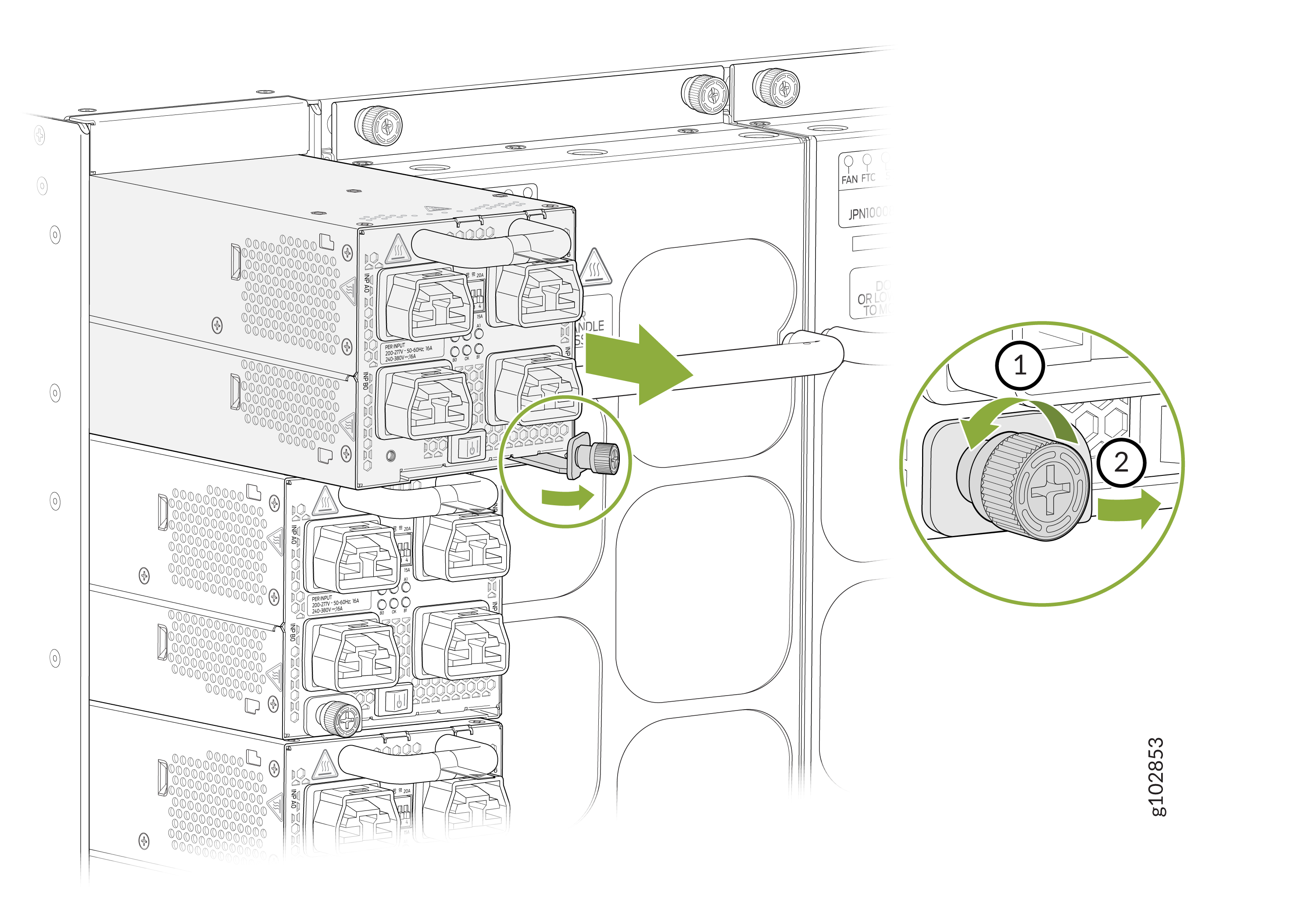
-
Wear heat protective gloves before you remove the power supply from the
chassis.
How to Remove a JNP10K-PWR-DC Power Supply
Before you remove a DC power supply from the router:
Ensure you understand how to prevent ESD damage. See Prevention of Electrostatic Discharge Damage.
Ensure that you have the following parts and tools available to remove a JNP10K-PWR-DC power supply:
Electrostatic discharge (ESD) grounding strap
Phillips (+) screwdriver, numbers 1 and 2
13/32 in. (10 mm) nut driver or socket wrench
Replacement power supply or a cover for the power supply slot
The JNP10K-PWR-DC power supply in an MX10008 and in an MX10016 chassis is a hot-removable and hot-insertable field-replaceable unit (FRU). You remove DC power supplies from the rear of the chassis.
Before you remove a power supply, ensure that sufficient power supplies are left in the chassis to power the router (see Calculate Power Requirements for an MX10008 Router).
Before performing DC power procedures, ensure that power is removed from the DC circuit. To ensure that all power is off, locate the circuit breaker on the panel board that services the DC circuit, router the circuit breaker to the OFF position, and tape the router handle of the circuit breaker in the OFF position.
Do not leave the power supply slot empty for a long time while the router is operational. Either replace the power supply promptly or install a cover panel over the empty slot.
To remove a JNP10K-PWR-DC power supply from an MX10000 router:
- Attach the electrostatic discharge (ESD) grounding strap
to your bare wrist, and connect the strap to the ESD point on the
chassis. There is an ESD point located next to the protective earthing
terminal and below PSU 5 on the MX10008
rear panel (see Figure 46) and
below PSU_9 on the MX10016 (see Figure 47).Figure 46: ESD Point on an MX10008 Chassis Rear1—
ESD point
Figure 47: ESD Point on an MX10016 Chassis Rear1—ESD point
- Rotate the captive screw away from the faceplate of the
power supply to release the latch. See Figure 48 and Figure 49.Figure 48: Removing a JNP10K-PWR-DC Power Supply from an MX10008
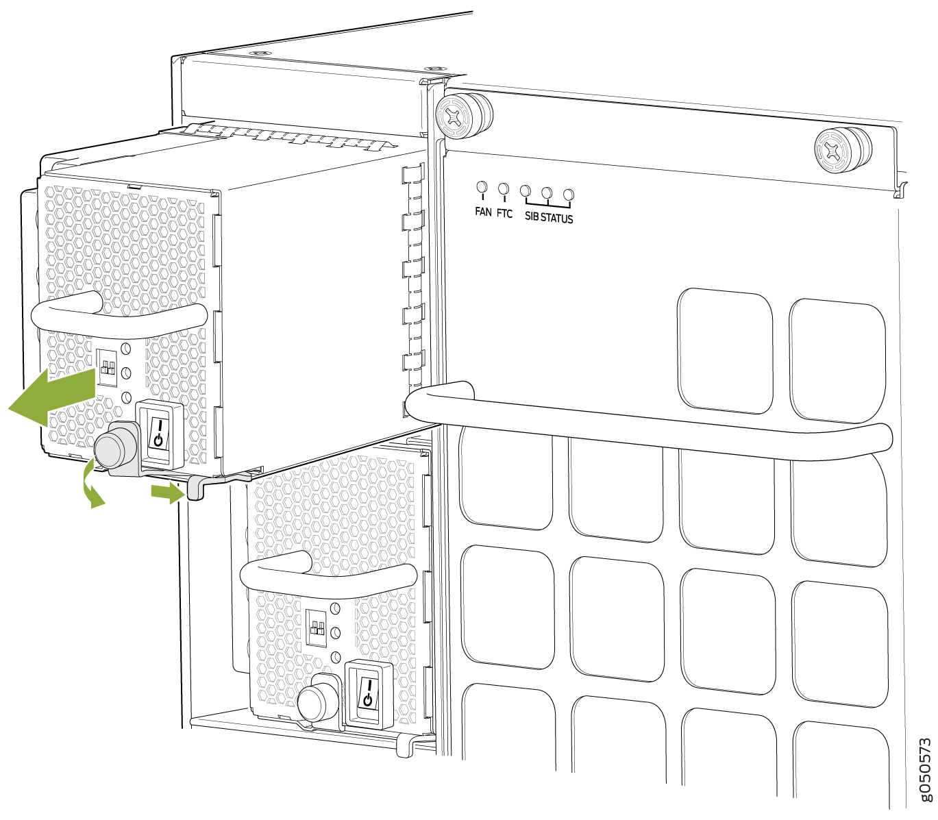 Figure 49: Removing a JNP10K-PWR-DC Supply from an MX10016
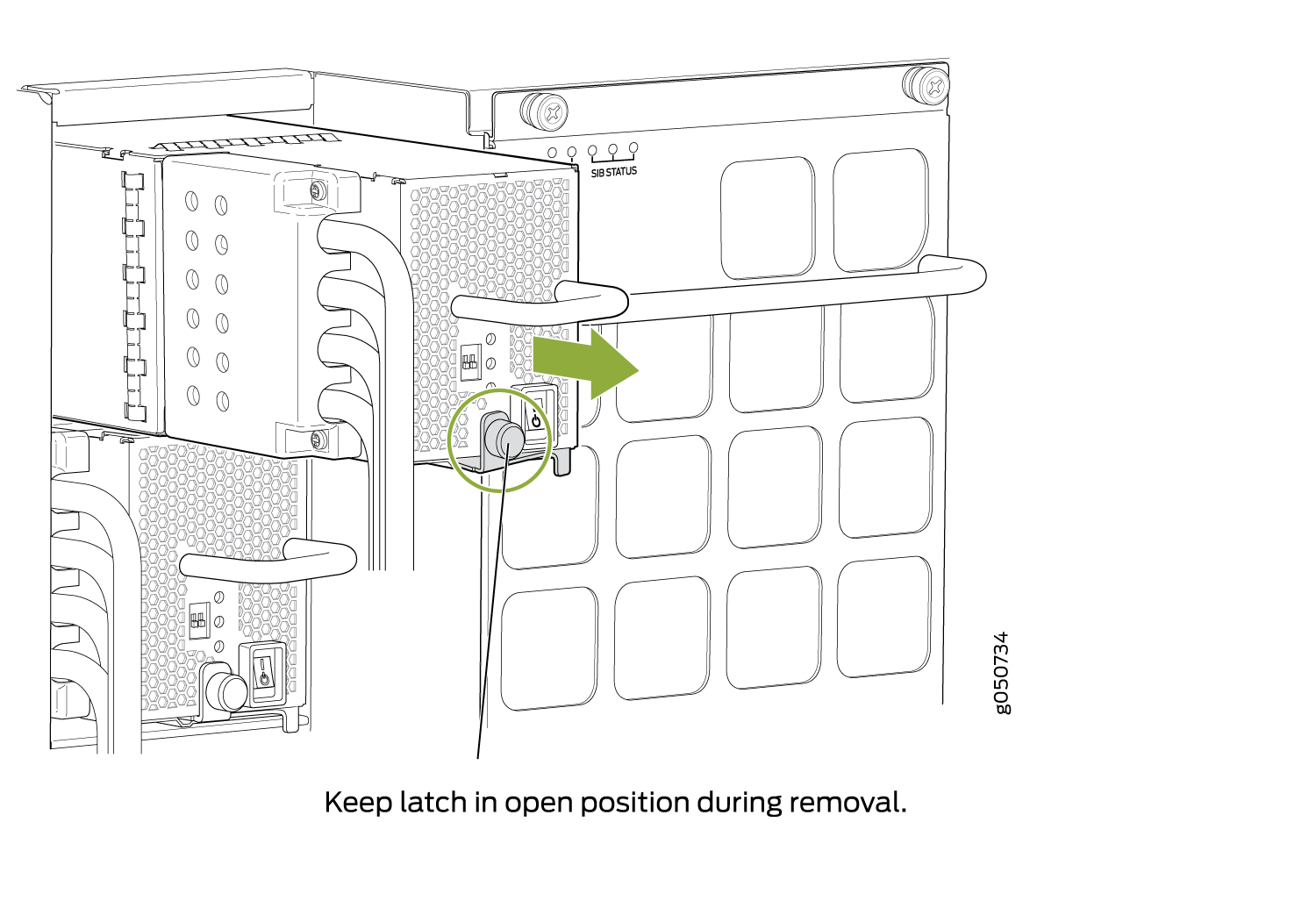 Note:
Note:Ensure that the ejector is fully open to avoid scratching the chassis.
- Taking care not to touch power supply components, pins,
leads, or solder connections, place one hand under the power supply
to support it. Grasp the power supply handle with your other hand
and pull the power supply completely out of the chassis.CAUTION:
See the heat symbol
. The power supply surfaces are hot. Allow a few minutes for the
power supply to cool by pulling the power supply halfway out of the
chassis, or wear heat-resistant gloves while removing the power supply.
See Also
How to Install a JNP10K-PWR-DC Power Supply
Before you install a JNP10K-PWR-DC power supply in the chassis, ensure that you have followed all safety warnings and cautions:
Before performing DC power procedures, ensure that power is removed from the DC circuit. To ensure that all power is off, locate the circuit breaker on the panel board that services the DC circuit, router the circuit breaker to the OFF position, and tape the router handle of the circuit breaker in the OFF position.
Before you connect power to the router, a licensed electrician must attach a cable lug to the grounding and power cables that you supply. A cable with an incorrectly attached lug can damage the router (for example, by causing a short circuit).
Do not mix AC and DC power supplies in the same chassis.
To meet safety and electromagnetic interference (EMI) requirements and to ensure proper operation, you must connect MX10000 routers to earth ground before you connect them to power. For installations that require a separate grounding conductor to the chassis, use the protective earthing terminal on the router chassis to connect to earth ground. For instructions on connecting an MX10000 router to ground using a separate grounding conductor, see Connect the MX10008 to Earth Ground.
Each battery return of the DC power supply must be connected as an isolated DC return (DC-I).
Ensure you understand how to prevent ESD damage. See Prevention of Electrostatic Discharge Damage.
Ensure that you have the following parts and tools available to install a JNP10K-PWR-DC power supply:
Electrostatic discharge (ESD) grounding strap
DC power source cables (not provided) with the cable lugs (provided) attached
The provided terminal lugs in an MX10000 are sized for either4 AWG (21.1 mm2) or 6 AWG (13.3 mm2) power source cables. When running all JNP10K-PWR-DC power supply modules in the chassis, the DC power source cables that you provide must be 6 AWG (13.3 2) mm²) stranded wire We recommend that you install heat-shrink tubing insulation around the crimped section of the power cables and lugs.
Note:If you upgrade the JNP10K-PWR-DC to a JNP10K-PWR-DC2 and set the input mode to high (80-A), you must use 4 AWG (21.1 mm²) stranded wire.
Note:See the heat symbol
.
Wear heat-resistant gloves while accessing the fan tray and power
supply.13/32 in. (10 mm) nut driver or socket wrench
Phillips (+) screwdrivers, numbers 1 and 2
Multimeter
The JNP10K-PWR-DC power supply in an MX10008 and MX10016 chassis is a hot-removable and hot-insertable field-replaceable unit (FRU). You can install up to 6 JNP10K-PWR-DC power supplies in an MX10008 router chassis and 10 in an MX10016 router chassis. All power supplies install in the rear of the chassis in the slots along the left side of the chassis.
To install a JNP10K-PWR-DC power supply in an MX10000:
- Attach the electrostatic discharge (ESD) grounding strap
to your bare wrist, and connect the strap to the ESD point on the
chassis. There is an ESD point located next to the protective earthing
terminal and below PSU 5 on the MX10008
rear panel (see Figure 50) and below PSU_9 on the MX10016 rear panel
(see Figure 51).Figure 50: ESD Point on MX10008 Chassis Rear1—
ESD point
Figure 51: ESD Point on an MX10016 Chassis Rear1—ESD point
- Taking care not to touch power supply components, pins,
leads, or solder connections, remove the power supply from its bag.CAUTION:
See the heat symbol
. The power supply surfaces are hot. Allow a few minutes for the
power supply to cool by pulling the power supply halfway out of the
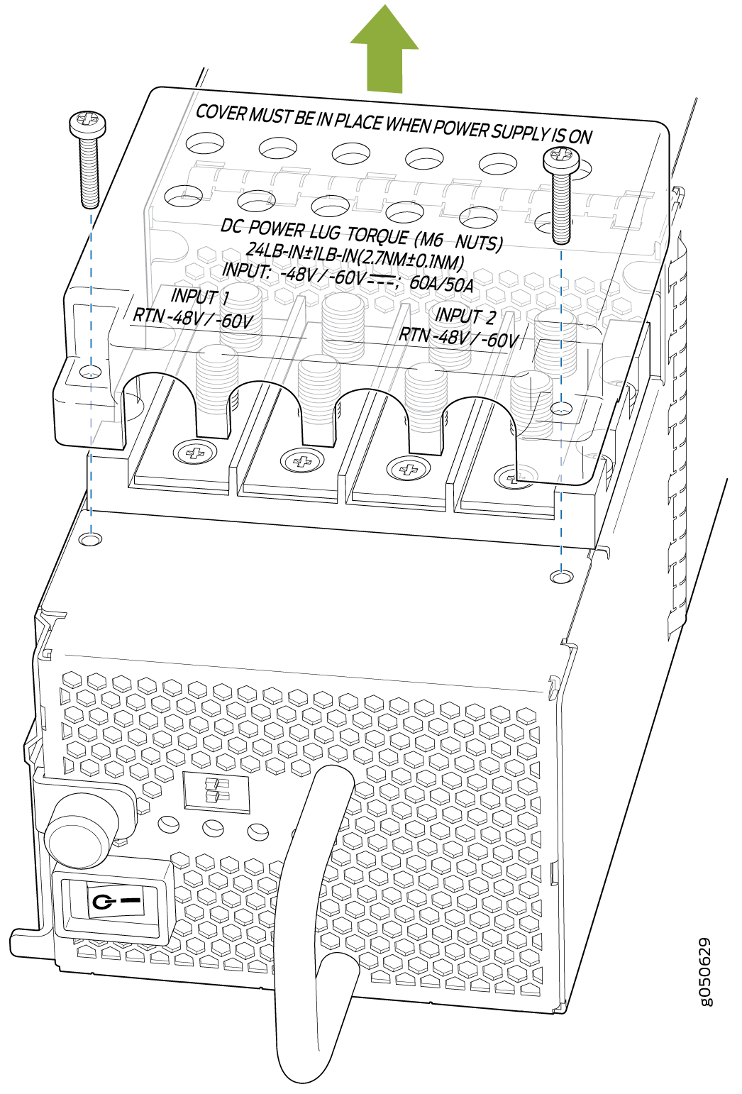
chassis, or wear heat-resistant gloves while removing the power supply. - Remove the plastic cable cover from the DC power input
terminals by using the Phillips (+) screwdriver, number 2,
to loosen the screws (see Figure 52).Figure 52: Removing the Plastic Cable Cover on an MX10008 DC Power Supply
-
Install heat-shrink tubing insulation around the power
cables.
To install heat-shrink tubing:
-
Slide the tubing over the portion of the cable where it is attached to the lug barrel. Ensure that tubing covers the end of the wire and the barrel of the lug attached to it.
-
Shrink the tubing with a heat gun. Ensure that you heat all sides of the tubing evenly so that it shrinks around the cable tightly.
Figure 53 shows the steps to install heat-shrink tubing.
Note:Do not overheat the tubing.
Figure 53: How to Install Heat-Shrink Tubing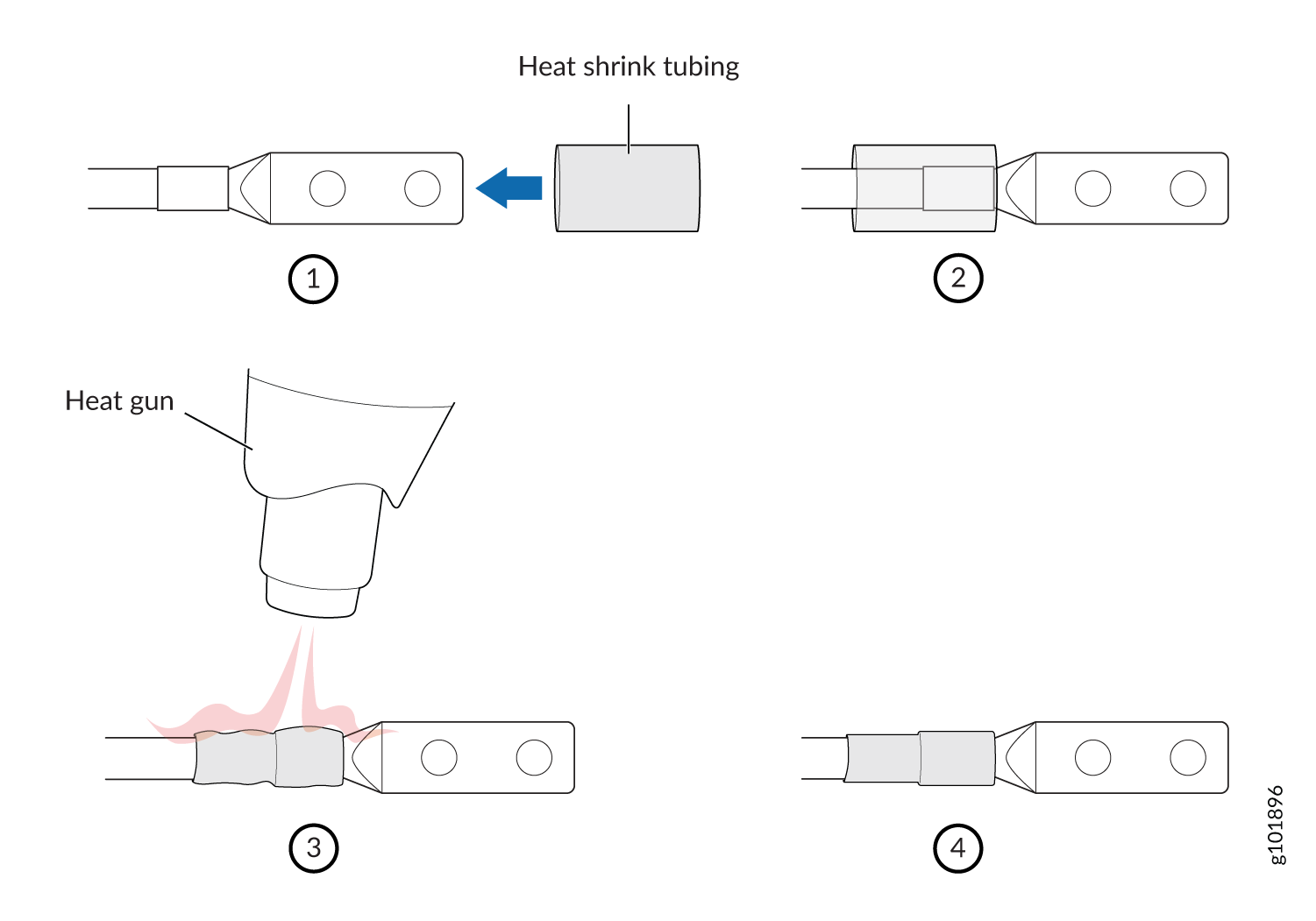
-
- Install each power cable lug on the DC power input terminal,
securing it with the nut (see Figure 54). Apply between
24 in.-lb (2.7 Nm) and 25 in.-lb (2.8 Nm) of torque
to each nut. (Use the 13/32 in. [10 mm] nut driver or socket
wrench.)
Secure each positive (+) DC source power cable lug to the RTN (return) DC power input terminal.
Secure each negative (–) DC source power cable lug to the –48V (input) DC power input terminal.
Figure 54: Connecting the DC Power Supply Cables to an JNP10K-PWR-DC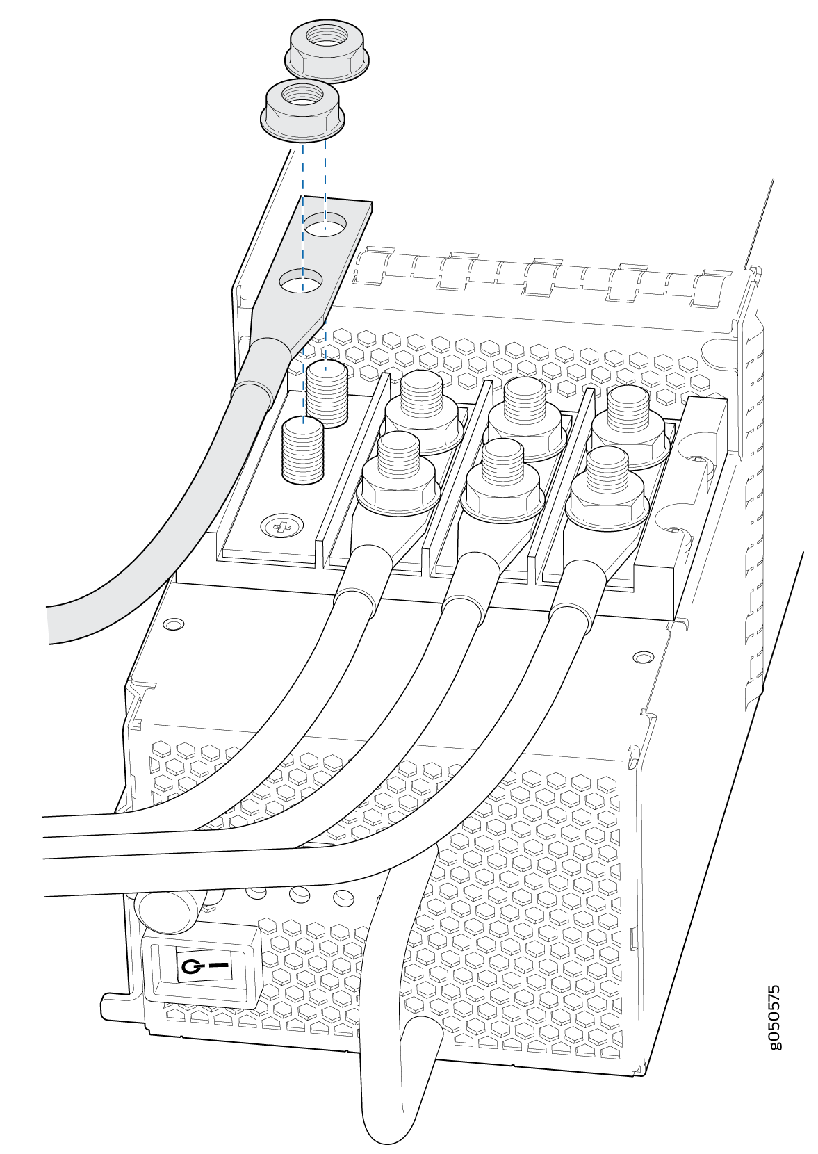
Each power supply has two independent sets of DC power input terminals (INPUT 1: RTN –48V/–60V: and INPUT 2: : RTN –48V/–60V). For feed redundancy, each power supply must be powered by dedicated power feeds derived from feed INPUT 1 and feed INPUT 2. This configuration provides the commonly deployed INPUT 1 / INPUT 2 feed redundancy for the router. There is basic insulation between the inputs and the chassis ground. Also, there is basic insulation between RTN input feeds.
- If the power supply slot on the chassis has a cover panel
on it, insert your thumb and forefinger into the finger holes, squeeze,
and pull the cover out of the slot. Save the cover panel for later
use (see Figure 55 for MX10008
installations and Figure 56 for
MX10016 installations).Figure 55: Removing the PSU Cover Panel on an MX10008Figure 56: Removing the Power Supply Cover Panel on an MX10016

- Tighten the captive screw by turning it clockwise by using
the Phillips (+) screwdriver, number 1. When the screw
is completely tight, the latch locks into the router chassis.Figure 57: Installing a JNP10K-PWR-DC Power Supply in an MX10008
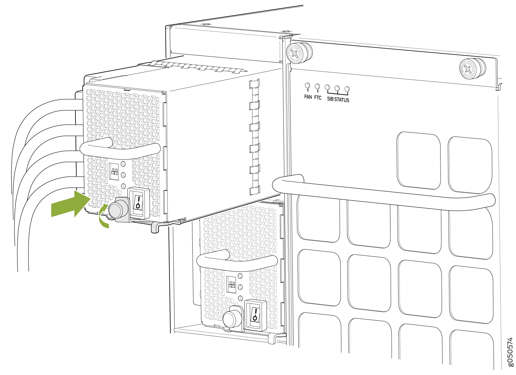 Figure 58: Installing a JNP10K-PWR-DC Power Supply in an MX10016
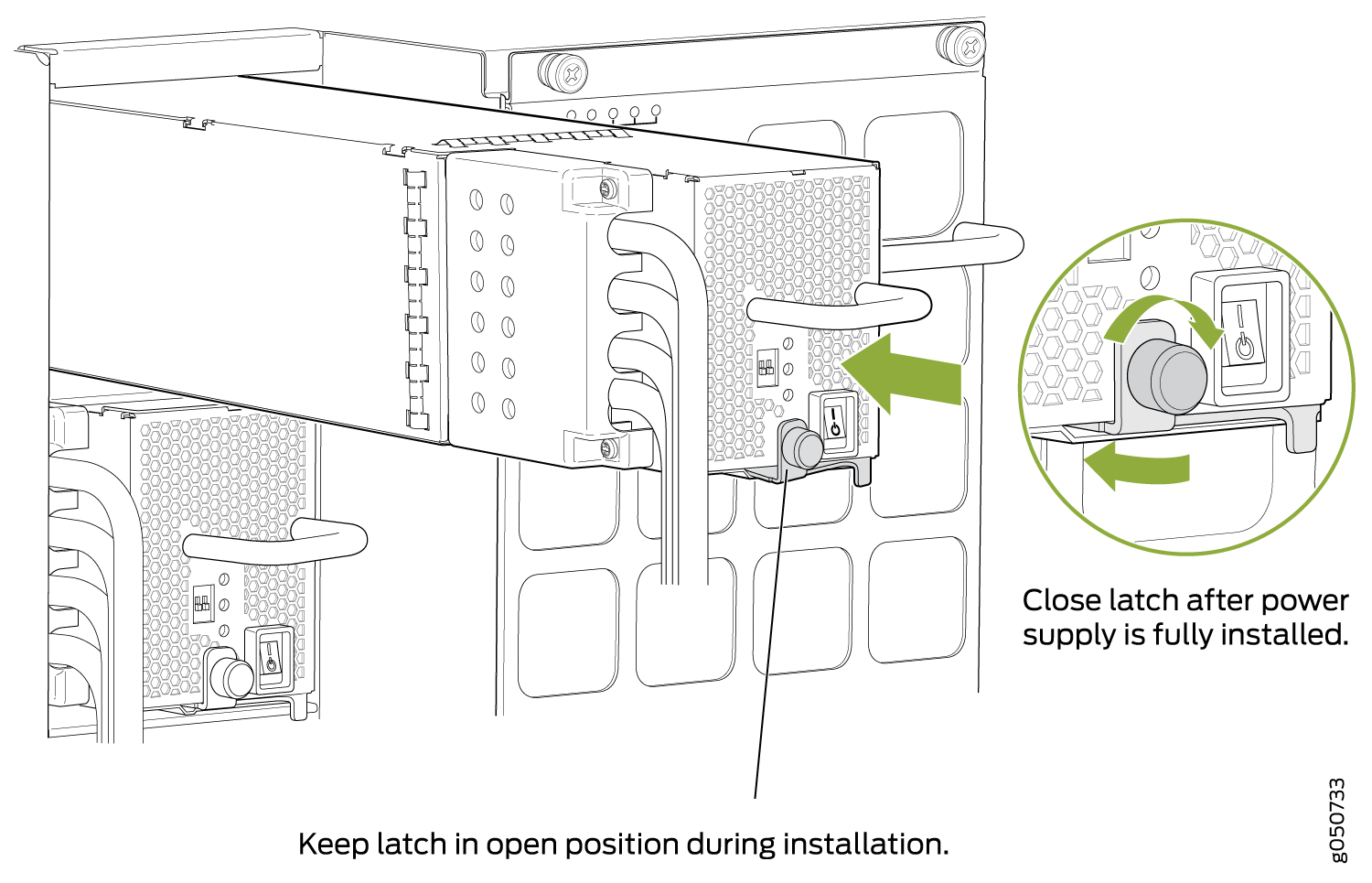 Note:
Note:Ensure that the ejector is fully open to avoid scratching the chassis.
- Route INP1 cables to a power source and INP2 to another
power source. The JNP10K-PWR-DC shares power, so if power dips on
one input, the power supply is able to load balance internally. See Figure 59 and Figure 60.Figure 59: Proper Load Balancing for JNP10K-PWR-DC Power Cables on MX10008
 Figure 60: Proper Load Balancing for JNP10K-PWR-DC Power Cables on MX100016
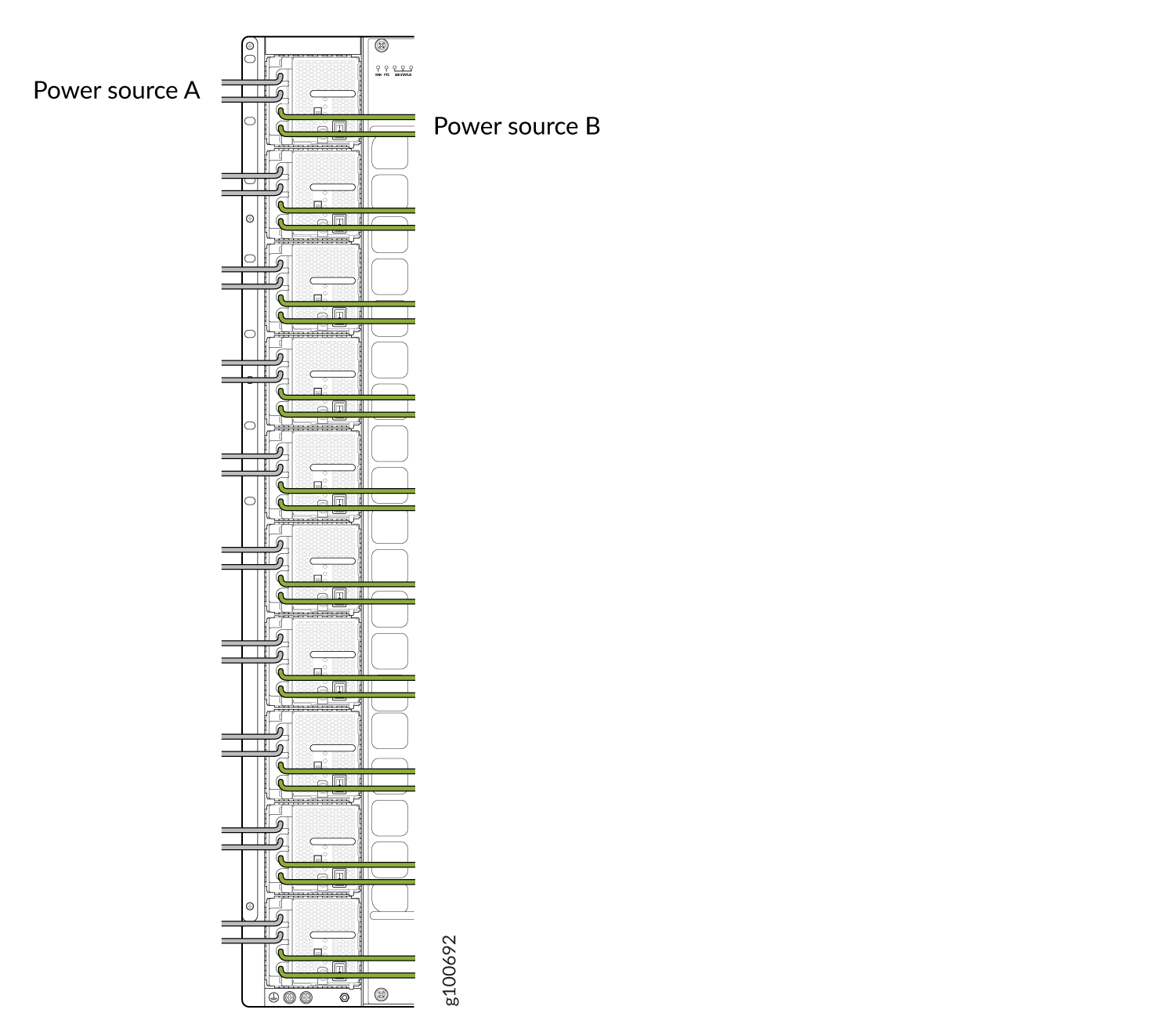 Warning:
Ensure that the power cords do not block access to router components or drape where people can trip on them.
- Set the enable switches for input 1 and input 2 (see Figure 61).
Set both enable switches to the | (on) position when using both source inputs. When not using source redundancy, set the unused source to the O (off) position. The LED turns red and indicates an error if a source input is not in use and the enable switch is | (on).
Figure 61: Setting the Enable Switches for the Power Source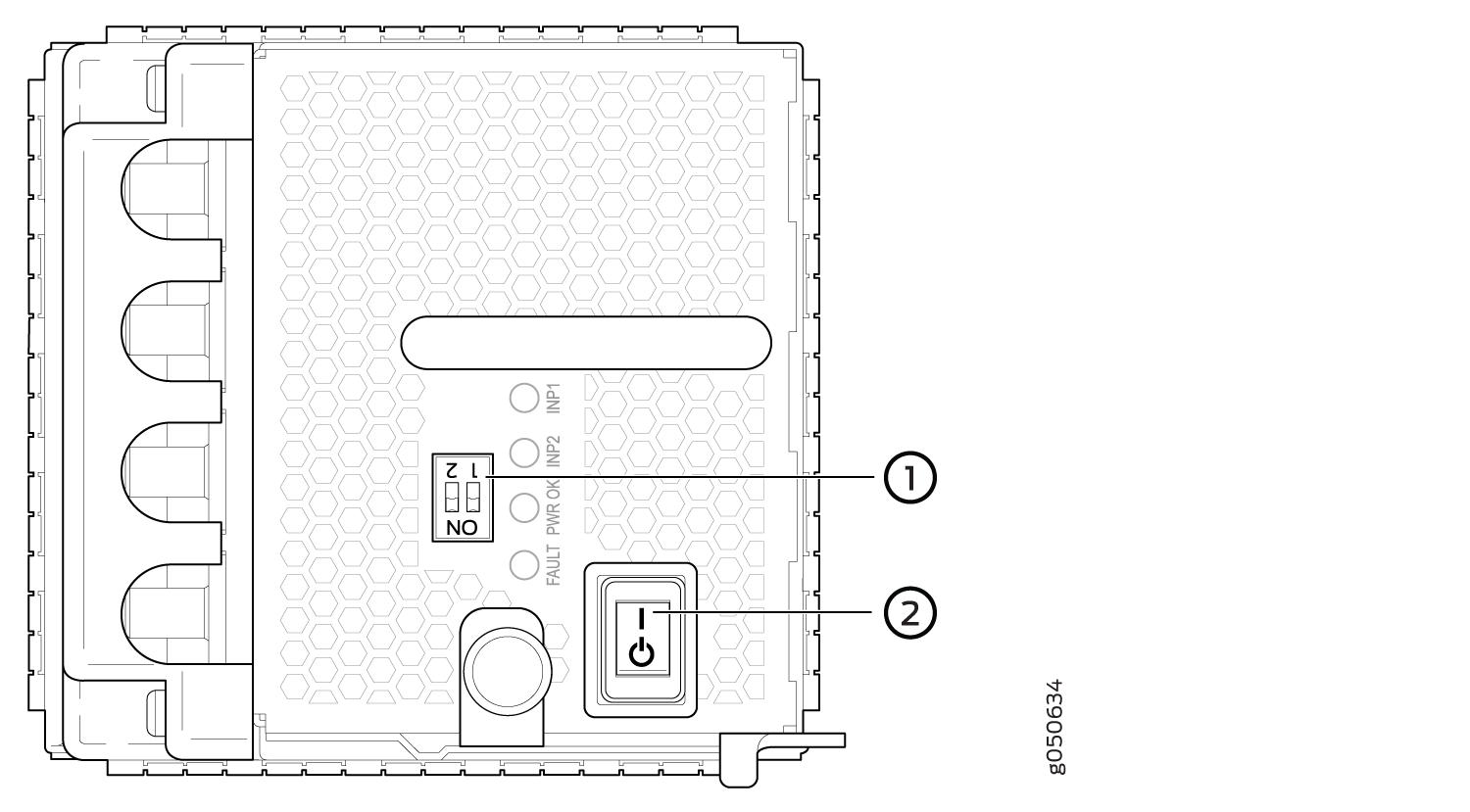 1—
1—Dip switches for enabling input sources
2—Power switch, on (|) and standby (o)
See Also
How to Remove a JNP10K-PWR-DC2 Power Supply
Before you remove a DC power supply from the router:
-
Ensure you understand how to prevent ESD damage. See Prevention of Electrostatic Discharge Damage.
Ensure that you have the following parts and tools available to remove a JNP10K-PWR-DC2 power supply:
-
Heat protective gloves able to withstand temperatures of 158°F (70°C)
-
Electrostatic discharge (ESD) grounding strap
-
Phillips (+) screwdriver, numbers 1 and 2
-
13/32 in. (10 mm) nut driver or socket wrench
-
Replacement power supply or a cover panel for the power supply slot
The JNP10K-PWR-DC2 power supply in an MX10000 chassis is a hot-removable and hot-insertable field-replaceable unit (FRU). You remove power supplies from the rear of the chassis.
A working JNP10K-PWR-DC2 power supply can reach temperatures of 158°F (70°C); In order to avoid injury, do not touch a running power supply with your bare hands.
Before you remove a power supply, ensure that you have power supplies sufficient to power the router left in the chassis. See Calculate Power Requirements for an MX10008 Router, Calculating Power Requirements for an MX10016 , and Calculate Power Requirements for an MX10008 Router.
Do not leave the power supply slot empty for a long time while the router is operational. Either replace the power supply promptly or install a cover panel over the empty slot.
To remove a JNP10K-PWR-DC2 power supply from an MX10000 router:
-
Attach the electrostatic discharge (ESD) grounding strap to your bare wrist, and
connect the strap to the ESD point on the chassis. There is an ESD point located
next to the protective earthing terminal and below PSU 5 on
the MX10008 rear panel (see Figure 62 and below
PSU_9 on the MX10016 (see Figure 63).
Figure 62: ESD Point on an MX10008 Chassis Rear
1—
ESD point
Figure 63: ESD Point on MX10016 Chassis Rear
1—ESD point
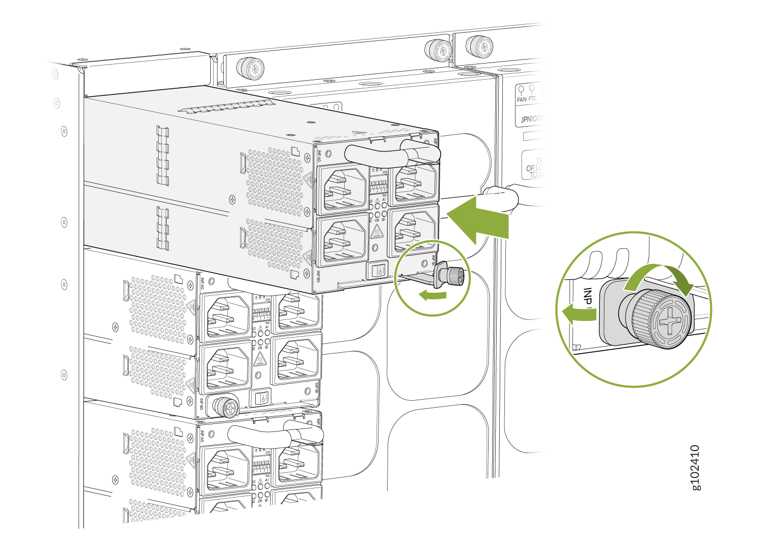
-
Rotate the captive screw away from the faceplate of the power supply to release
the latch. (See Figure 64 and
Figure 65.)
Figure 64: Removing a JNP10K-PWR-DC2 Power Supply on an MX10008
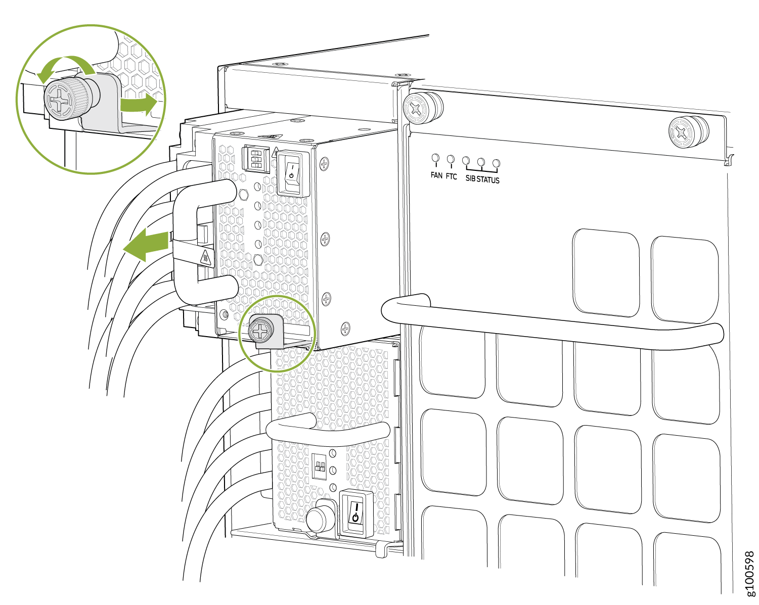 Figure 65: Removing a JNP10K-PWR-DC2 Power Supply on an MX10016
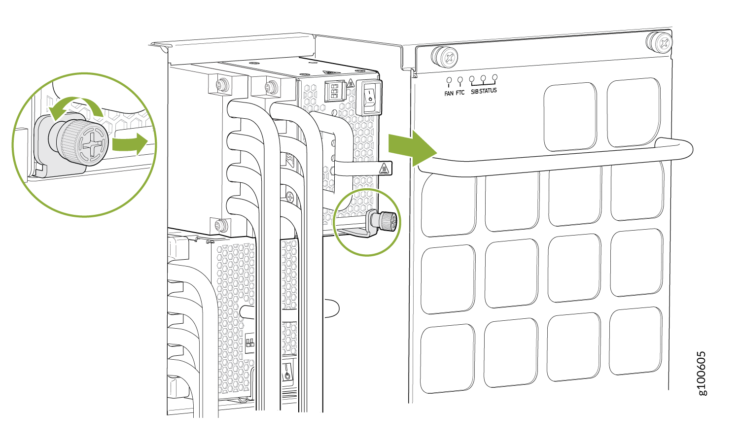
How to Install a JNP10K-PWR-DC2 Power Supply
Before you install an HVDC power supply in the chassis, ensure that you have followed all safety warnings and cautions:
Before performing DC power procedures, ensure that power is removed from the DC circuit. To ensure that all power is off, locate the circuit breaker on the panel board that services the DC circuit, router the circuit breaker to the OFF position, and tape the router handle of the circuit breaker in the OFF position.
Protect yourself from severe burns by wearing heat-protective gloves when removing a working HVDC power supply from the chassis. HVDC power supplies can reach 158°F(70°C).
Before you connect power to the router, a licensed electrician must attach a cable lug to the grounding and power cables that you supply. A cable with an incorrectly attached lug can damage the router (for example, by causing a short circuit).
Do not mix AC, DC, or HVDC power supplies in the same running chassis. You can mix DC and HVDC power supplies while swapping out one type for another during installation.
To meet safety and electromagnetic interference (EMI) requirements and to ensure proper operation, you must connect MX10008 routers to earth ground before you connect them to power. For installations that require a separate grounding conductor to the chassis, use the protective earthing terminal on the router chassis to connect to earth ground. For instructions on connecting an MX10000 router to ground using a separate grounding conductor, see Connect the MX10008 to Earth Ground.
The battery returns of the JNP10K-PWR-DC2 power supply must be connected as an isolated DC return (DC-I).
-
Ensure you understand how to prevent ESD damage. See Prevention of Electrostatic Discharge Damage.
-
Ensure that you have the following parts and tools available to install a DC power supply:
-
Electrostatic discharge (ESD) grounding strap
-
The terminal lugs for the JNP10K-PWR-DC2 are Panduit LCD4-14A-L, or equivalent, and sized for 4 AWG (21.1 mm2) power source cables. We recommend that you install heat-shrink tubing insulation around the crimped section of the power cables and lugs.
-
13/32 in. (10 mm) nut driver or socket wrench
-
Phillips (+) screwdrivers, numbers 1 and 2
-
Multimeter
-
The JNP10K-PWR-DC2 power supply in an MX10000 chassis is a hot-removable and hot-insertable field-replaceable unit (FRU). You can install up to 6 power supplies in an MX10008 router chassis. All HVDC power supplies install in the rear of the chassis in the slots along the left side of the chassis.
To install a JNP10K-PWR-DC2 power supply in an MX10008 or PMTX10016 :
-
Attach the electrostatic discharge (ESD) grounding strap to your bare wrist, and
connect the strap to the ESD point on the chassis. There is an ESD point located
next to the protective earthing terminal and below PSU 5 on
the MX10008 rear panel (see Figure 66) and
below PSU_9 on the MX10016 (see Figure 67).
Figure 66: ESD Point on the MX10008 Chassis Rear
1—
ESD point
Figure 67: ESD Point on the MX10016 Chassis Rear
1—ESD point
-
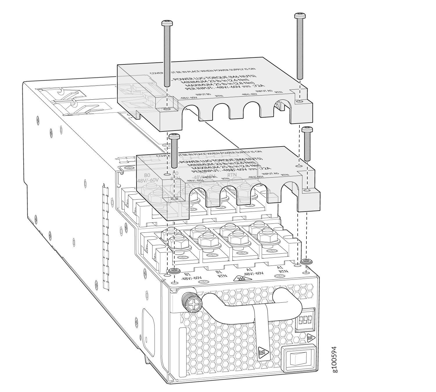
Remove the plastic cable cover from the power input terminals by using the
Phillips (+) screwdriver, number 2, to loosen the screws (see Figure 68).
Figure 68: Removing the Plastic Cable Cover on a JNP10K-PWR-DC2 Power Supply
-
Install heat-shrink tubing insulation around the power cables.
To install heat-shrink tubing:
-
Slide the tubing over the portion of the cable where it is attached to the lug barrel. Ensure that tubing covers the end of the wire and the barrel of the lug attached to it.
-
Shrink the tubing with a heat gun. Ensure that you heat all sides of the tubing evenly so that it shrinks around the cable tightly.
Figure 69 shows the steps to install heat-shrink tubing.
Note:Do not overheat the tubing.
Figure 69: How to Install Heat-Shrink Tubing
-
-
Install each power cable lug on the DC power input terminal, securing it with
the nut (see Figure 70). Apply between 24 in.-lb (2.7 N-m) and 25 in.-lb (2.8 N-m) of torque to each
nut. (Use the 13/32 in. [10 mm] nut driver or socket wrench.)
-
Secure each positive (+) DC source power cable lug to the RTN (return) DC power input terminal.
-
Secure each negative (–) DC source power cable lug to the –48V (input) DC power input terminal.
Each power supply has two independent sets of DC power input terminals (INPUT 1: RTN –48V/–60V: and INPUT 2: : RTN –48V/–60V). For feed redundancy, each power supply must be powered by dedicated power feeds derived from feed INPUT 1 and feed INPUT 2. This configuration provides the commonly deployed INPUT 1 / INPUT 2 feed redundancy for the router. There is basic insulation between the inputs and the chassis ground. Also, there is basic insulation between RTN input feeds.
Figure 70: Connecting the DC Power Supply Cables to a JNP10K-PWR-DC2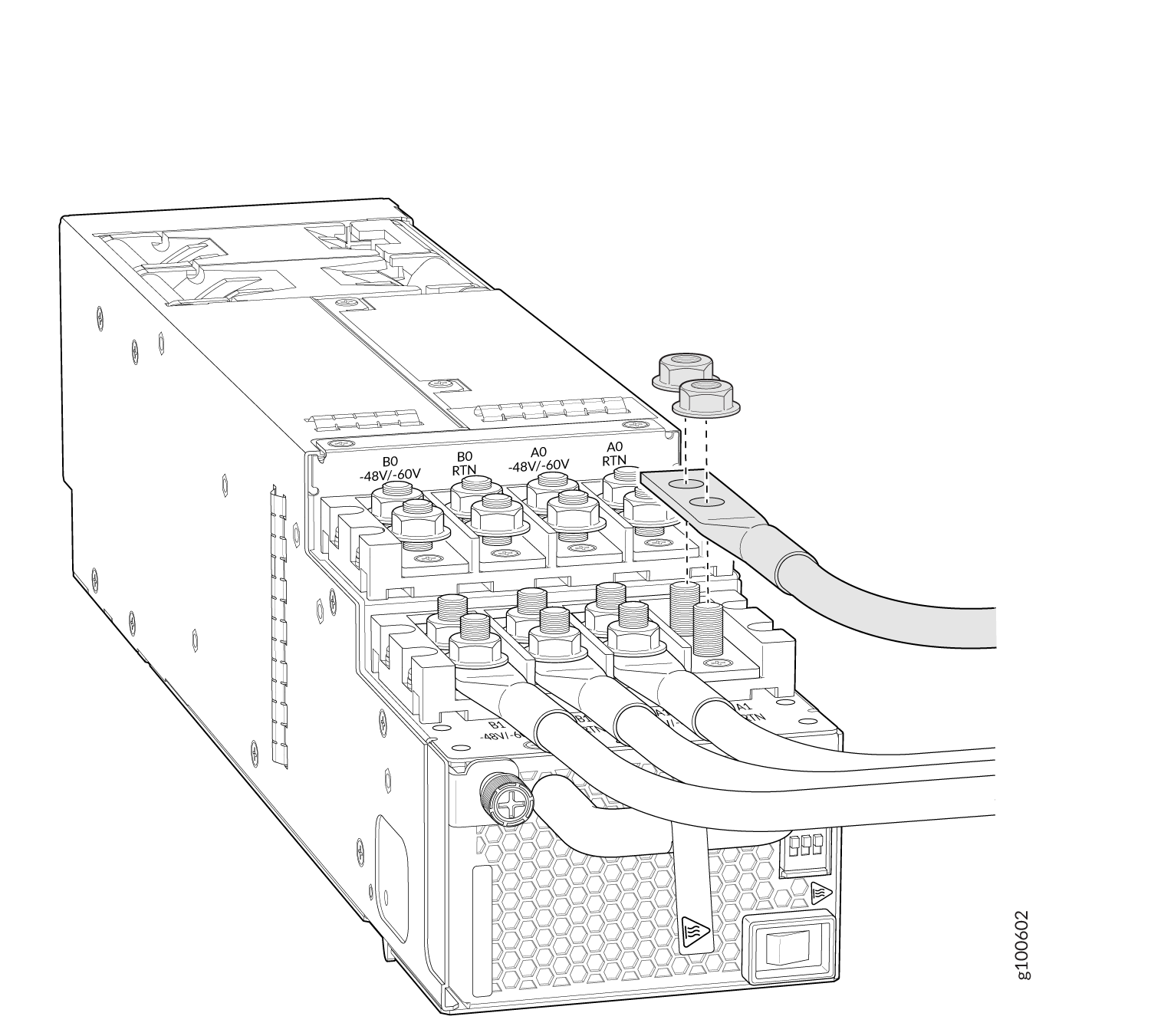
-
-
If the power supply slot on the chassis has a cover panel on it, insert your
thumb and forefinger into the finger holes, squeeze, and pull the cover out of the
slot. Save the cover panel for later use (see Figure 71
and Figure 72).
Figure 71: Removing the Power Supply Cover Panel on an MX10008
Figure 72: Removing the Power Supply Cover Panel on an MX10016
-
Tighten the captive screw by turning it clockwise by using the
Phillips (+) screwdriver, number 1. When the screw is completely tight, the latch
locks into the router chassis.
Figure 73: Installing a JNP10K-PWR-DC2 in an MX10008
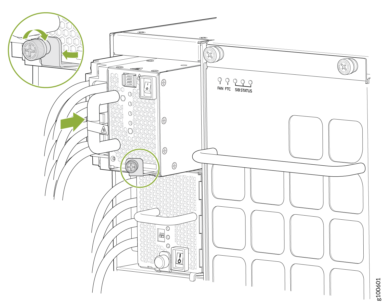 Figure 74: Installing a JNP10K-PWR-DC2 in an MX10016
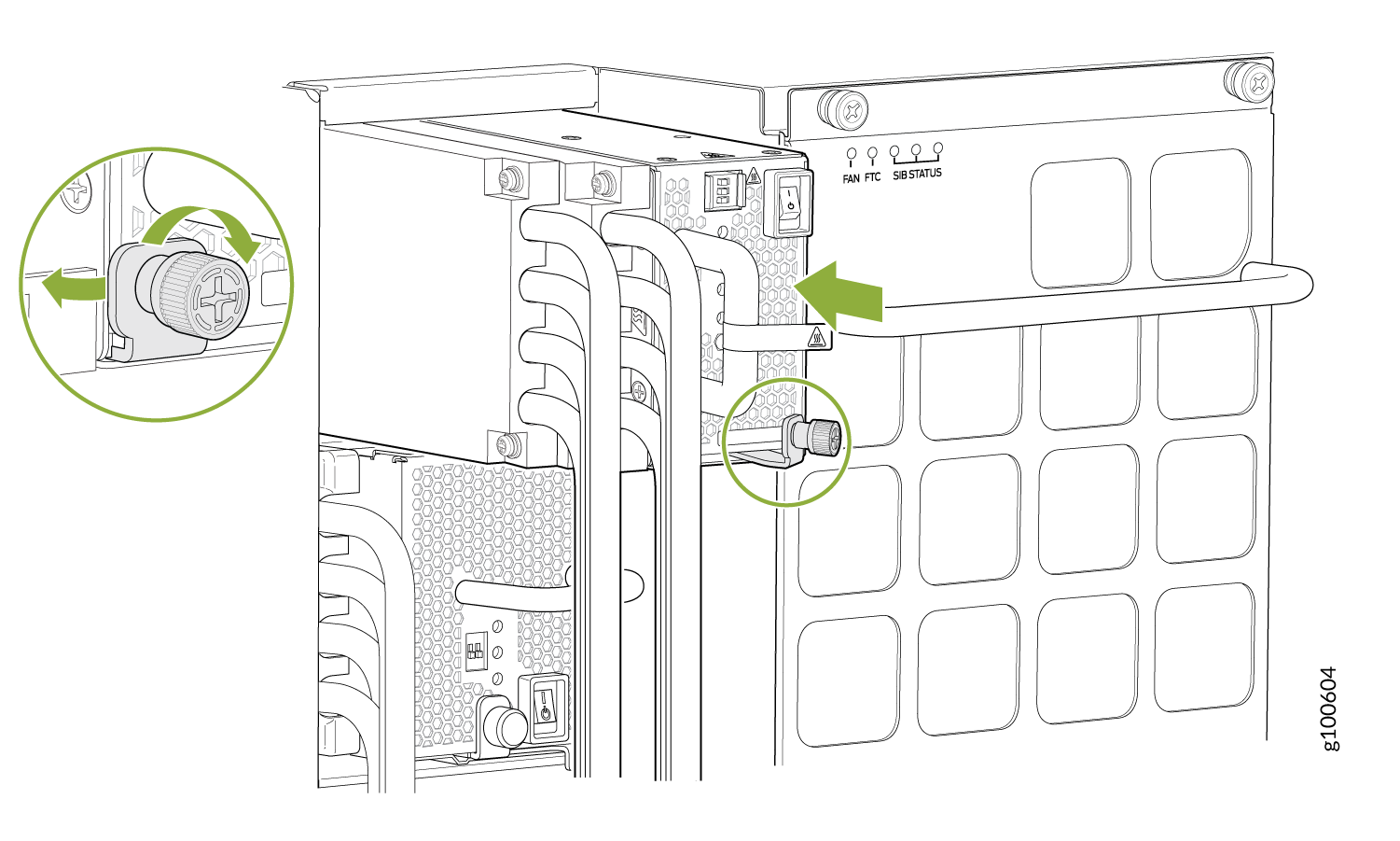
-
Route INP1 cables to a power source and INP2 to another power source. The
JNP10K-PWR-DC shares power, so if power dips on one input, the power supply is
able to load balance internally. See Figure 75 and Figure 76.
Figure 75: Proper Load Balancing for JNP10k-PWR-DC2 Power Cables on MX10008
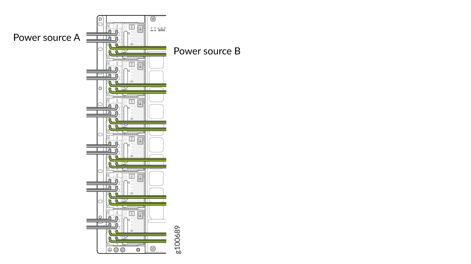 Figure 76: Proper Load Balancing for JNP10K-PWR-DC2 Power Cables on MX100016
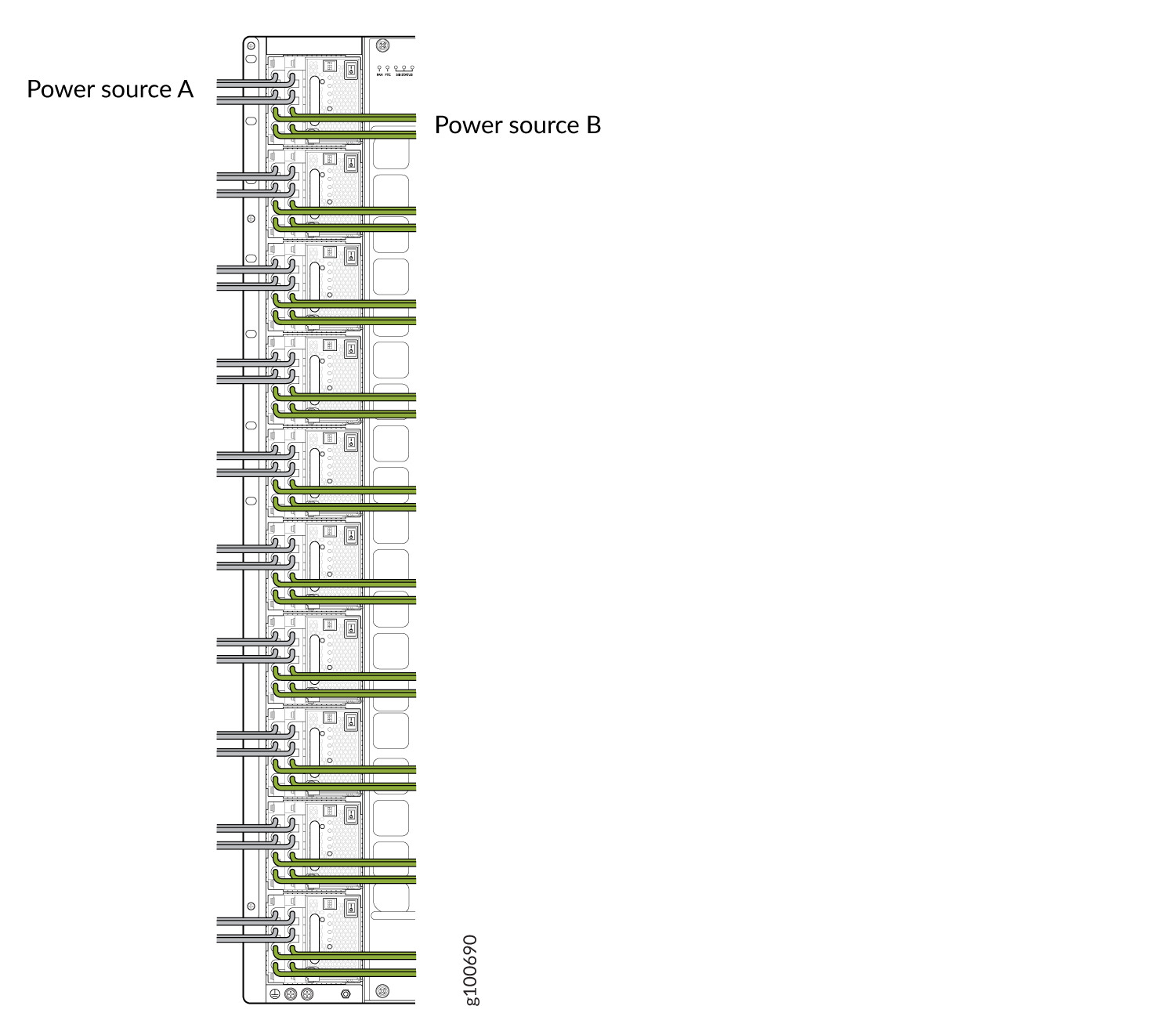 Warning:
Ensure that the power cords do not block access to router components or drape where people can trip on them.
-
Set the three dip switches to select the inputs and confirm whether the power
supply is running at 2200 W, 2750 W, 4400 W, or 5500 W. See Table 4 and Figure 77.
Set both enable routers to the on position when using both source inputs. When not using source redundancy, set the unused source to the O (off) position. The LED turns red and indicates an error if a source input is not in use and the enable router is | (on).
Table 4: Setting the JNP10K-PWR-DC2 Dip Switches Switch
State
Field
1
On
IP0 is present
Off
IP0 is not present
2
On
IP1 is present
Off
IP1 is not present
3
On
Enabled for 80 A feed; 2750-W for a single feed, 5500-W for dual feeds
Off
Enabled for 60 A feed; 2200-W for a single feed, 4400-W for dual feeds
Figure 77: Setting the Enable Routers for the Power Source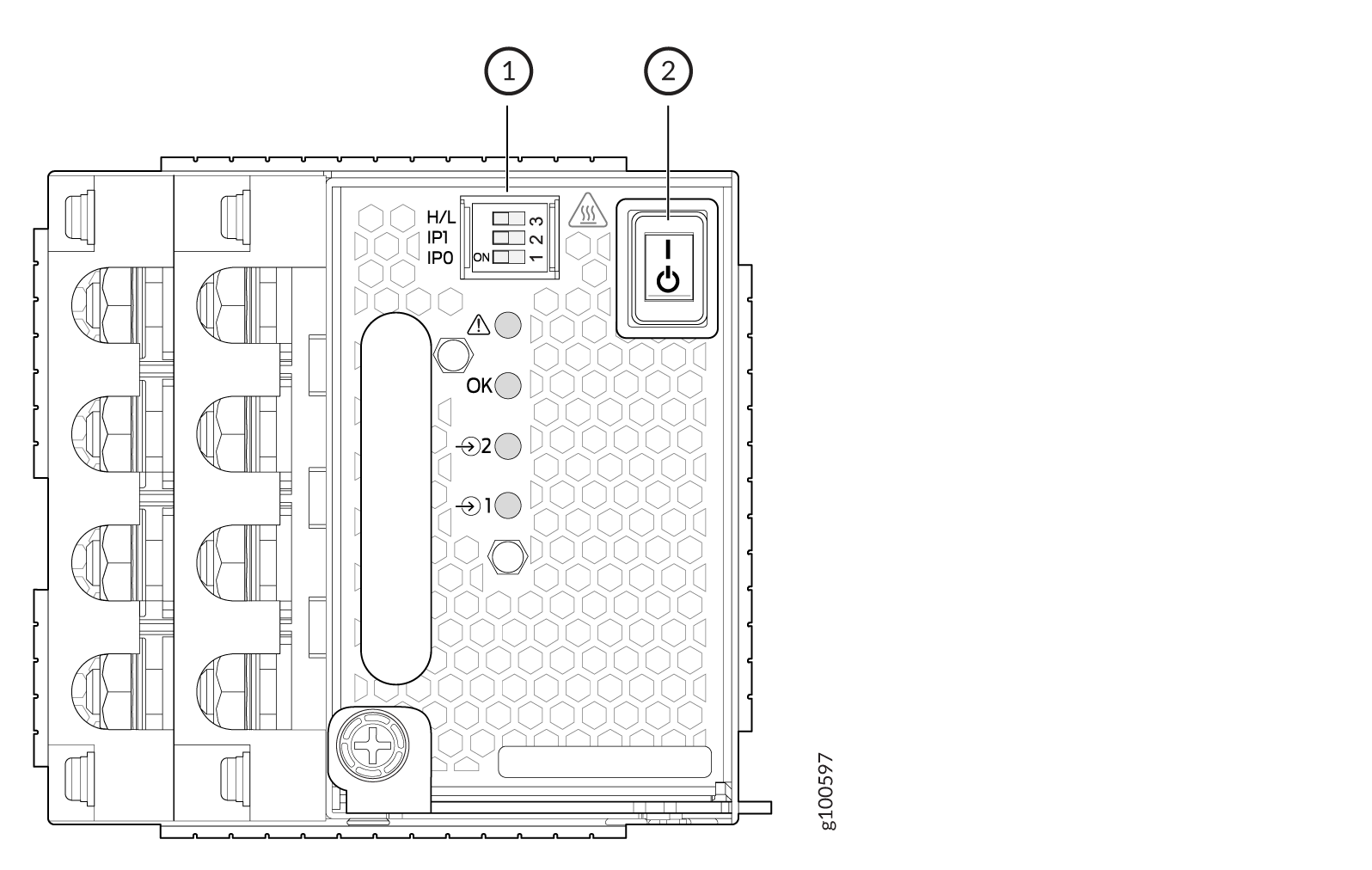 1—
1—Dip switches
2—Power switch, on (|) and standby (O)
How to Remove a JNP10K-PWR-DC3 Power Supply
Before you remove a DC power supply from the router:
-
Review how to prevent ESD damage. See Prevention of Electrostatic Discharge Damage.
-
Ensure that the following parts and tools are available before you remove a JNP10K-PWR-DC3 power supply:
-
Heat-protective gloves that can withstand temperatures of 158 °F to 176 °F (70 °C through 80 °C)
-
Electrostatic discharge (ESD) grounding strap
-
Phillips (+) screwdriver, numbers 1 and 2
-
13/32 in. (10 mm) nut driver or socket wrench
-
Replacement power supply or a cover for the power supply slot
-
A working JNP10K-PWR-DC3 power supply can reach temperatures of 158 °F through 176
°F (70 °C through 80 °C) when equipment is on. In order to avoid injury, do not
touch a running power supply with your bare hands.
Before you remove a power supply, ensure that you have power supplies sufficient to power the router left in the chassis. See Calculate Power Requirements for an MX10008 Router.
Do not leave the power supply slot empty for a long time while the router is operational. Either replace the power supply promptly or install an Active Blank Power Module (ABPM) over the empty slot.
To remove a JNP10K-PWR-DC3 power supply from an MX10008 router:
-
Wrap and fasten one end of the ESD grounding strap around your bare wrist and
connect the other end of the strap to an ESD point on the chassis. An ESD point is
located next to the protective earthing terminal and below
PSU 5 on the rear of the MX10008 (see Figure 78).
Figure 78: ESD Point on the Rear of the MX10008
 1—
1—ESD point
-
Unscrew the captive screw counterclockwise using the Phillips (+) screwdriver,
number 1. See Figure 79.
Figure 79: Remove a JNP10K-PWR-DC3 Power Supply from an MX10008
 1—
1—Loosen captive screw (counterclockwise)
2—Release latch
-
Rotate the captive screw away from the faceplate of the power supply to release
the latch.
Note:
Ensure that the ejector is fully open to prevent damaging the chassis. See Figure 80.
Figure 80: Open Power Supply Ejector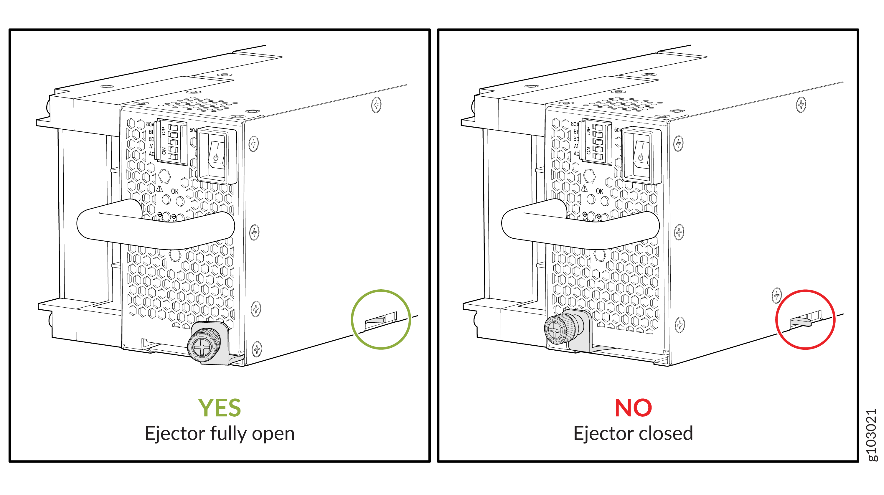
How to Install a JNP10K-PWR-DC3 Power Supply
Before you install a JNP10K-PWR-DC3 power supply in the chassis:
-
Ensure that you follow all safety warnings and cautions.
Note:Before performing DC power procedures, ensure that power is removed from the DC circuit. To ensure that all power is off, locate the circuit breaker on the panel board that services the DC circuit, switch the circuit breaker to the off (O) position, and tape the switch handle of the circuit breaker in the off position.
Note:Protect yourself from severe burns by wearing heat-protective gloves when removing a working JNP10K-PWR-DC3 power supply from the chassis. JNP10K-PWR-DC3 power supplies can reach temperatures from 158° F to 176° F (70° C to 80° C) when equipment is on.
Note:Before you connect power to the router, a licensed electrician must attach a cable lug to the grounding and power cables that you supply. A cable with an incorrectly attached lug can damage the router (for example, by causing a short circuit).
Note:Use the same type of power supply in all slots. Do not mix AC and DC power supplies in a production chassis.
Note:To meet safety and electromagnetic interference (EMI) requirements and to ensure proper operation, you must connect the MX10008 routers to earth ground before you connect them to power. For installations that require a separate grounding conductor to the chassis, use the protective earthing terminal on the router chassis to connect to earth ground. For instructions on connecting an MX10008 router to ground using a separate grounding conductor, see Connect the MX10008 to Earth Ground.
Note:The battery returns of the JNP10K-PWR-DC3 power supply must be connected as an isolated DC return (DC-I).
-
Review how to prevent ESD damage. See Prevention of Electrostatic Discharge Damage.
-
Ensure that you have the following parts and tools available before you install a DC power supply:
-
Electrostatic discharge (ESD) grounding strap
-
The provided terminal lugs for the JNP10K-PWR-DC3 (Panduit LCD4-14A-L for straight lugs, LCD-4-14AH-L for 45° lugs, or equivalent) and sized for 4 AWG (21.1 mm²) power source cables. We recommend that you install heat-shrink tubing insulation around the crimpled section of the power cables and lugs (see step 9).
-
13/32 in. (10 mm) nut driver or socket wrench
-
Phillips (+) screwdrivers, numbers 1 and 2
-
Multimeter
-
The JNP10K-PWR-DC3 power supply in an MX10008 chassis is a hot-removable and hot-insertable field-replaceable unit (FRU). You can install up to three power supplies in the rear along the left side of the chassis.
To install a JNP10K-PWR-DC3 power supply in an MX10008:
-
Wrap and fasten one end of the ESD grounding strap around your bare wrist and
connect the other end of the strap to an ESD point on the chassis. An ESD point is
located next to the protective earthing terminal and below PSU
2 on the rear of the MX10008 (see Figure 81).
Figure 81: ESD Point on the Rear of the MX10008
 1—
1—ESD point
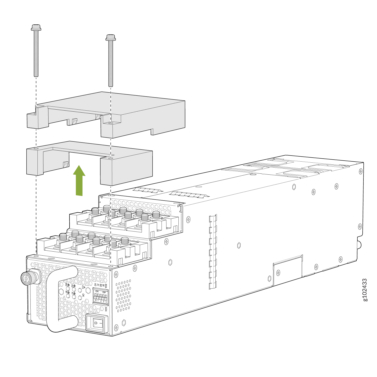
-
Remove the plastic cable cover from the power input terminals by using the
Phillips (+) screwdriver, number 2 to loosen the screws (see Figure 82).
Figure 82: Remove the Plastic Cable Cover on a JNP10K-PWR-DC3 Power Supply
-
Verify that the DC power cables are labeled correctly before making connections
to the power supply. In a typical power distribution scheme where the return is
connected to chassis ground at the battery plant, you can use a multimeter to
verify the resistance of the -48 V and RTN DC cables to the chassis
ground.
-
The cable with very high resistance (indicating an open circuit) to chassis ground is negative (-) and will be installed on the -48 V (input) DC power input terminal.
-
The cable with very low resistance (indicating a closed circuit) to chassis ground is positive (+) and will be installed on the RTN (return) DC power input terminal.
The JNP10K-PWR-DC3 power supply is the equivalent of four power supplies in a single housing. Each JNP10K-PWR-DC3 has four independent sets of DC power input terminals:
-
Input A0: RTN -48 V/-60 V
-
Input B0: RTN -48 V/-60 V
-
Input A1: RTN -48 V/-60 V
-
Input B1: RTN -48 V/-60 V
We recommend source redundancy (source A and source B) to all inputs to ensure reliability of the system. If two power sources are not available, then use two feeds from the same source to provide power distribution reliability. Two feeds mean two independent power distribution routes from the source to the system. See Figure 83.
Figure 83: JNP10K-PWR-DC3 Input Terminal Marking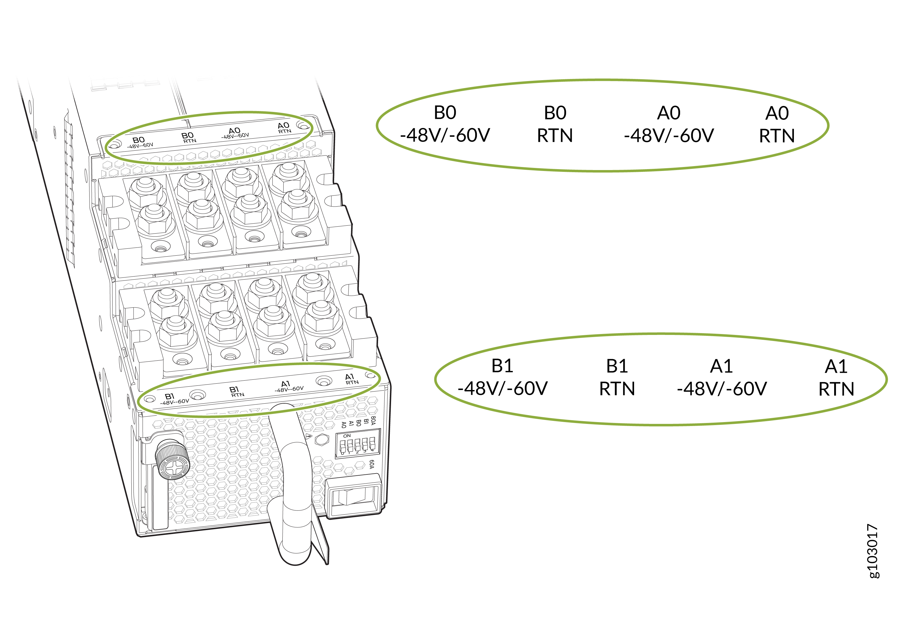 CAUTION:
You must ensure that power connections maintain proper polarity. The power source cables might be labeled (+) and (–) to indicate their polarity. There is no standard color coding for DC power cables.
-
-
Install heat-shrink tubing insulation around the power cables.
To install heat-shrink tubing:
-
Slide the tubing over the portion of the cable where it is attached to the lug barrel. Ensure that tubing covers the end of the wire and the barrel of the lug attached to it.
-
Shrink the tubing with a heat gun. Ensure that you heat all sides of the tubing evenly so that it shrinks around the cable tightly.
Figure 84 shows the steps to intall heat-shrink tubing.
Note: Do not overheat the tubing.Figure 84: How to Install Heat-Shrink Tubing
-
-
Install each power cable lug on the relevant DC power input terminal, securing
each cable lug with the nut (see Figure 85
and Figure 86). Apply between 23 lb-in.
(2.6 Nm) and 25 lb-in. (2.8 Nm) of torque to each nut. (Use the 13/32 in. (10 mm)
nut driver or socket wrench.)
-
Secure each positive (+) DC source power cable lug to the RTN (return) DC power input terminal.
-
Secure each negative (–) DC source power cable lug to the –48 V (input) DC power input terminal.
Figure 85: Connect the DC Power Source Cables to a JNP10K-PWR-DC3 Power Supply (INP-A1)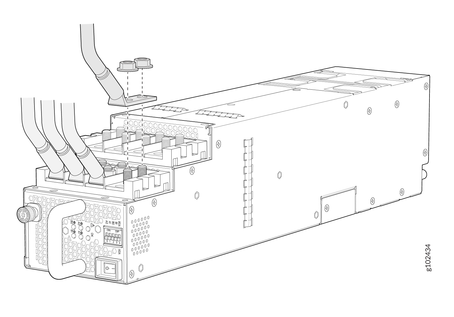 Figure 86: Connect the DC Power Source Cables to a JNP10K-PWR-DC2 Power Supply (INP-A0)
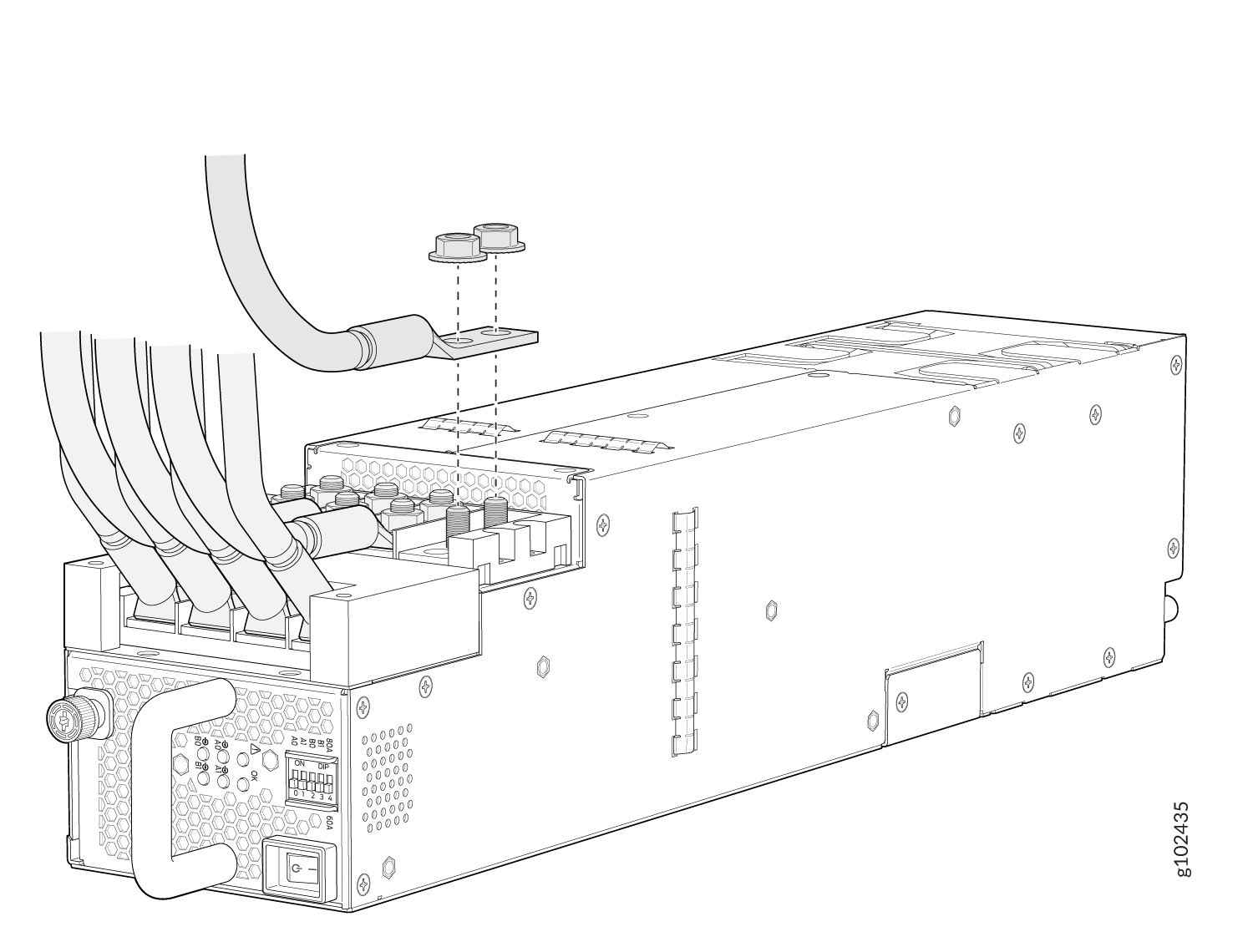
-
-
If the power supply slot on the chassis has a cover panel on it, insert your
thumb and forefinger into the finger holes, squeeze, and pull the cover out of the
slot. Save the cover panel for later use (see Figure 87).
Figure 87: Removing the Power Supply Cover Panel on an MX10008
-
Tighten the captive screw by turning it clockwise with the Phillips (+)
screwdriver, number 1. When the captive screw is completely tight, the latch locks
into the router chassis.
Figure 88: Install a JNP10K-PWR-DC3 in an MX10008
 1—
1—Lock latch
2—Tighten captive screw (clockwise)
-
Route INP0 cables to a power source and INP1 to another power source. The
JNP10K-PWR-DC3 load balances internally by sharing power when the power dips on
one input.
Figure 89: Proper Load Balancing for JNP10K-PWR-DC3 Power Cables on MX10008
 Warning:
Ensure that the power cords do not block access to router components or drape where people can trip on them.
-
Set the five DIP switches to indicate the number of input sources and to
indicate high or low power (see Table 5
and Figure 90).
Set the four enable switches to the on position when using both source inputs. Set the unused source to the off position when source redundancy is not in use. The LED turns red and indicates an error if a source input is not in use and the enable switch is on.
Table 5: Set the JNP10K-PWR-DC3 DIP Switches Switch
State
Description
0
On
A0 is present.
Off
A0 is not present.
1
On
A1 is present.
Off
A1 is not present.
2
On
B0 is present.
Off
B0 is not present.
3
On
B1 is present.
Off
B1 is not present.
4
On
Enabled for high-power (80 A) feed.
Off
Enabled for low-power (60 A) feed.
Figure 90: Setting the DIP Switches for the Power Source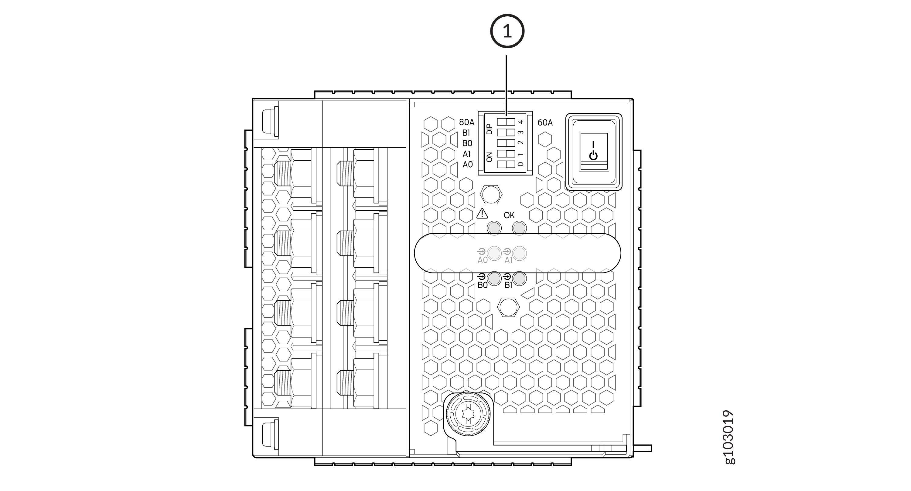 1—
1—DIP Switches
For more information on DIP switch settings, see Table 5.