ON THIS PAGE
MX10008 Power System
The MX10008 modular routers support AC, DC, high-voltage alternating current (HVAC) and high-voltage direct current (HVDC) by offering the following power supplies:
-
JNP10K-PWR-AC
-
JNP10K-PWR-AC2
-
JNP10K-PWR-AC3
-
JNP10K-PWR-DC
-
JNP10K-PWR-DC2
-
JNP10K-PWR-DC3
-
JNP10K-PWR-AC3H (HVAC/HVDC)
All of the power supplies are hot-insertable and hot-removable, field-replaceable units (FRUs). You can install up to six power supplies in an MX10008 router in the slots labeled PEM 0 through PEM 5 (top to bottom) located in the rear of the chassis. You can install the power supplies in any slot.
The JNP10K-PWR-AC2 and JNP10K-PWR-DC2 power supplies share power. The JNP10K-PWR-AC and JNP10K-PWR-DC power supplies do not share power.
The JNP10K-PWR-AC2 and JNP10K-PWR-AC3 can share power proportionally in a mixed configuration, only when you are upgrading to JNP10K-PWR-AC3.
The power supplies support standard or enhanced power bus. To determine whether your system has the standard power bus or the enhanced power bus, see MX10008 Status Panel LEDs. Table 1 provides the specifications for these different power supplies.
|
JNP10K-PWR-AC |
JNP10K-PWR-AC2 |
JNP10K-PWR-AC3 |
JNP10K-PWR-DC |
JNP10K-PWR-DC2 |
JNP10K-PWR-DC3 |
JNP10K-PWR-AC3H |
|
|---|---|---|---|---|---|---|---|
|
Maximum output power |
2700 W |
5000 W or 5500 W when set for high power (30-A); 3000 W when set for low power (20-A) |
|
2500 W |
5500 W when set for high power (80-A) or 4400 W when set for low power (60-A) |
|
|
|
Inputs |
2 (INP1, INP2) |
2 (INP1, INP2) |
4 (INP A0, INP A1, INP B0, INP B1) |
2 (INP1, INP2) |
4 (INPUT 1, INPUT 2) |
4 (INP A0, INP A1, INP B0, INP B1) |
4 (INP A0, INP A1, INP B0, INP B1) |
|
Compatible power bus |
Standard or enhanced |
Standard or enhanced |
Standard or enhanced |
Standard or enhanced |
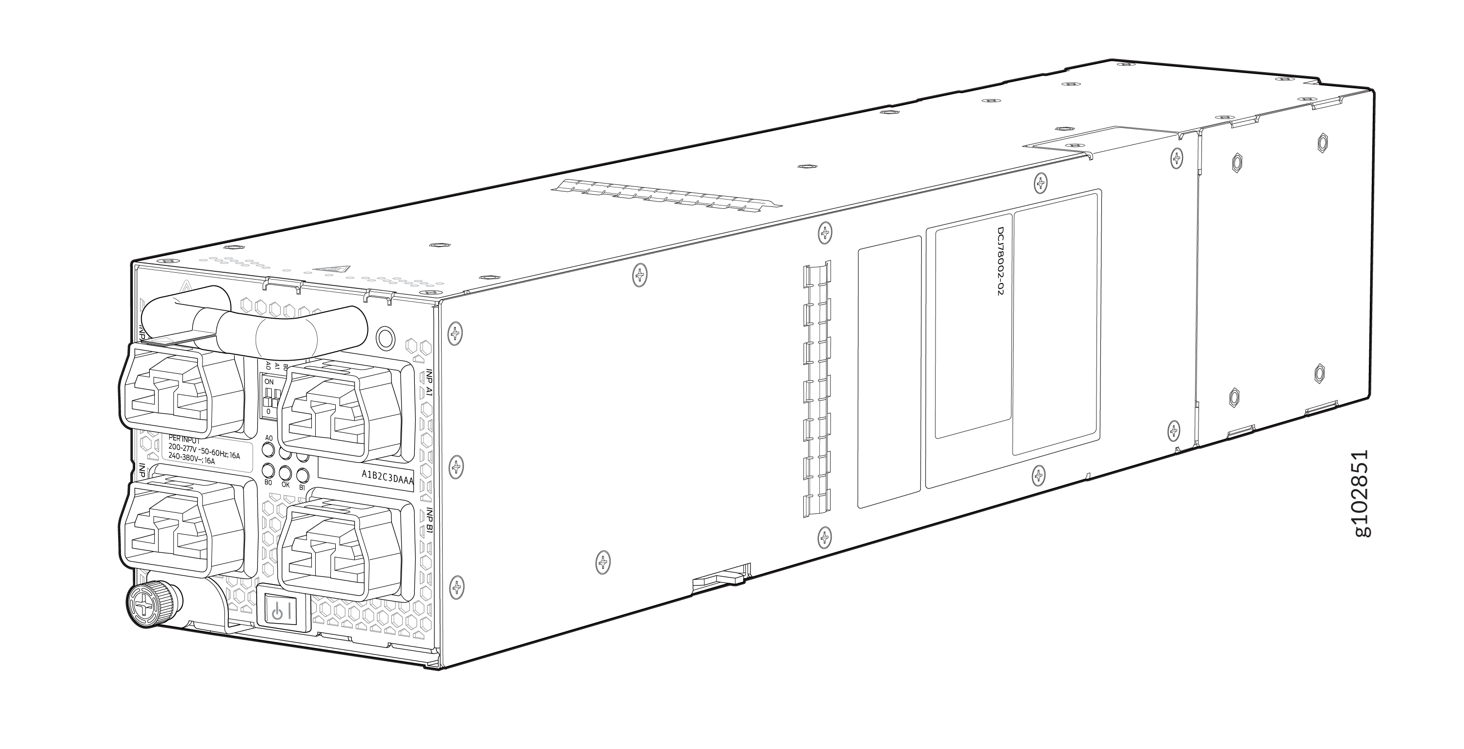
JNP10K-PWR-AC3 Power Supply
The JNP10K-PWR-AC3 power supply is a high-capacity model that is designed to support AC systems in a 15-A and 20-A mode; see Figure 1.
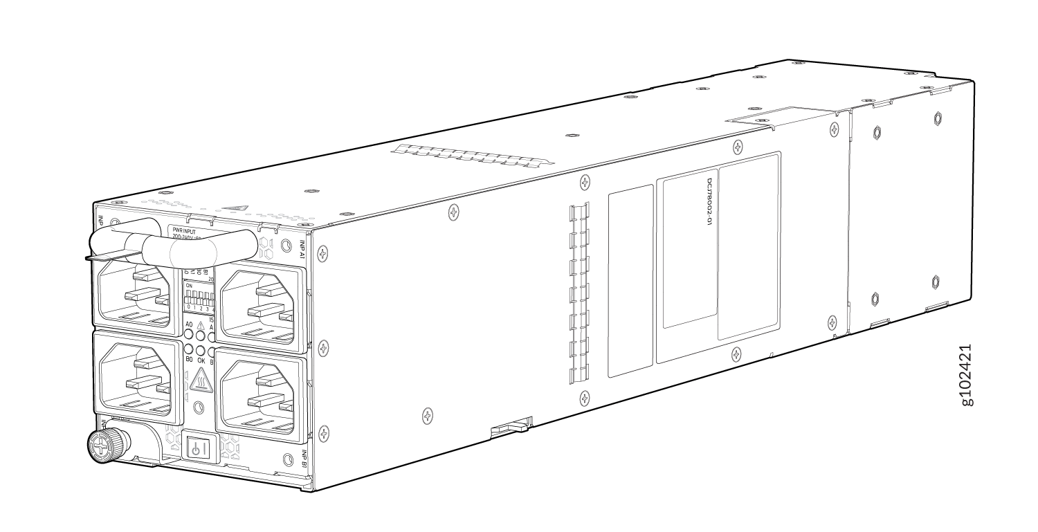
Input—The power supply takes four single-phase AC (180-264 VAC) inputs (A0, A1, B0, and B1) at either 20 A or 15 A and provides a DC output of 12.3V. The input receptacle on the AC power supply unit (PSU) is IEC 320-C22. The mating connector on the power cord is IEC 320-C21.
Output—The power supply provides DC output of 12.3V at:
- 7800 W (20-A input) with three or four active feeds, or
- 6000 W (20-A input) with two active feeds (either A0 and A1 or B0 and B1), or
- 3000 W (20-A input) with single active feed.
-
7800 W (15-A input) with four active feeds, or
-
6900 W (15-A input) with three active feeds, or
-
4600 W (15-A input) with two active feeds, or
-
2300 W (15-A input) with single active feed.
-
The operating input voltage range is 180 to 264 VAC for AC systems. The DC output is 12.3 VDC.
-
The number of power feeds and whether the power supplies provide high-output (20-A) or low-output (15-A) power are configured using a set of dual inline package (DIP) switches on the faceplate of the power supply. If one power supply in the chassis is set to low power, the power budget for the chassis is reduced to low power, regardless of their DIP switch settings or the output results in the CLI. This design safeguards against accidentally setting the power supply to 20 A in a facility that can provide only 15 A and tripping the facility circuit breaker. We recommend that you don’t mix DIP switch settings in your system. See Table 2 for information about the input and output voltages when you use the DIP switches.
-
The JNP10K-PWR-AC3 power supply has an ENABLE switch on the front panel to enable/disable the main 12.3 VDC output and +5.0 V_BIAS standby output as well. If the switch is in DISABLE position, the front-end PFC will be disabled to minimize power consumption. This switch has the highest priority over any other shutdown method.
-
The Power Factor Correction (PFC) is PF 0.98 kW minimum at full load. The maximum inrush current is 50 A for the active feed.
JNP10K-PWR-BLN3 or Active Blank
Juniper Networks offers an Active Blank Power Module (ABPM), JNP10K-PWR-BLN3. This helps in airflow and cooling in the chassis.
A minimum of one JNP10K-PWR-AC3 power supply unit (PSU) must be present in the router chassis.
The JNP10K-PWR-AC3 power supply has internal fans that contribute to chassis cooling. Three PSUs or two PSUs along with a ABPM must be present in a running chassis to have the adequate airflow. While the minimum power supplies are required to be present in the chassis, they all need not be necessarily connected to power source. If a power supply is installed in a slot but not connected to a power source, it draws power from the chassis to power the internal fans in the power supplies.
Extreme burn danger—The JNP10K-PWR-AC3 can reach temperatures in the range of 158°F to 176°F (70°C to 80°C) under running conditions.
The router is pluggable type A equipment installed in a restricted-access location. It has a separate protective earthing terminal on the chassis that must be connected to earth ground permanently to ground the chassis adequately and protect the operator from electrical hazards.
Before you begin installing the router, ensure that a licensed electrician has attached an appropriate grounding lug to the grounding cable that you supply. Using a grounding cable with an incorrectly attached lug can damage the router.
Use a 2-pole circuit breaker rated at 25 A in the building installation and the system, or as per local electrical code.
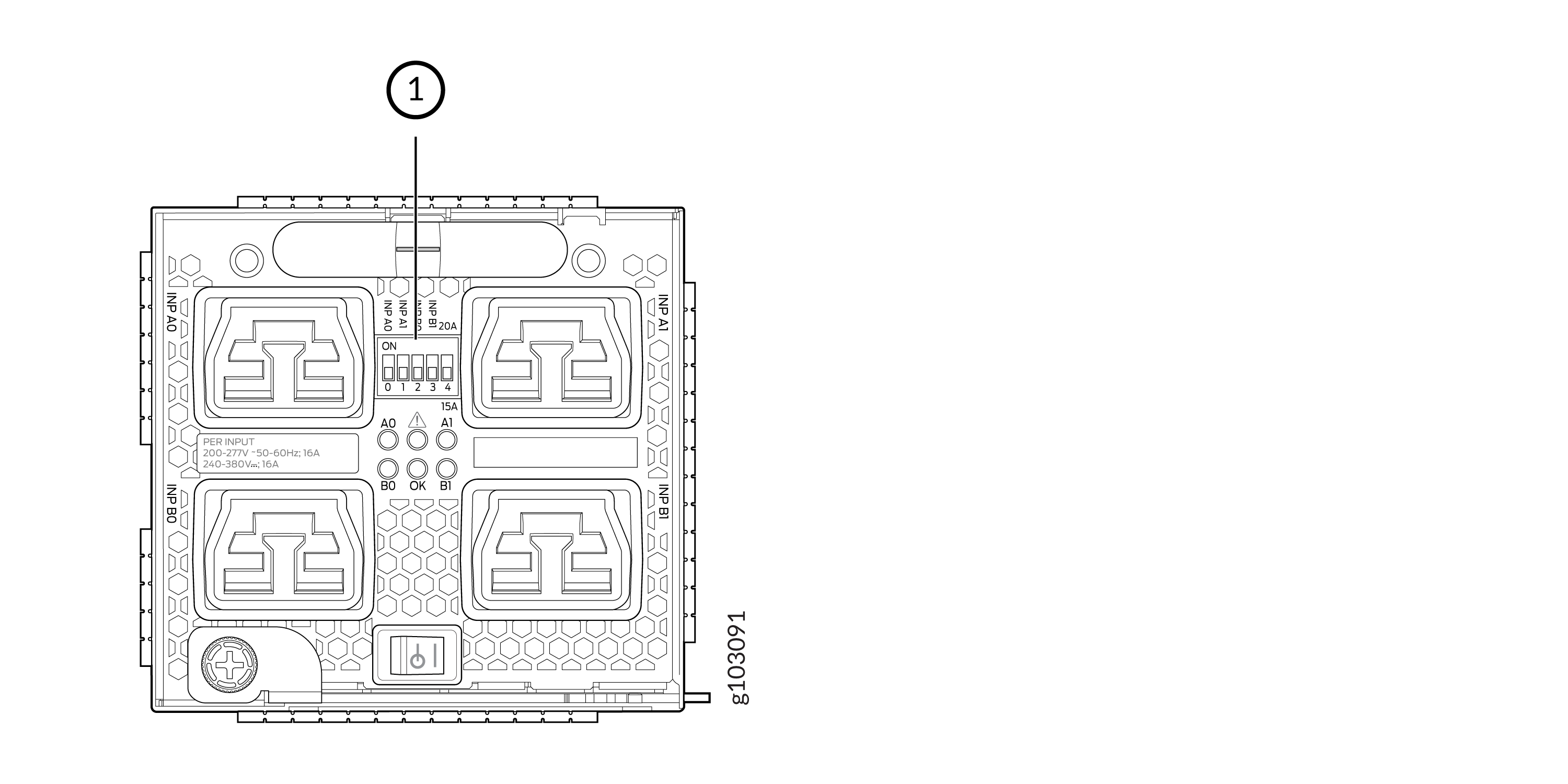
The JNP10K-PWR-AC3 Power Supplies have five dual position DIP switches (INP-A0, INP-A1, INP-B0, INP-B1, and DIP4) that are accessible from the front panel. DIP4 is the fifth DIP switch, which is used to indicate whether 20A or 15A input source is connected. See Figure 2 and Table 2 to know the layout of the DIP switches and the power output when the DIP switches are set in different combinations.
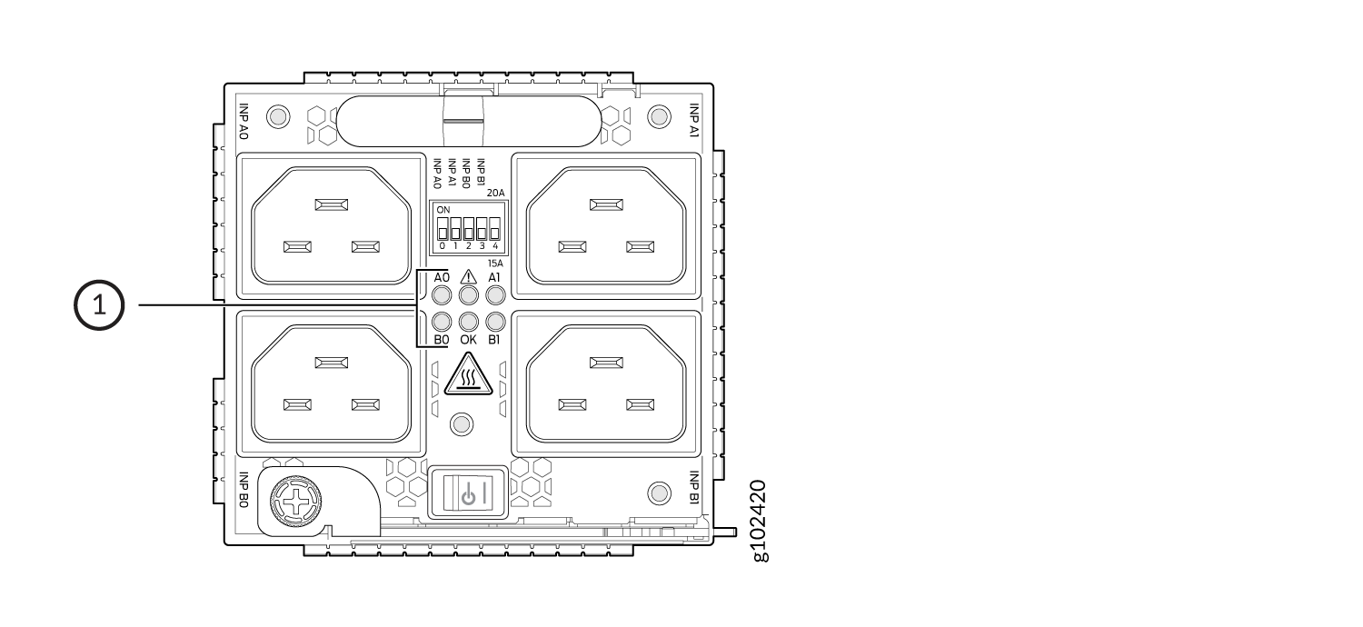
1—LEDs corresponding to the DIP switches above it.
|
INP-A0 (Switch 0) |
INP-A1 (Switch 1) |
INP-B0 (Switch 2) |
INP-B1 (Switch 3) |
Switch 4 (High Input 20 A/Low Input 15 A) |
Output Power |
|---|---|---|---|---|---|
|
15-A |
|||||
|
Off |
Off |
Off |
On |
Off (15 A) |
2300 W |
|
Off |
Off |
On |
Off |
Off (15 A) |
2300 W |
|
Off |
Off |
On |
On |
Off (15 A) |
4600 W |
|
Off |
On |
Off |
Off |
Off (15 A) |
2300 W |
|
Off |
On |
Off |
On |
Off (15 A) |
4600 W |
|
Off |
On |
On |
On |
Off (15 A) |
6900 W |
|
Off |
On |
On |
Off |
Off (15 A) |
4600 W |
|
On |
Off |
Off |
Off |
Off (15 A) |
2300 W |
|
On |
Off |
Off |
On |
Off (15 A) |
4600 W |
|
On |
Off |
On |
Off |
Off (15 A) |
4600 W |
|
On |
Off |
On |
On |
Off (15 A) |
6900 W |
|
On |
On |
Off |
Off |
Off (15 A) |
4600 W |
|
On |
On |
Off |
On |
Off (15 A) |
6900 W |
|
On |
On |
On |
Off |
Off (15 A) |
6900 W |
|
On |
On |
On |
On |
Off (15 A) |
7800 W |
|
20-A |
|||||
|
Off |
Off |
Off |
On |
On (20 A) |
3000 W |
|
Off |
Off |
On |
Off |
On (20 A) |
3000 W |
|
Off |
Off |
On |
On |
On (20 A) |
6000 W |
|
Off |
On |
Off |
Off |
On (20 A) |
3000 W |
|
Off |
On |
Off |
On |
On (20 A) |
6000 W |
|
Off |
On |
On |
Off |
On (20 A) |
6000 W |
|
Off |
On |
On |
On |
On (20 A) |
7800 W |
|
On |
Off |
Off |
Off |
On (20 A) |
3000 W |
|
On |
Off |
Off |
On |
On (20 A) |
6000 W |
|
On |
Off |
On |
Off |
On (20 A) |
6000 W |
|
On |
Off |
On |
On |
On (20 A) |
7800 W |
|
On |
On |
Off |
Off |
On (20 A) |
6000 W |
|
On |
On |
Off |
On |
On (20 A) |
7800 W |
|
On |
On |
On |
Off |
On (20 A) |
7800 W |
|
On |
On |
On |
On |
On (20 A) |
7800 W |
It is important to connect the input feeds of the JNP10K-PWR-AC3 power supply to AC mains before powering-on the router.
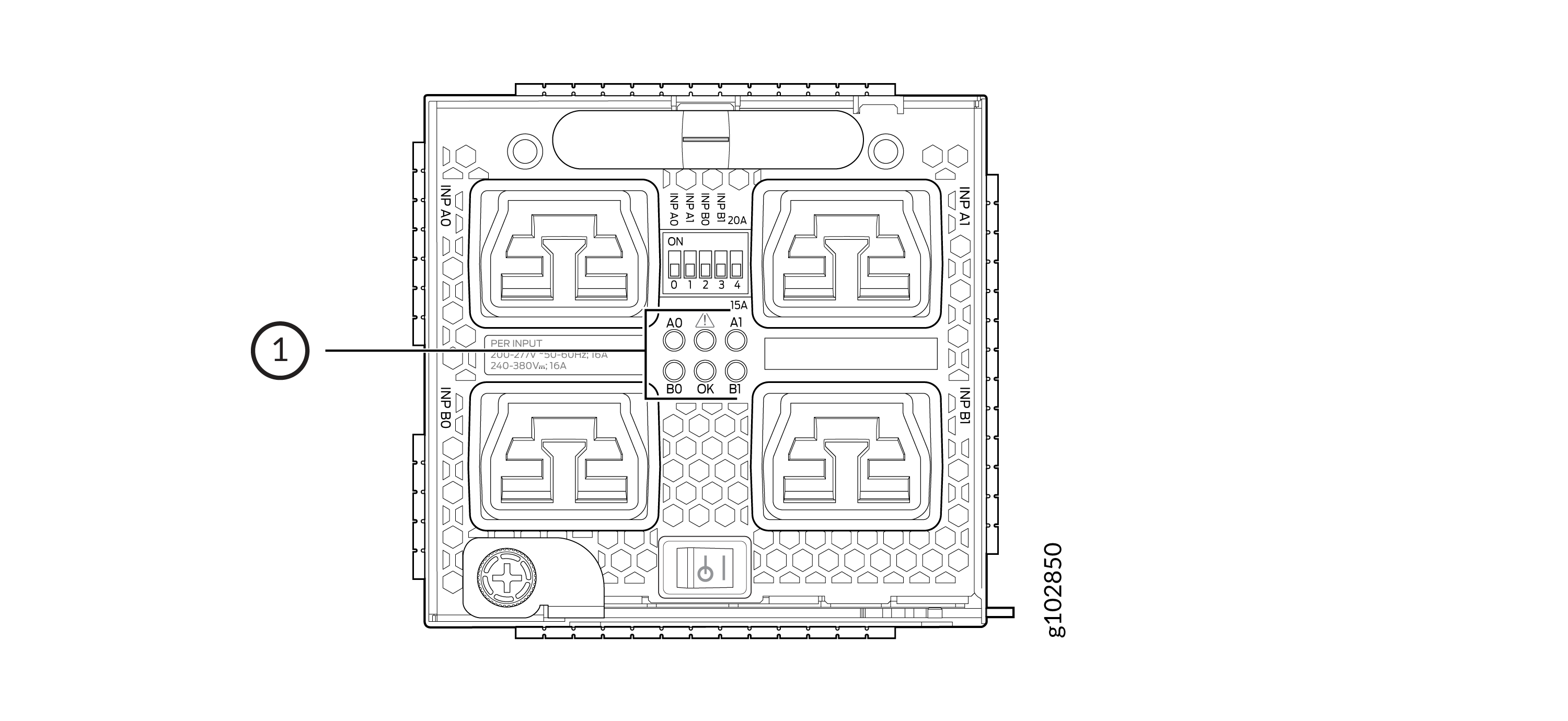
JNP10K-PWR-AC3 Power Supply LEDs
The JNP10K-PWR-AC3 power supply has six LEDs on its faceplate: !, OK, A0, A1, B0, and B1. The numbered LEDs correspond to the four inputs (INP-A0, INP-A1, INP-B0, and INP-B1). Additionally, there are two more LEDs OK (Power OK) and !(Fault). These LEDs display information about the status of the power supply. See Figure 3.
1—LEDs on the JNP10K-PWR-AC3 Power Supply denoting:
-
! Fault
-
OK Power OK
-
A0 INP A0–Source input 1
-
A1 INP A1–Source input 2
-
B0 INP B0–Source input 3
-
B1 INP B1–Source input 4
Physical markings on the power supply are 1,
2, 3, and
4. These markings correspond to INP-A0, INP-A1,
INP-B0, and INP-B1 in the show chassis power output (see Table 3).
|
Physical Marking on JNP10K-PWR-AC3 |
show chassis power Command |
|---|---|
|
INP A0 |
INP-A0 |
|
INP A1 |
INP-A1 |
|
INP B0 |
INP-B0 |
|
INP B1 |
INP-B1 |
Table 4 describes the LEDs on a JNP10K-PWR-AC3 power supply, color on the LED, state, and its meaning.
|
LED |
Color |
State |
Description |
|---|---|---|---|
|
1 or ( |
Amber |
Solid |
One of the following:
|
|
Green |
Solid |
The power supply is functioning properly. |
|
|
2 or ( |
Amber |
Solid |
One of the following:
|
|
Green |
Solid |
The power supply is functioning properly. |
|
|
3 or ( |
Amber |
Solid |
One of the following:
|
|
Green |
Solid |
The power supply is functioning properly. |
|
|
4 or ( |
Amber |
Solid |
One of the following:
|
|
Green |
Solid |
The power supply is functioning properly. |
|
|
OK (Power OK) |
Green |
Solid |
The power supply is functioning properly. |
|
Amber |
Blinking |
The power supply output has detected a fault. |
|
|
Unlit |
Off |
The power supply is switched off. |
|
|
! (Fault) |
Red |
Solid |
The power supply has failed and must be replaced. |
|
Unlit |
Off |
The power supply is functioning normally. |
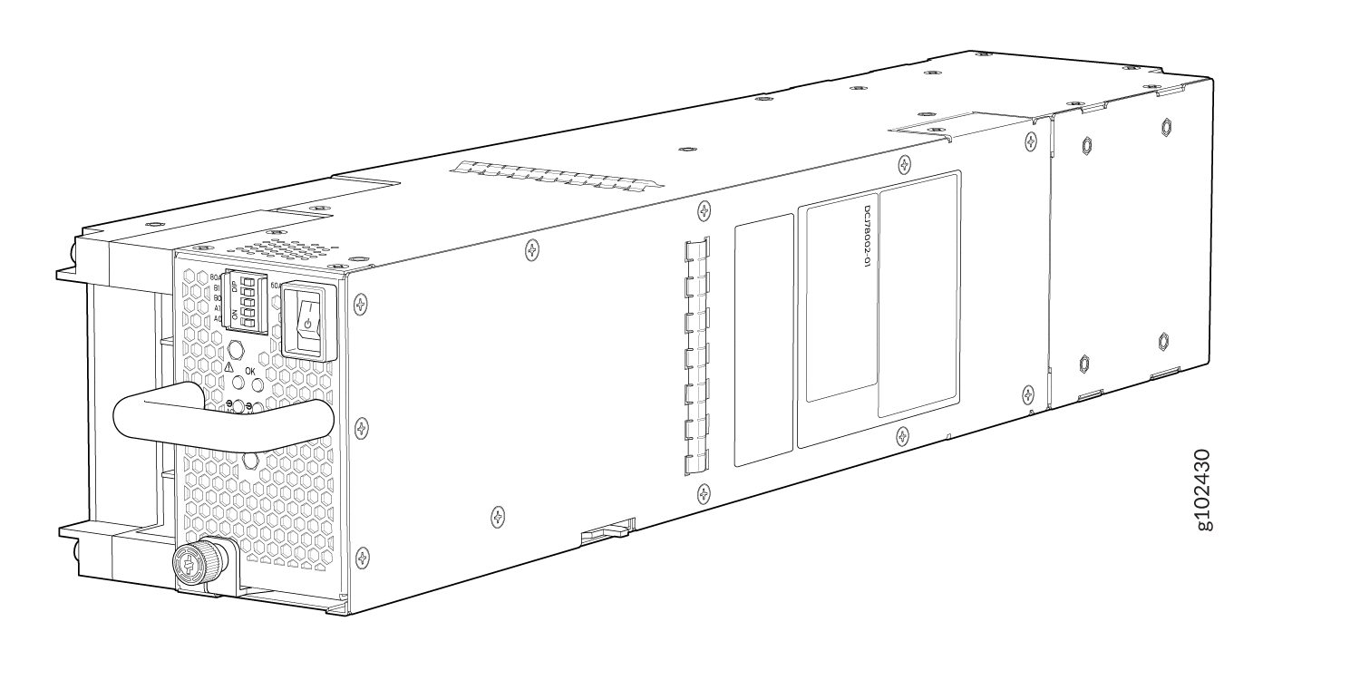
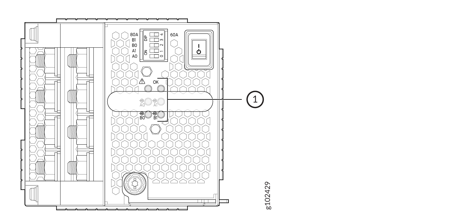
JNP10K-PWR-DC3 Power Supply
The JNP10K-PWR-DC3 power supply is a high-capacity model designed to support four power supplies in a single housing that accepts either 60 A or 80 A from four input power feeds.
The JNP10K-PWR-DC3 power supply has an ON/Standby switch on the front panel to enable or disable the main 12.3 VDC output and +5.0 V_BIAS standby output.
The number of power feeds and whether the power supplies provide high input of 80 A or low input of 60 A power are configured using the dual inline package (DIP) switches on the front panel of the power supply. The JNP10K-PWR-DC3 power supplies have five dual-position DIP switches. DIP0 through DIP3 switches (INP-A0, INP-A1, INP-B0, INP-B1) indicate whether the input is connected to the source. DIP4 (fifth DIP switch) indicates whether an 80 A or 60 A input source is connected. See Figure 5 for the layout of the DIP switches, and Table 5 for information on the power output when the DIP switches are set in different combinations.
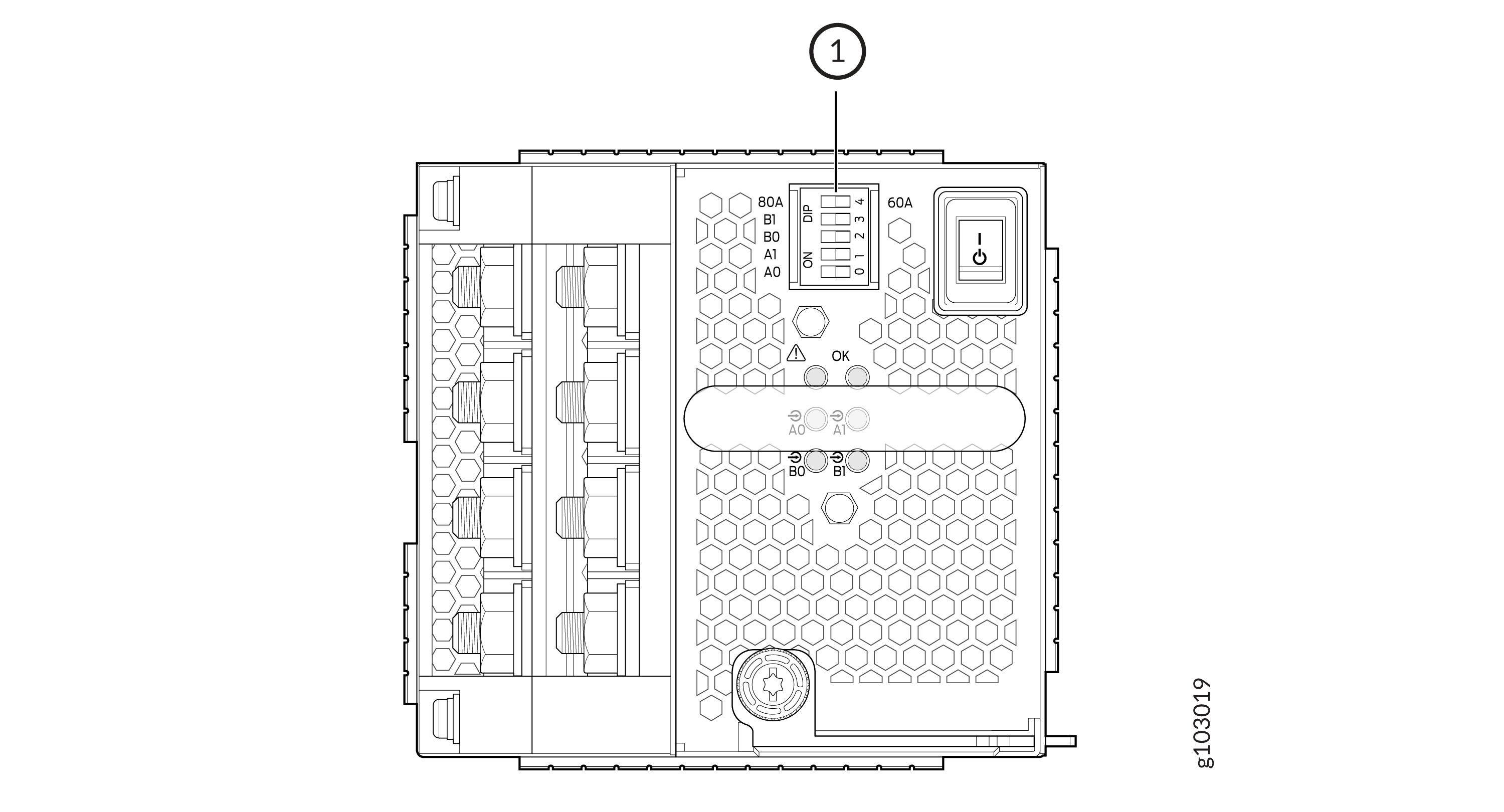
1 — DIP Switches |
|
INP-A0 (Switch 0) |
INP-A1 (Switch 1) |
INP-B0 (Switch 2) |
INP-B1 (Switch 3) |
Switch 4 (Low Input 60 A/ High Input 80 A) |
Output Power |
|---|---|---|---|---|---|
|
60 A |
|||||
|
Off |
Off |
Off |
On |
Off (60 A) |
2200 W |
|
Off |
Off |
On |
Off |
Off (60 A) |
2200 W |
|
Off |
Off |
On |
On |
Off (60 A) |
4400 W |
|
Off |
On |
Off |
Off |
Off (60 A) |
2200 W |
|
Off |
On |
Off |
On |
Off (60 A) |
4400 W |
|
Off |
On |
On |
Off |
Off (60 A) |
4400 W |
|
Off |
On |
On |
On |
Off (60 A) |
6600 W |
|
On |
Off |
Off |
Off |
Off (60 A) |
2200 W |
|
On |
Off |
Off |
On |
Off (60 A) |
4400 W |
|
On |
Off |
On |
Off |
Off (60 A) |
4400 W |
|
On |
Off |
On |
On |
Off (60 A) |
6600 W |
|
On |
On |
Off |
Off |
Off (60 A) |
4400 W |
|
On |
On |
Off |
On |
Off (60 A) |
6600 W |
|
On |
On |
On |
Off |
Off (60 A) |
6600 W |
|
On |
On |
On |
On |
Off (60 A) |
7800 W |
|
80 A |
|||||
|
Off |
Off |
Off |
On |
On (80 A) |
3000 W |
|
Off |
Off |
On |
Off |
On (80 A) |
3000 W |
|
Off |
Off |
On |
On |
On (80 A) |
6000 W |
|
Off |
On |
Off |
Off |
On (80 A) |
3000 W |
|
Off |
On |
Off |
On |
On (80 A) |
6000 W |
|
Off |
On |
On |
Off |
On (80 A) |
6000 W |
|
Off |
On |
On |
On |
On (80 A) |
7800 W |
|
On |
Off |
Off |
Off |
On (80 A) |
3000 W |
|
On |
Off |
Off |
On |
On (80 A) |
6000 W |
|
On |
Off |
On |
Off |
On (80 A) |
6000 W |
|
On |
Off |
On |
On |
On (80 A) |
7800 W |
|
On |
On |
Off |
Off |
On (80 A) |
6000 W |
|
On |
On |
Off |
On |
On (80 A) |
7800 W |
|
On |
On |
On |
Off |
On (80 A) |
7800 W |
|
On |
On |
On |
On |
On (80 A) |
7800 W |
Active Blank (JNP10K-PWR-BLN3)
Juniper Networks offers the JNP10K-PWR-BLN3, which is an Active Blank Power Module (ABPM). This helps in airflow and cooling in the chassis in the absence of a power supply unit (PSU).
A minimum of one JNP10K-PWR-DC3 PSU must be present in the router chassis.
The JNP10K-PWR-DC3 power supply has internal fans that contribute to chassis cooling. Three PSUs or two PSUs along with an ABPM must be present in a running chassis to have the adequate airflow. Minimum power supplies must be present in the chassis but all of them need not be connected to power source. If a power supply is installed in a slot but not connected to a power source, it draws power from the chassis to power the internal fans in the power supplies.
The router is pluggable type A equipment installed in a restricted-access location. It has a separate protective earthing terminal on the chassis that must be connected to earth ground permanently to ground the chassis adequately and protect the operator from electrical hazards.
Before you begin installing the router, ensure that a licensed electrician has attached an appropriate grounding lug to the grounding cable that you supply. Using a grounding cable with an incorrectly attached lug can damage the router.
JNP10K-PWR-DC3 Power Supply LEDs
The JNP10K-PWR-DC3 power supply has six LEDs on its faceplate. LEDs A0, A1, B0, and B1 correspond to the four input sources (INP-A0, INP-A1, INP-B0, INP-B1). There are two additional LEDs: OK (Power OK) and ! (indicating a fault). These LEDs display information on the status of the power supply. See Figure 6.
1 — LEDs on the JNP10K-PWR-DC3:
|
|
LED Labels on JNP10K-PWR-DC3 |
Output of |
|---|---|
|
A0 |
INP-A0 |
|
A1 |
INP-A1 |
|
B0 |
INP-B0 |
|
B1 |
INP-B1 |
|
LED |
Color |
State |
Description |
|---|---|---|---|
|
A0 ( |
Amber |
Blinking |
The input voltage at A0 is present but not within the operational range. |
|
Green |
Solid |
The input voltage at A0 is present and functioning within the operational range. |
|
|
Unlit |
Off |
No input. |
|
|
A1 ( |
Amber |
Blinking |
The input voltage at A1 is present but not within the operational range. |
|
Green |
Solid |
The input voltage at A1 is present and functioning within the operational range. |
|
|
Unlit |
Off |
No input. |
|
|
B0 ( |
Amber |
Blinking |
The input voltage at B0 is present but not within the operational range. |
|
Green |
Solid |
The input voltage at B0 is present and functioning within the operational range. |
|
|
Unlit |
Off |
No input. |
|
|
B1 ( |
Amber |
Blinking |
The input voltage at B1 is present but not within the operational range. |
|
Green |
Solid |
The input voltage at B1 is present and functioning within the operational range. |
|
|
Unlit |
Off |
No input. |
|
|
OK (Power OK) |
Unlit |
Off |
The power supply output is not within the specified limits. |
|
Green |
Solid |
The power supply output voltage is functioning within the specified limits. |
|
|
! (Fault) |
Red |
Solid |
One of the following:
|
|
Unlit |
Off |
The power supply is functioning properly. |
JNP10K-PWR-AC3H Power Supply
The JNP10K-PWR-AC3H power supply unit is a high-capacity model that is designed to support HVAC or HVDC systems in a 15-A and 20-A mode; see Figure 7. The power supply unit detects whether the input power is AC or DC automatically.
Input—The power supply unit takes four single-phase HVAC (180-305 VAC) or HVDC (190 - 410VDC) inputs (A0, A1, B0, and B1) at either 20 A or 15 A and provides a DC output of 12.3V. The input receptacle on the AC power supply unit (PSU) is IEC 320-C22. The mating connector on the power cord is IEC 320-C21.
Output—The power supply provides DC output of 12.3V at:
-
7800 W (20-A input) with three or four active feeds, or
-
6000 W (20-A input) with two active feeds (one source to either A0 or A1, and second source to either B0 or B1), or
-
3000 W (20-A input) with single active feed, or
-
7800 W (15-A input) with four active feeds, or
-
6900 W (15-A input) with three active feeds, or
-
4600 W (15-A input) with two active feeds, or
-
2300 W (15-A input) with single active feed.
-
The operating input voltage range is 180 to 264 VAC for AC systems. The DC output is 12.3 VDC.
-
The number of power feeds and whether the power supplies provide high-output (20-A) or low-output (15-A) power are configured using a set of dual inline package (DIP) switches on the faceplate of the power supply. If one power supply in the chassis is set to low power, the power budget for the chassis is reduced to low power, regardless of their DIP switch settings or the output results in the CLI. This design safeguards against accidentally setting the power supply to 20 A in a facility that can provide only 15 A and tripping the facility circuit breaker. We recommend that you don’t mix DIP switch settings in your system. See Table 2 for information about the input and output voltages when you use the DIP switches.
-
The JNP10K-PWR-AC3H power supply has an ENABLE switch on the front panel to enable/disable the main 12.3 VDC output and +5.0 V_BIAS standby output as well. If the switch is in DISABLE position, the front-end PFC will be disabled to minimize power consumption. This switch has the highest priority over any other shutdown method.
-
The Power Factor Correction (PFC) is PF 0.98 kW minimum at full load. The maximum inrush current is 50 A for the active feed.
JNP10K-PWR-BLN3 or Active Blank
Juniper Networks offers an Active Blank Power Module (ABPM), JNP10K-PWR-BLN3. This helps in airflow and cooling in the chassis.
A minimum of one JNP10K-PWR-AC3H power supply unit (PSU) must be present in the router chassis.
The JNP10K-PWR-AC3H power supply has internal fans that contribute to chassis cooling. Three PSUs or two PSUs along with a ABPM must be present in a running chassis to have the adequate airflow. While the minimum power supplies are required to be present in the chassis, they all need not be necessarily connected to power source. If a power supply is installed in a slot but not connected to a power source, it draws power from the chassis to power the internal fans in the power supplies.
Extreme burn danger—The JNP10K-PWR-AC3H can reach temperatures in the range of 158°F to 176°F (70°C to 80°C) under running conditions.
The router is pluggable type A equipment installed in a restricted-access location. It has a separate protective earthing terminal on the chassis that must be connected to earth ground permanently to ground the chassis adequately and protect the operator from electrical hazards.
Before you begin installing the router, ensure that a licensed electrician has attached an appropriate grounding lug to the grounding cable that you supply. Using a grounding cable with an incorrectly attached lug can damage the router.
Use a 2-pole circuit breaker rated at 25 A in the building installation and the system, or as per local electrical code.
The JNP10K-PWR-AC3H Power Supplies have five dual position DIP switches (INP-A0, INP-A1, INP-B0, INP-B1, and DIP4) that are accessible from the front panel. DIP4 is the fifth DIP switch, which is used to indicate whether 20 A or 15 A input source is connected. See Figure 8 and Table 8 to know the layout of the DIP switches and the power output when the DIP switches are set in different combinations.
1—DIP switches
|
INP-A0 (Switch 0) |
INP-A1 (Switch 1) |
INP-B0 (Switch 2) |
INP-B1 (Switch 3) |
Switch 4 (High Input 20 A/Low Input 15 A) |
Output Power |
|---|---|---|---|---|---|
|
15-A |
|||||
|
Off |
Off |
Off |
On |
Off (15 A) |
2300 W |
|
Off |
Off |
On |
Off |
Off (15 A) |
2300 W |
|
Off |
Off |
On |
On |
Off (15 A) |
4600 W |
|
Off |
On |
Off |
Off |
Off (15 A) |
2300 W |
|
Off |
On |
Off |
On |
Off (15 A) |
4600 W |
|
Off |
On |
On |
On |
Off (15 A) |
6900 W |
|
Off |
On |
On |
Off |
Off (15 A) |
4600 W |
|
On |
Off |
Off |
Off |
Off (15 A) |
2300 W |
|
On |
Off |
Off |
On |
Off (15 A) |
4600 W |
|
On |
Off |
On |
Off |
Off (15 A) |
4600 W |
|
On |
Off |
On |
On |
Off (15 A) |
6900 W |
|
On |
On |
Off |
Off |
Off (15 A) |
4600 W |
|
On |
On |
Off |
On |
Off (15 A) |
6900 W |
|
On |
On |
On |
Off |
Off (15 A) |
6900 W |
|
On |
On |
On |
On |
Off (15 A) |
7800 W |
|
20-A |
|||||
|
Off |
Off |
Off |
On |
On (20 A) |
3000 W |
|
Off |
Off |
On |
Off |
On (20 A) |
3000 W |
|
Off |
Off |
On |
On |
On (20 A) |
6000 W |
|
Off |
On |
Off |
Off |
On (20 A) |
3000 W |
|
Off |
On |
Off |
On |
On (20 A) |
6000 W |
|
Off |
On |
On |
Off |
On (20 A) |
6000 W |
|
Off |
On |
On |
On |
On (20 A) |
7800 W |
|
On |
Off |
Off |
Off |
On (20 A) |
3000 W |
|
On |
Off |
Off |
On |
On (20 A) |
6000 W |
|
On |
Off |
On |
Off |
On (20 A) |
6000 W |
|
On |
Off |
On |
On |
On (20 A) |
7800 W |
|
On |
On |
Off |
Off |
On (20 A) |
6000 W |
|
On |
On |
Off |
On |
On (20 A) |
7800 W |
|
On |
On |
On |
Off |
On (20 A) |
7800 W |
|
On |
On |
On |
On |
On (20 A) |
7800 W |
It is important to connect the input feeds of the JNP10K-PWR-AC3H power supply to HVAC mains before powering-on the router.
JNP10K-PWR-AC3H Power Supply LEDs
The JNP10K-PWR-AC3H power supply has six LEDs on its faceplate: !, OK, A0, A1, B0, and B1. The numbered LEDs correspond to the four inputs (INP-A0, INP-A1, INP-B0, and INP-B1). Additionally, there are two more LEDs OK (Power OK) and !(Fault). These LEDs display information about the status of the power supply. See Figure 9.
1—LEDs on the JNP10K-PWR-AC3H Power Supply denoting:
-
! Fault
-
OK Power OK
-
A0 INP A0–Source input 1
-
A1 INP A1–Source input 2
-
B0 INP B0–Source input 3
-
B1 INP B1–Source input 4
Physical markings on the power supply are INP-A0,
INP-A1, INP-B0, and
INP-B1. These markings correspond to INP-A0, INP-A1,
INP-B0, and INP-B1 in the show chassis power output (see Table 9).
|
Physical Marking on JNP10K-PWR-AC3H |
Corresponding Physical LED Marking |
show chassis power Command |
|---|---|---|
|
INP A0 |
A0 |
INP-A0 |
|
INP A1 |
A1 |
INP-A1 |
|
INP B0 |
B0 |
INP-B0 |
|
INP B1 |
B1 |
INP-B1 |
Table 10 describes the LEDs on a JNP10K-PWR-AC3H power supply, color on the LED, state, and its meaning.
|
LED |
Color |
State |
Description |
|---|---|---|---|
|
A0 ( |
Yellow |
Solid |
One of the following:
|
|
Green |
Solid |
The power supply is functioning properly. |
|
|
A1 ( |
Yellow |
Solid |
One of the following:
|
|
Green |
Solid |
The power supply is functioning properly. |
|
|
B0 ( |
Yellow |
Solid |
One of the following:
|
|
Green |
Solid |
The power supply is functioning properly. |
|
|
B1 ( |
Yellow |
Solid |
One of the following:
|
|
Green |
Solid |
The power supply is functioning properly. |
|
|
OK (Power OK) |
Green |
Solid |
The power supply is functioning properly. |
| Green | Blinking |
The power supply is functioning properly but there is a mismatch in the corresponding DIP switch. Example: If A0 is receiving input power but the corresponding DIP switch 0 is not ON, then the LED will blink green. |
|
|
Yellow |
Blinking |
The power supply output has detected a fault. |
|
|
Unlit |
Off |
The power supply is switched off. |
|
|
! (Fault) |
Red |
Solid |
The power supply has failed and must be replaced. |
|
Unlit |
Off |
The power supply is functioning normally. |
Fault. Instead, the system keeps the PSM state
online and raises an alarm.JNP10K-PWR-AC2 Power Supply
The JNP10K-PWR-AC2 power supply is a high-capacity, high-line model that is designed to support either AC or DC systems in either a low power or high power mode. The power supply takes AC input and provides DC output of 12.3 VDC, 5000 W with a single feed and 5500 W with a dual feed. For AC systems, the operating input voltage is 180 to 305 VAC and for DC systems, the operating input voltage is 190 to 410 VDC.
The number of power feeds and whether the power supplies provide high output (30-A) or low output (20-A) power is configured using a set of dual inline package (DIP) switches on the faceplate of the power supply. If one power supply in the chassis is set to low power, the power budget for the chassis is reduced to low power, regardless of their DIP switch settings or the output results in CLI. This design safeguards against accidentally setting the power supply to 30-A in a facility that can only provide 20-A and tripping the facility circuit breaker. We recommend that you do not mix DIP switch settings in your system. See Table 11 for the settings for the DIP switches.
The JNP10K-PWR-AC2 fits into the standard power supply bay but when compared to most other models, the JNP10K-PWR-AC2 is longer and protrudes from the bay when fully inserted into the chassis. See Figure 10.
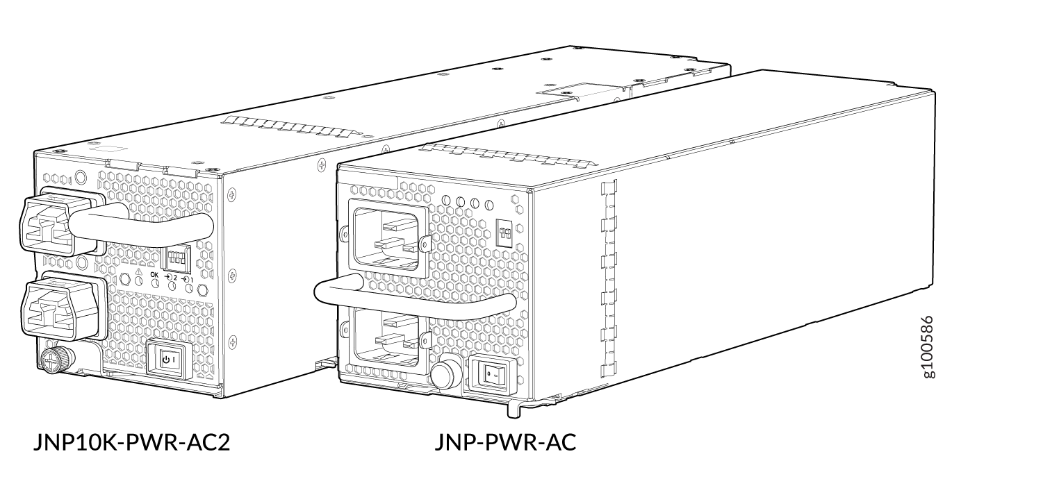
Extreme burn danger–Do not handle an HVAC or HVDC power supply running in the chassis without heat protective gloves. The JNP10K-PWR-AC2 can reach temperatures of 158°F (70°C) under running conditions.
The router is pluggable type A equipment installed in a restricted-access location. It has a separate protective earthing terminal on the chassis that must be connected to earth ground permanently to ground the chassis adequately and protect the operator from electrical hazards.
Before you begin installing the router, ensure that a licensed electrician has attached an appropriate grounding lug to the grounding cable that you supply. Using a grounding cable with an incorrectly attached lug can damage the router.
|
INP0 (Switch 1) |
INP1 (Switch 2) |
H/L (High Input 30 A/Low Input 20A) |
Output Power |
|---|---|---|---|
|
On |
On |
On (30 A) |
5500 W |
|
On |
On |
Off (20 A) |
3000 W |
|
On |
Off |
On (30 A) |
5000 W |
|
Off |
On |
On (30 A) |
5000 W |
|
On |
Off |
Off (20 A) |
2700 W |
|
Off |
On |
Off (20 A) |
2700 W |
JNP10K-PWR-AC2 Power Supply LEDs
The JNP10K-PWR-AC2 power supply has four LEDs on its faceplate: !, OK, 2, and 1. These LEDs display information about the status of the power supply. See Figure 11.
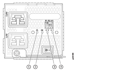
1 — ! FAULT | 3 — 2 INP2–Source input 1 |
2 — OK PWR OK | 4 — 1 INP1–Source input 0 |
Physical markings on the power supply are INP1 and INP2. These markings
correspond to INP0 and INP1 in the show chassis power output
(see Table 12).
|
Physical Marking on JNP10K-PWR-AC2 |
Show Chassis Power Command |
|---|---|
|
INP1 |
INP0 |
|
INP2 |
INP1 |
Table 13 describes the LEDs on a JNP10K-PWR-AC2 power supply.
|
LED |
Color |
State |
Description |
|---|---|---|---|
|
INP1 or INP0 in CLI output |
Amber |
Solid |
The power supply may either be switched on or switched off while the power connector for source input 0 (INP1) is unplugged. |
|
Blinking |
The input voltage is present, but is not within normal operating range. |
||
|
Green |
Solid |
The input voltage is present and within normal operating range. |
|
|
Unlit |
Off |
The power supply is switched off; voltage is zero. |
|
|
INP2 or INP1 in CLI output |
Amber |
Solid |
The power supply may either be switched on or switched off while the power connector for source input 1 (INP2) is unplugged. |
|
Blinking |
The input voltage is present, but is not within normal operating range. |
||
|
Green |
Solid |
The input voltage is present and within normal operating range. |
|
|
Unlit |
Off |
The power supply is switched off; voltage is zero. |
|
|
OK |
Green |
Solid |
The power supply output is within normal operating range. |
|
Amber |
Blinking |
The power supply output is out of the power limits or is over-current position. |
|
|
Unlit |
Off |
The power supply is switched off. |
|
|
! |
Red |
Solid |
Power supply has failed and must be replaced. |
|
Unlit |
Off |
Power supply is functioning normally. |
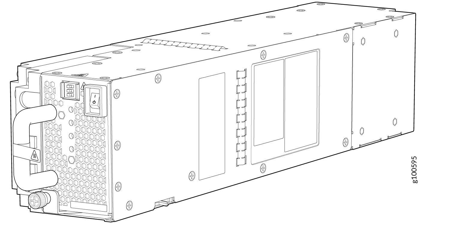
JNP10K-PWR-DC2 Power Supply
The JNP10K-PWR-DC2 power supply (see Figure 12) provides two power supplies in a single housing that accepts either 60 A or 80 A using four redundant input power feeds. PS_0 and PS_1 each have redundant input feeds: A0 and/or B0 for PS_0 and A1 and/or B1 for PS_1. The input is configured using a set of dip switches on the power supply faceplate. The output is dependant on the settings of these dip switches. See Table 14.
|
INP0 (Switch 1) |
INP1 (Switch 2) |
H/L (High Input 80 A/Low Input 60A) |
Output Power |
|---|---|---|---|
|
On |
On |
On (80 A) |
5500 W |
|
On |
On |
Off (60 A) |
4400 W |
|
On |
Off |
On (80 A) |
2750 W |
|
Off |
On |
On (80 A) |
2750 W |
|
On |
Off |
Off (60 A) |
2200 W |
|
Off |
On |
Off (60 A) |
2200 W |
The JNP10K-PWR-DC2 power supply requires a dedicated circuit breaker for each input DC feed. The DC breaker shall be rated for 80A DC with medium delay.
Do not mix power supply models in the same chassis in a running environment. JNP10K-PWR-DC and JNP10K-PWR-DC2 can coexist in the same chassis during power supply upgrades.
The router is pluggable type A equipment installed in a restricted-access location. It has a separate protective earthing terminal on the chassis that must be connected to earth ground permanently to ground the chassis adequately and protect the operator from electrical hazards.
Before you begin installing the router, ensure that a licensed electrician has attached an appropriate grounding lug to the grounding cable that you supply. Using a grounding cable with an incorrectly attached lug can damage the router.
DC power supplies are shipped only in the redundant configuration of MX10008 routers. For details about different chassis configurations, see MX10008 Components and Configurations and MX10016 Components and Configurations.
JNP10K-PWR-DC2 Power Supply LEDs
A JNP10K-PWR-DC2 power supply module has four LEDs on its faceplate: 1, 2, OK, and the symbol for fault, !. These LEDs display information about the status of the power supply. See Figure 13.
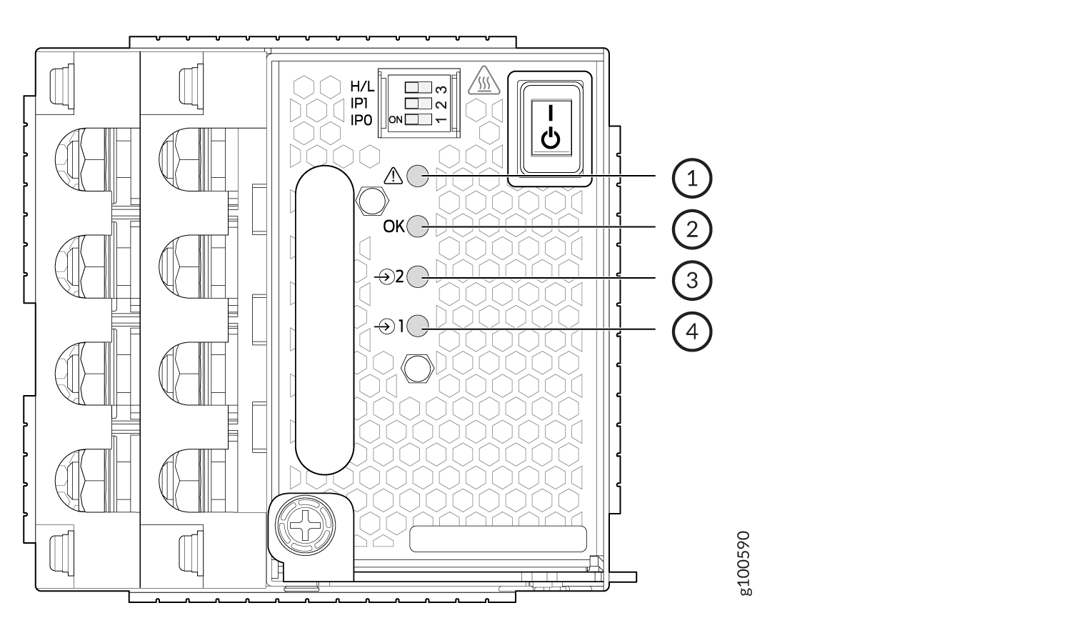
1 — !–FAULT | 3 — 2–Source input 1 |
2 — OK–Power okay | 4 — 1–Source input 0 |
You can find out the version of the firmware installed in the power supply from the
output of show system firmware command. Table 15
describes the LEDs on a JNP10K-PWR-DC2 power supply if the firmware installed in the
power supply is 768.520.772 or higher. Table 16 describes the LEDs on a JNP10K-PWR-DC2 power supply if the
firmware installed in the power supply is lower than 768.520.772.
|
Feed 0 |
Feed 1 |
State of the Power Supply Switch |
LED 1 |
LED 2 |
OK LED |
! LED |
|---|---|---|---|---|---|---|
|
Off |
Off |
Off |
Orange |
Orange |
Off |
Red |
|
A or B |
Off |
Off |
Green—Blinking |
Orange |
Off |
Red |
|
A and B |
Off |
Off |
Green |
Orange |
Off |
Red |
|
Off |
A or B |
Off |
Orange |
Green—Blinking |
Off |
Red |
|
A or B |
A or B |
Off |
Green—Blinking |
Green—Blinking |
Off |
Red—Blinking |
|
A and B |
A or B |
Off |
Green |
Green—Blinking |
Off |
Red—Blinking |
|
Off |
A and B |
Off |
Orange |
Green |
Off |
Red |
|
A or B |
A and B |
Off |
Green—Blinking |
Green |
Off |
Red—Blinking |
|
A and B |
A and B |
Off |
Green |
Green |
Off |
Off |
|
Off |
Off |
On |
Orange |
Orange |
Off |
Red |
|
A or B |
Off |
On |
Green—Blinking |
Orange |
Green |
Red |
|
A and B |
Off |
On |
Green |
Orange |
Green |
Red |
|
Off |
A or B |
On |
Orange |
Green—Blinking |
Green |
Red |
|
A or B |
A or B |
On |
Green—Blinking |
Green—Blinking |
Green |
Red—Blinking |
|
A and B |
A or B |
On |
Green |
Green—Blinking |
Green |
Red—Blinking |
|
Off |
A and B |
On |
Orange |
Green |
Green |
Red |
|
A or B |
A and B |
On |
Green—Blinking |
Green |
Green |
Red—Blinking |
|
A and B |
A and B |
On |
Green |
Green |
Green |
Off |
|
LED |
Color |
State |
Description |
|---|---|---|---|
|
1 (INP0 in CLI output) or 2 (INP1 in CLI output) |
Orange |
Solid |
Indicates that the DC power input voltage is not within normal operating range. |
|
Green |
Solid |
DC power is within operating range (-40 VDC to -72 VDC). |
|
|
Unlit |
Off |
The power supply is switched off. |
|
|
OK |
Green |
Solid |
DC power output is within normal operating range. |
|
Orange |
Blinking |
The output is out of the limits. |
|
|
! |
Red |
Solid |
Power supply has failed and must be replaced. |
|
Unlit |
Off |
Power supply is functioning normally. Or, only one input is powered and the enable router for the input that is not powered is set to ON. See Connect DC Power to an MX10008 for more information on the enable routers. |
If the 1 or 2 and the OK LED are unlit, the power cables are not installed properly or the power supply has failed.
If the 1 or LED is lit green and the OK LED is unlit, the power supply is not installed properly or the power supply has an internal failure.
If the ! LED is blinking, add a power supply to balance the power demand and supply.
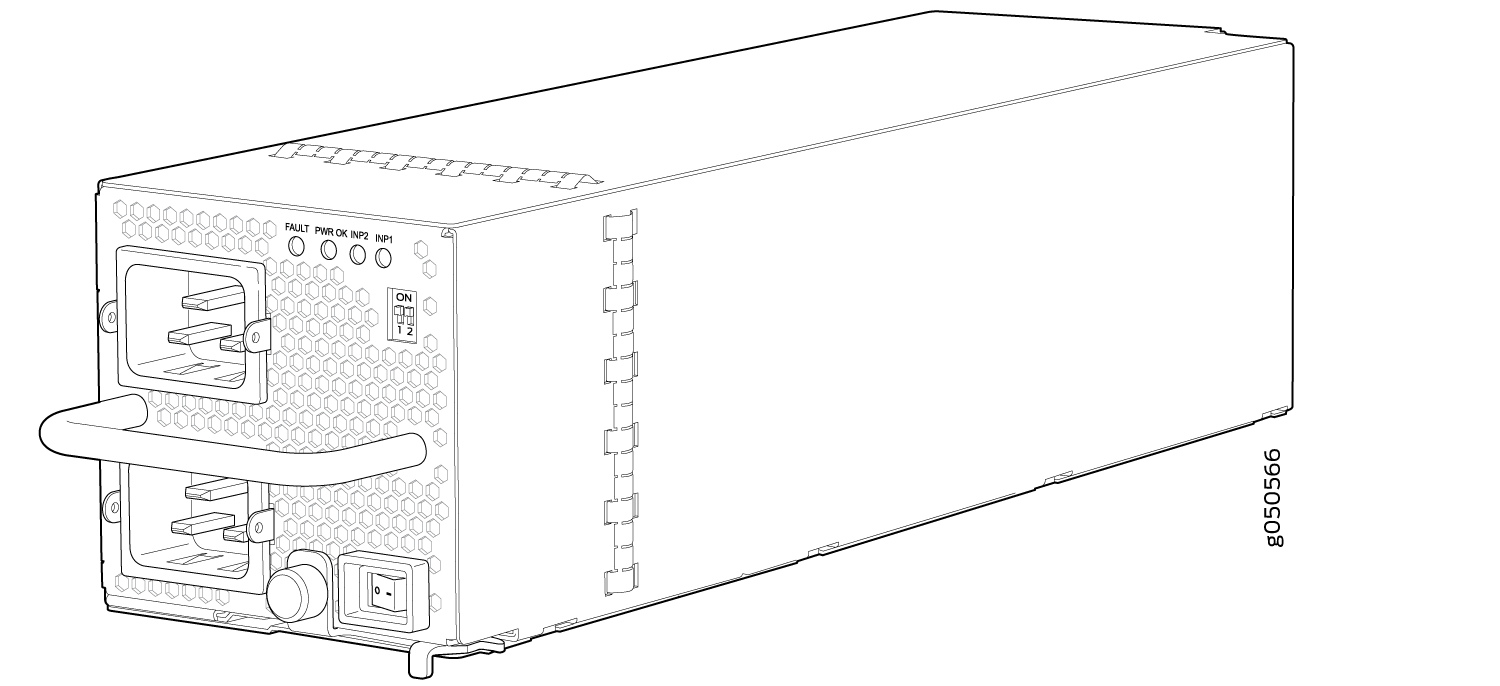
JNP10K-PWR-AC Power Supply
The AC power supply supports 200–240 VAC. The output is 12 VDC; the output power is 2700 W.
Do not mix AC and DC power supplies in the same chassis. AC and HVAC can coexist in the same chassis during the hot swap of AC for HVAC. Do not mix AC and HVAC power supplies in a running environment.
The router is pluggable type A equipment installed in a restricted-access location. It has a separate protective earthing terminal on the chassis that must be connected to earth ground permanently to ground the chassis adequately and protect the operator from electrical hazards.
Before you install the router, ensure that a licensed electrician has attached an appropriate grounding lug to the grounding cable that you supply. Using a grounding cable with an incorrectly attached lug can damage the router.
The base configuration MX10008 routers are shipped with three power supplies; base configuration MX10016 routers are shipped with five power supplies. Cover panels are installed over the remaining power supply slots. You can add additional power supplies to base configuration routers as necessary. For details about different router configurations, see MX10008 Components and Configurations.
Each JNP10K-PWR-AC power supply weighs 6.8 lb (3.08 kg) and has 2 independent 16 A rated AC inlets on the faceplate. Although each inlet provides sufficient input power to provide full output, always connect to a dedicated AC power feed to provide redundancy. Only one power feed is operational at a time.
MX10000 routers employ automatic transfer switch (ATS) technology. The system provides 2n source redundancy and n+1 power supply redundancy, allowing you to use fewer power supplies than you would require in a 2n configuration. Should one power source fail, ATS routes the power supply to the alternate source.
For redundancy, always plug the two power cords from each power supply:
INP1 into a UPS
INP2 into the public electricity supply
Each JNP10K-PWR-AC power supply has a power switch with international markings for on (|) and off (O), a fan, and four LEDs on the faceplate that indicate the status of the power supply. See Figure 14.
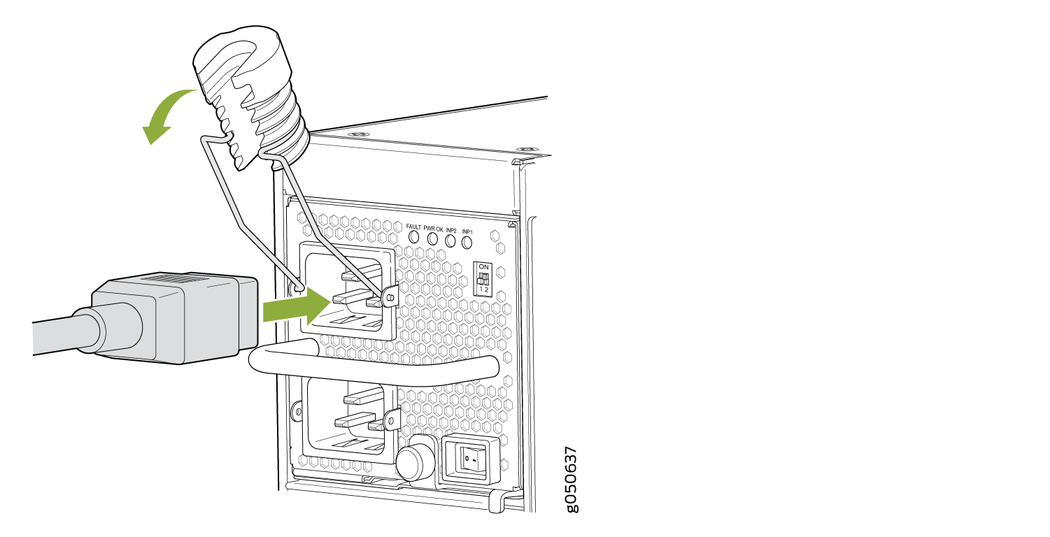
Each JNP10K-PWR-AC power supply comes with two power cord retainers that hold the power cords in place. See Figure 15. Each power cord retainer has a clip and an adjustment nut. The ends of the clip hook into the bracket holes on each side of the AC appliance inlet on the faceplate. The adjustment nut holds the power cord in the correct position. For instructions for installing the power cord retainers, see Connect AC Power to an MX10008.
Route all the AC power supply cords away from the fan trays. Make sure that the power cords do not obstruct the fan trays.
Each power supply connects to the power rail in the router. The power rail distributes the output power produced by the power supplies to different router components. Each power supply provides power to all the components in the router.
Each power supply has its own fan and is cooled by its own internal cooling system. Hot air exhausts from the rear of the chassis.
See Also
JNP10K-PWR-AC Power Supply LEDs
An AC power supply has four LEDs on its faceplate: INP1, INP2, PWR OK, and FAULT. These LEDs display information about the status of the power supply. See Figure 16.
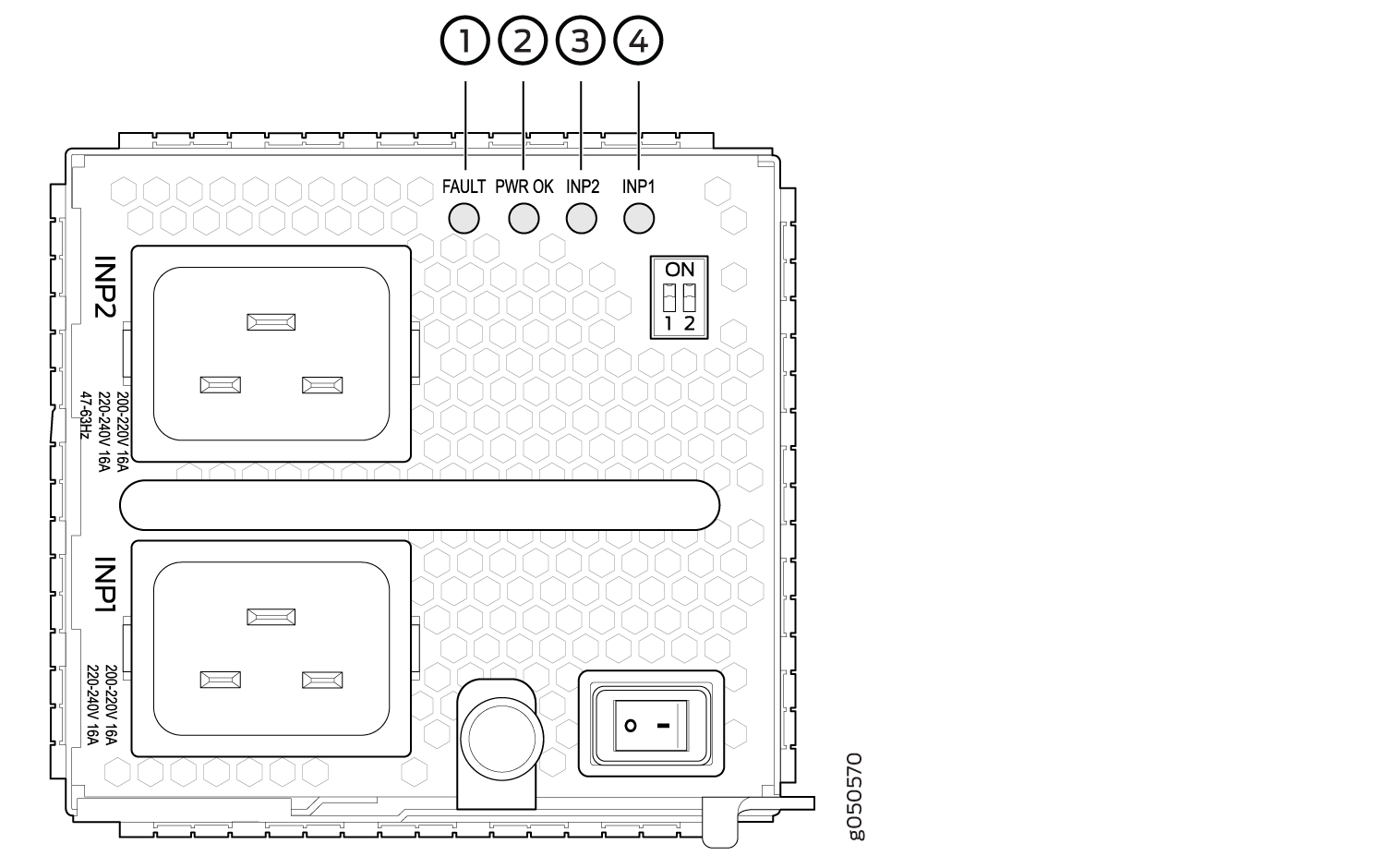
1 — FAULT | 3 — INP2–Source input 1 |
2 — PWR OK | 4 — INP1–Source input 0 |
Table 17 describes the LEDs on a JNP10K-PWR-AC power supply.
LED |
Color |
State |
Description |
|---|---|---|---|
INP1 (INP0 in CLI output) or INP2 (INP1 in CLI output) |
Amber |
Blinking |
Indicates that the AC power input voltage is not within normal operating range. |
Green |
Solid |
AC is within operating range (200–240 VAC). |
|
Dark |
Unlit |
The power supply is switched off. |
|
PWR OK |
Green |
Solid |
DC power output is within normal operating range. |
Amber |
Blinking |
AC power output is out of the normal operating range. |
|
FAULT |
Dark |
Unlit |
Power supply is functioning normally. |
Red |
Solid |
Power supply has failed and must be replaced. Or, only one input is powered and the enabled router for the input that is not powered is set to ON. See Install a JNP10K-PWR-AC Power Supply for more information about the enable routers. |
If the INP1 or INP2 LED and the PWR OK LED are unlit, the AC power cord is not installed properly or the power supply has failed.
If the INP1 or INP2 LED is lit and the PWR OK LED is unlit, the AC power supply is not installed properly or the power supply has an internal failure.
See Also
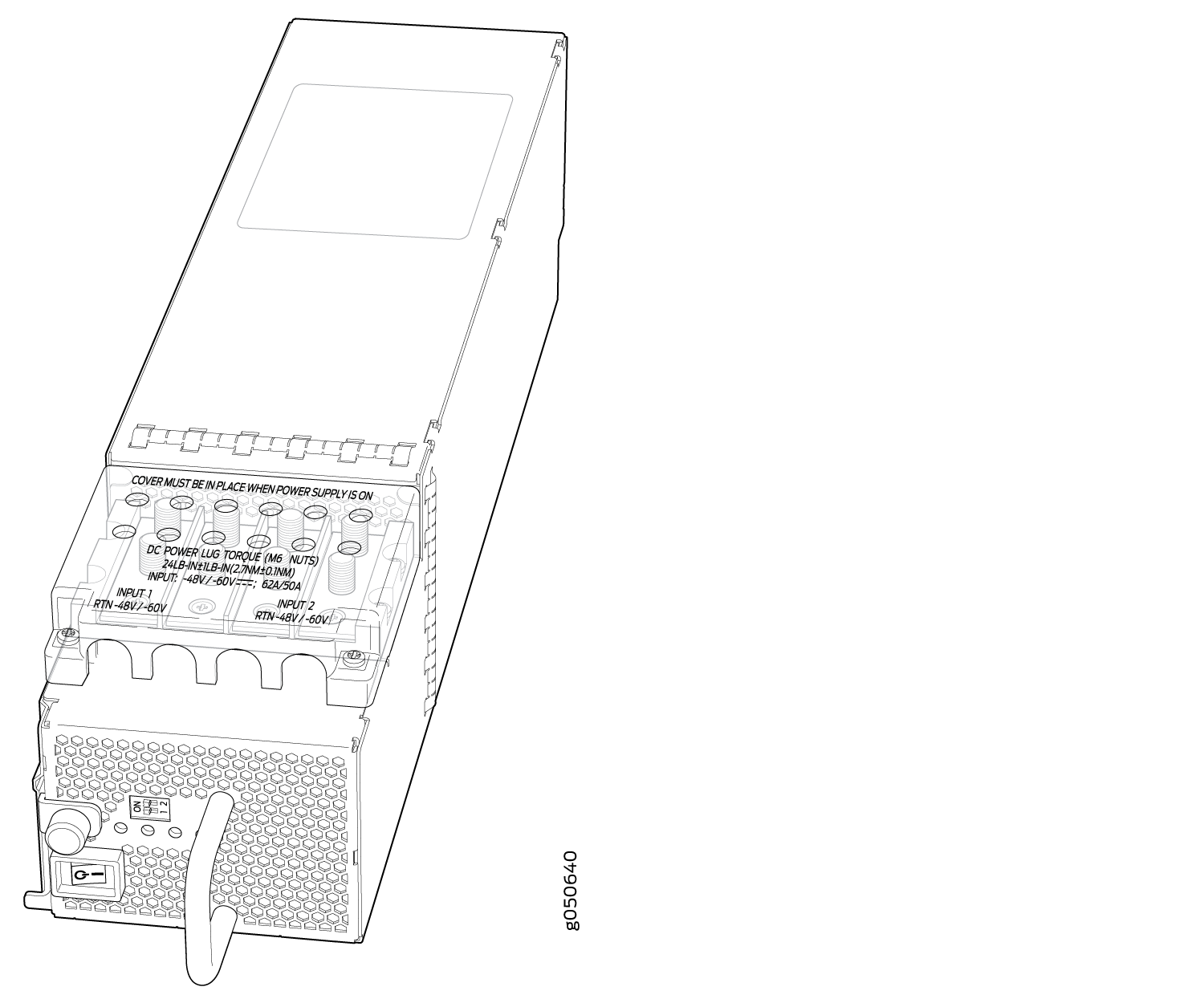
JNP10K-PWR-DC Power Supply
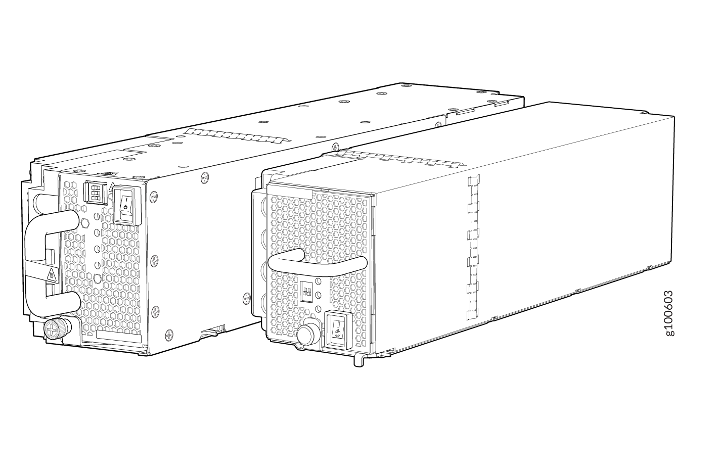
MX10008 routers support three types of DC power supply modules:
JNP10K-PWR-DC—A 2500-W, 12-VDC dual power supply.
JNP10K-PWR-DC2—A 5500-W, 12-VDC quad input power supply. For details on this power supply, see JNP10K-PWR-DC2 Power Supply.
JNP10K-PWR-AC2—An AC, high-voltage alternating current (HVAC,) or high-voltage direct current (HVDC) power supply. In high power mode, this power supply provides 12.3 V, 5000 W with a single feed and 5500 W with dual feeds. For details on this power supply, see JNP10K-PWR-AC2 Power Supply.
All three power supplies fit into a power slot bay, but the JNP10K-PWR-AC2 and JNP10K-PWR-DC2 are longer and protrude from the bay when fully inserted into the chassis. See Figure 17.
Do not mix power supply models in the same chassis in a running environment. DC and HVDC can coexist in the same chassis during the hot swap of DC for HVDC.
The DC power supply, JNP10K-PWR-DC, is a 2500-W, 12-VDC, dual input power supply. The output of each DC power supply is 12-VDC. The output power is 2500 W.
The router is pluggable type A equipment installed in a restricted-access location. It has a separate protective earthing terminal on the chassis that must be connected to earth ground permanently to ground the chassis adequately and protect the operator from electrical hazards.
Before you install the router, ensure that a licensed electrician has attached an appropriate grounding lug to the grounding cable that you supply. Using a grounding cable with an incorrectly attached lug can damage the router.
DC power supplies are shipped only in the redundant configuration of MX10000 routers. For details about different chassis configurations, see MX10008 Components and Configurations and MX10016 Components and Configurations.
JNP10K-PWR-DC power supplies can use the standard power bus or the enhanced power bus. All MX10016 chassis ship with the enhanced power bus; to determine whether an MX10008 has the standard or enhanced power bus, see MX10008 Status Panel LEDs.
Each JNP10K-PWR-DC power supply weighs approximately 6 lb (2.7 kg) and has two independent pairs of DC input lugs (Input 1, RTN, –48V/–60V and Input 2, RTN, –48V/–60V) on the faceplate of the power supply. Each inlet requires a dedicated DC power feed. Although each inlet provides sufficient input power to provide full output, always connect to a dedicated DC power feed to provide redundancy. Only one power feed is operational at a time.
DC power models employ electronic A-B input selection. It provides 2n source redundancy and n+1 power supply redundancy using fewer power supplies than you would require in a 2n configuration. Should one power source fail, electronic A-B input selection routes the power supply to the alternate source.
Each JNP10K-PWR-DC power supply has a power switch with international markings for on (|) and off (O), a fan, and four LEDs on the faceplate that indicate the status of the power supply. See Figure 18.
The JNP10K-PWR-DC power supply requires a dedicated circuit breaker for each input DC feed. The chosen breaker should be sized to deliver 60 A of input current.
Each power supply connects to the combined power rail in an MX10000 router. The power rail distributes the output power produced by the power supplies to different router components. Each DC power supply provides power to all the components in the router.
Route all the DC power supply cords away from the fan trays. Make sure that the power cords do not obstruct the fan trays.
A JNP10K-PWR-DC power supply can operate with only one input DC feed connected. The Routing Control Board only enables the components for which sufficient power is available.
Each JNP10K-PWR-DC power supply has its own fan and is cooled by its own internal cooling system. The airflow is from the front of the power supply to the back. Hot air exhausts from the rear of the chassis.
See Also
JNP10K-PWR-DC Power Supply LEDs
The JNP10K-PWR-DC power supply has four LEDs on its faceplate: INP1, INP2, PWR OK, and FAULT. These LEDs display information about the status of the power supply. See Figure 19.
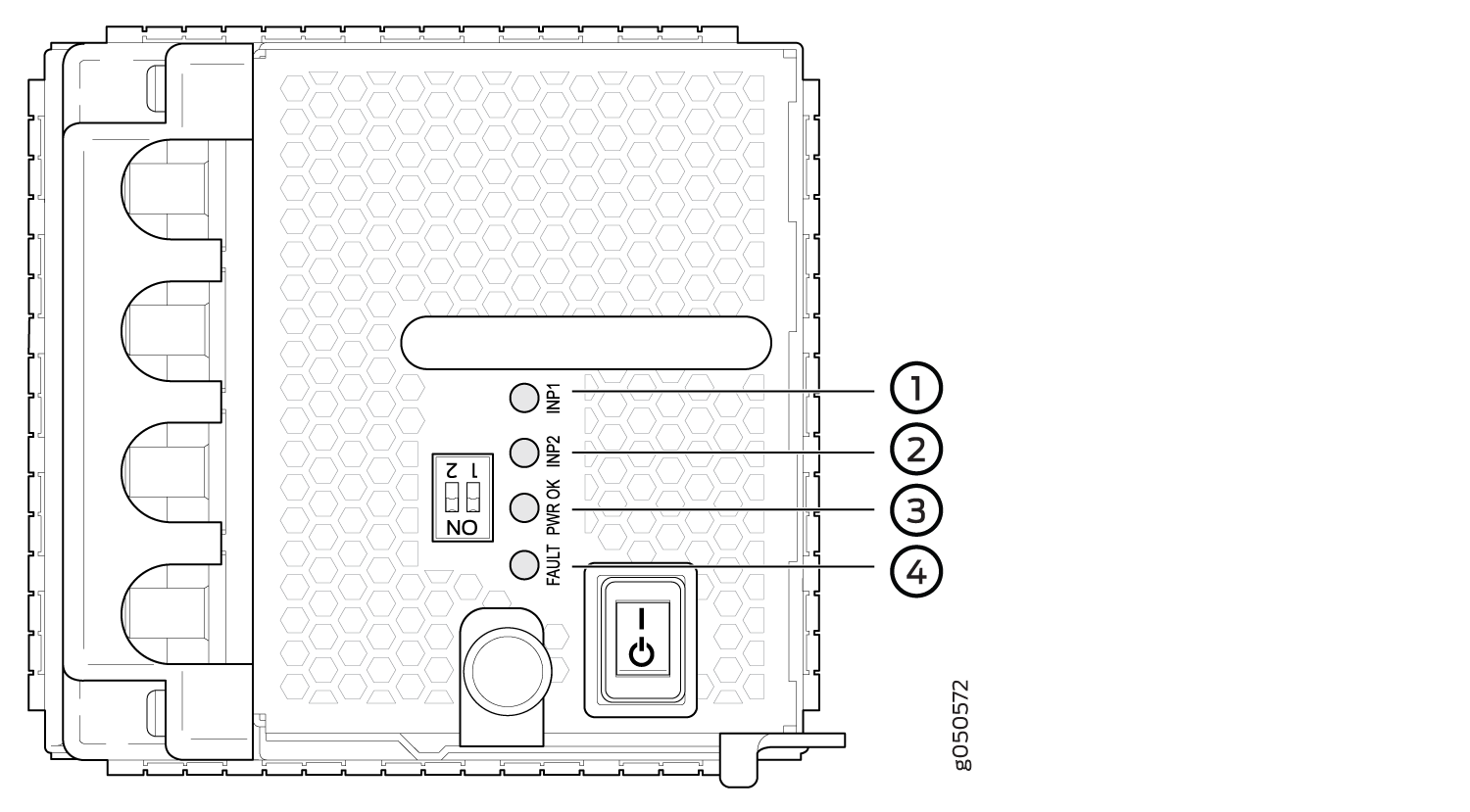
1 — INP1–Source input 0 | 3 — PWR OK |
2 — INP2–Source input 1 | 4 — FAULT |
Table 18 describes the LEDs in an MX10008.
LED |
Color |
State |
Description |
|---|---|---|---|
INP1 or INP2 |
Amber |
Blinking |
Indicates that the DC power input voltage is not within normal operating range. |
Green |
Solid |
DC power is within operating range (-40 VDC to -72 VDC). |
|
Unlit |
Off |
The power supply is switched off. |
|
PWR OK |
Green |
Solid |
DC power output is within normal operating range. |
Amber |
Blinking |
DC power output is out of the normal operating range. |
|
FAULT |
Red |
Solid |
Power supply has failed and must be replaced. |
Unlit |
Off |
The power supply is functioning normally. Or, only one input is powered and the enable router for the input that is not powered is set to ON. See Connect DC Power to an MX10008 for more information on the enable switches. |
If the INP1 or INP2 and the PWR OK LED are unlit, the power cords are not installed properly or the power supply has failed.
If the INP1 or INP2 LED is lit green and the PWR OK LED is unlit, the power supply is not installed properly or the power supply has an internal failure.
If the FAULT LED is blinking, add a power supply to balance the power demand and supply.