MX10008 Chassis
MX10008 Chassis Physical Specifications
The MX10008 modular chassis is a rigid sheet-metal structure that houses the other router components. You can mount up to three MX10008 routers in a standard 19-in. 4-post rack (42 U) rack provided the rack can handle the combined weight and there is adequate power and cooling. Table 1 summarizes the physical specifications of the chassis. See Figure 1.
| Description | Weight | Height | Width | Depth |
|---|---|---|---|---|
|
Chassis, spare |
145.2 lb (65.86 kg) |
22.6 in. (57.4 cm) |
17.4 in. (44.2 cm) Note:
The outer edges of the chassis flange extend the width to 19 in. (48.3 cm). |
32 in. (81.28 cm) chassis only |
|
Base AC configuration MX10008-BASE |
294 lb (133 kg) | 22.6 in. (57.4 cm) |
17.4 in. (44.2 cm) Note:
The outer edges of the chassis flange extend the width to 19 in. (48.3 cm). |
35 in. (88.9 cm) with JNP10K-PWR-AC power supplies 42.4 in. (107.7 cm) with EMI door |
|
Base AC configuration with JNP10K-PWR-AC2 components MX10008-BASE-AC2 |
330 lb (150 kg) |
22.6 in. (57.4 cm) |
17.4 in. (44.2 cm) Note:
The outer edges of the chassis flange extend the width to 19 in. (48.3 cm). |
36.7 in. (93.2 cm) with JNP10K-PWR-AC2 power supplies 44.1 in. (112 cm) with EMI door |
| Base DC
configuration MX10008-BASE -DC |
291 lb (132 kg) |
22.6 in. (57.4 cm) |
17.4 in. (44.2 cm) Note:
The outer edges of the chassis flange extend the width to 19 in. (48.3 cm). |
35 in. (88.9 cm) with JNP10K-PWR-DC power supplies 42.4 in. (107.7 cm) with EMI door |
| Base DC configuration with JNP10K-PWR-DC2
components MX10008-BASE-DC2 |
320 lb (145 kg) |
22.6 in. (57.4 cm) |
17.4 in. (44.2 cm) Note:
The outer edges of the chassis flange extend the width to 19 in. (48.3 cm). |
36.7 in. (93.2 cm) with JNP10K-PWR-DC2 power supplies 44.1 in. (112 cm) with EMI door |
| Redundant AC
configuration MX10008-PREMIUM-REDUNDANT-AC |
336 lb (152 kg) |
22.6 in. (57.4 cm) |
17.4 in. (44.2 cm) Note:
The outer edges of the chassis flange extend the width to 19 in. (48.3 cm). |
35 in. (88.9 cm) with JNP10K-PWR-AC power supplies 42.4 in. (107.7 cm) with EMI door |
| Redundant AC configuration with JNP10K-PWR-AC2
components MX10008-PREMIUM-REDUNDANT-AC2 |
388 lb (176 kg) |
22.6 in. (57.4 cm) |
17.4 in. (44.2 cm) Note:
The outer edges of the chassis flange extend the width to 19 in. (48.3 cm). |
36.7 in. (93.2 cm) with JNP10K-PWR-AC2 power supplies 44.1 in. (112 cm) with EMI door |
| Redundant DC
configuration MX10008-PREMIUM-REDUNDANT-DC |
331 lb (150 kg) |
22.6 in. (57.4 cm) |
17.4 in. (44.2 cm) Note:
The outer edges of the chassis flange extend the width to 19 in. (48.3 cm). |
35 in. (88.9 cm) with JNP10K-PWR-DC power supplies 42.4 in. (107.7 cm) with EMI door |
| Redundant DC configuration with JNP10K-PWR-DC2 components
MX10008-PREMIUM-REDUNDANT-DC2 |
369 lb (168 kg) |
22.6 in. (57.4 cm) |
17.4 in. (44.2 cm) Note:
The outer edges of the chassis flange extend the width to 19 in. (48.3 cm). |
36.7 in. (93.2 cm) with JNP10K-PWR-DC2 power supplies 44.1 in. (112 cm) with EMI door |
| MX10K-LC2101 Line Card |
31.57 lb (14.32 kg) |
1.89 in. (48.01 mm) |
17.2 in (436.88 mm) |
19.05 in. (484 mm) (Excluding FRU Ejector) |
| MX10K-LC480 Line Card |
21.6 lb (9.8 kg) |
1.89 in. (48.01 mm) |
17.2 in (436.88 mm) |
19.05 in. (484 mm) (Excluding FRU Ejector) |
|
MX10K-LC9600 Line Card |
27 lb (12.24 kg) |
1.89 in. (48.01 mm) |
17.2 in (436.88 mm) |
19.05 in. (484 mm) (Excluding FRU Ejector) |
|
MX10K-LC4800 Line Card |
40 lb (18.14 kg) |
1.89 in. (4.8 cm) |
17.2 in. (43.68 cm) |
19.05 in. (48.3 cm) (excluding FRU ejector) |
|
MX10K-LC4802 Line Card |
40 lb (18.14 kg) |
1.89 in. (4.8 cm) |
17.2 in. (43.68 cm) |
19.05 in. (48.3 cm) (excluding FRU ejector) |
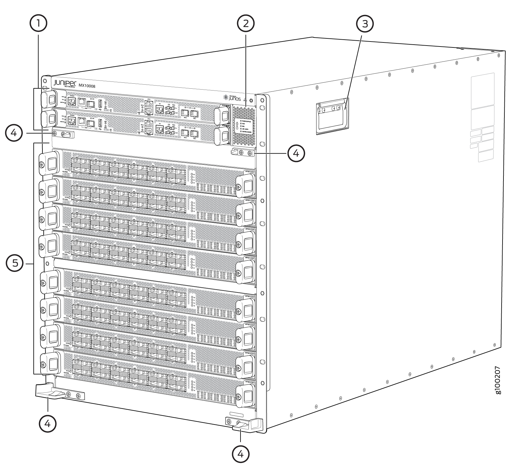
1 — Routing and Control boards | 4 — Mounting holes for front panel |
2 — Status panel | 5 — Line cards |
3 — Handles |
The handles on each side of the chassis facilitate the fine-tune positioning of the chassis on the mounting brackets. Do not use the handles to lift the chassis, even when the chassis is empty. See Mounting an MX10008 in a 4-Post Rack Using a Mechanical Lift or Manually Mounting an MX10008 in a 4-Post Rack for instructions for properly moving a loaded chassis.
See Also
Field-Replaceable Units in an MX10008
Field-replaceable units (FRUs) are router components that you can replace at your site. Routers use these types of FRUs:
Hot-insertable and hot-removable—You can remove and replace these components without powering off the router or disrupting the routing function.
Hot-pluggable—You can remove and replace these components without powering off the router, but the routing function is interrupted until you replace the component.
Table 2 lists the FRUs and their types for the MX10008 routers.
FRU |
Type |
|---|---|
Power supplies |
Hot-insertable and hot-removable. |
Fan trays |
Hot-insertable and hot-removable. |
Fan tray controllers |
Hot-insertable and hot-removable. |
Routing and Control Board (RCB) |
Redundant configuration:
Base configuration:
|
Switch Fabric Boards (SFBs) |
Hot-insertable and hot-removable. We recommend that you take the SFBs offline before removing
them to avoid traffic loss while the router fabric is being reconfigured.
You can take SFBs offline by using the |
Line cards |
Hot-insertable and hot-removable. We recommend that you take line cards offline before removing
them. You can take line cards offline by using the Note:
Line cards are not part of the base configuration or redundant configuration. You must order them separately. |
Optical transceivers |
Hot-insertable and hot-removable. See MX10008 Optical Transceiver and Cable Support for the Junos OS release in which the transceivers were introduced. |
If you have a Juniper Care service contract, register any addition, change, or upgrade of hardware components at https://www.juniper.net/customers/support/tools/updateinstallbase/. Failure to do so can result in significant delays if you need replacement parts. This note does not apply if you replace an existing component with the same type of component.
See Also
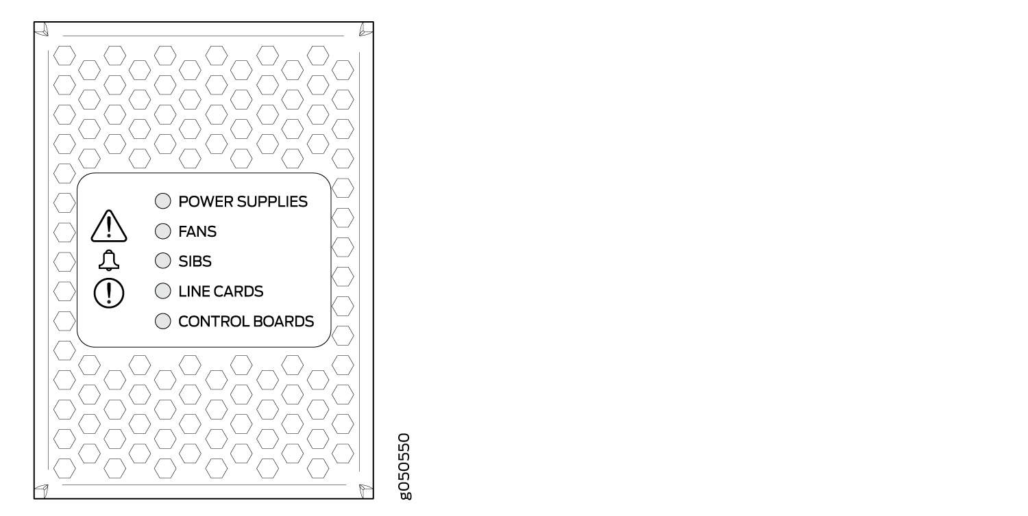
MX10008 Status Panel LEDs
The status panel of the MX10008 routers has two purposes:
-
Shows the overall status of the chassis
-
Indicates the type of power bus internal to the chassis
Some chassis ship with an enhanced power bus to support the power needs of higher wattage line cards.
The status panel indicates chassis status through a set of five bi-color LEDs. See Figure 2 for a chassis status panel with the standard power bus.
Chassis with enhanced power bus has the same set of five bi-color LEDs, but also have an azure blue line to indicate the enhanced power bus (see Figure 3).
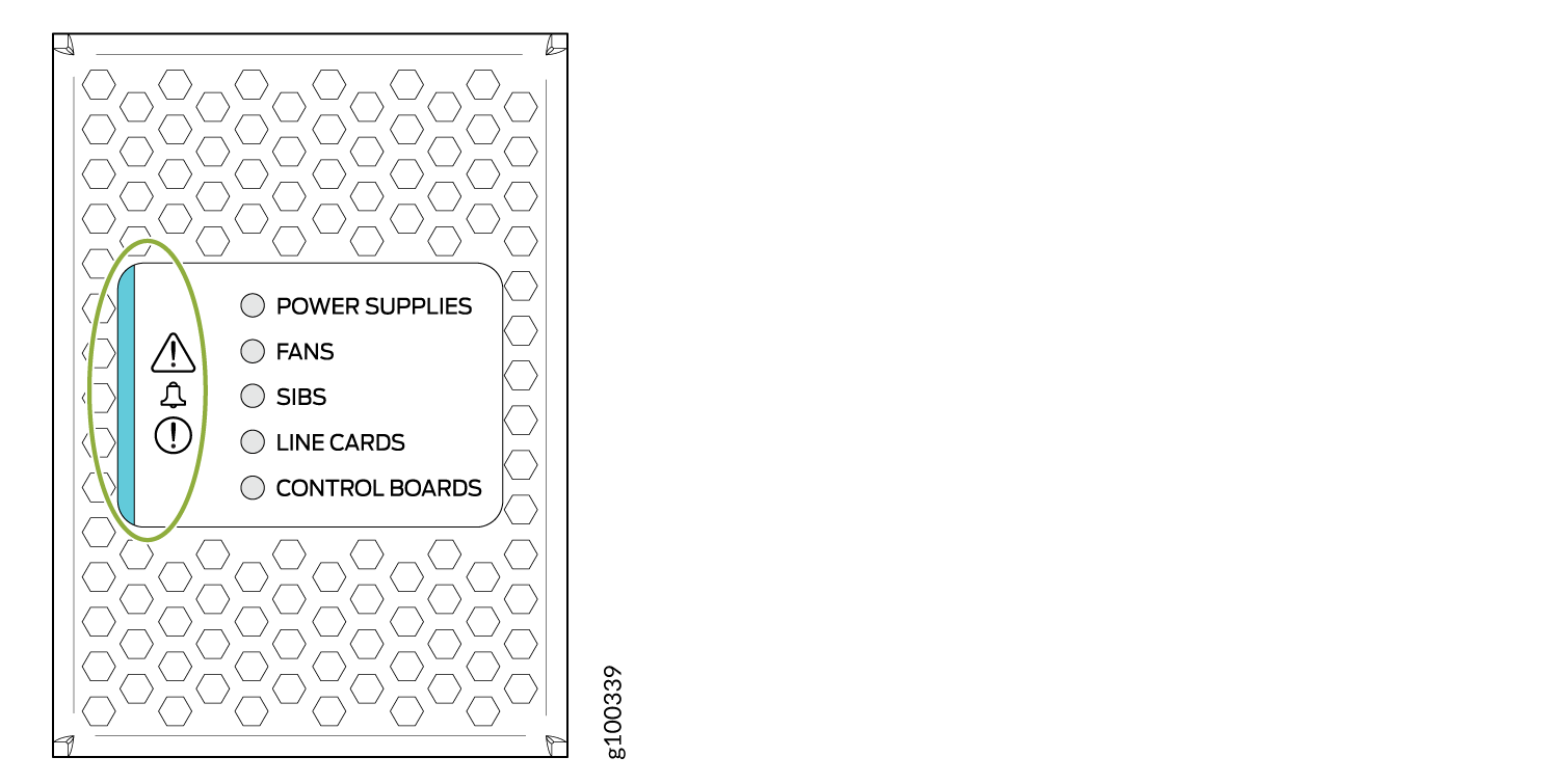
Table 3 describes the status panel LEDs.
|
Name |
Color |
State |
Description |
|---|---|---|---|
|
Power supplies |
Green |
On steadily |
All of the power supplies are online and operating normally. |
|
Amber |
Blinking |
One or more of the power supplies has an error. |
|
|
None |
Off |
None of the power supplies is receiving power. |
|
|
Fans |
Green |
On steadily |
The fans and the fan tray controllers are online and operating normally. |
|
Amber |
Blinking |
There is an error in a fan or in one of the fan tray controllers. |
|
|
None |
Off |
The fan tray controllers and fan trays are not receiving power. |
|
|
SFBs |
Green |
On steadily |
All installed Switch Fabric Boards (SFBs) are online. |
|
Amber |
Blinking |
There is a hardware error in one or more SFBs. |
|
|
None |
Off |
All the SFBs are offline. |
|
|
Line cards |
Green |
On steadily |
All installed line cards are online. |
|
Amber |
Blinking |
There is a hardware error in one or more line cards. |
|
|
None |
Off |
All the line cards are offline. |
|
|
Routing and Control Boards |
Green |
On steadily |
All installed RCBs are online. |
|
Amber |
Blinking |
One or more Routing and Control Boards have an error condition. |
|
|
None |
Off |
The installed Routing and Control Boards are offline. |
|
|
Alarms |
Amber 
|
On steadily |
Minor (amber)—Indicates a noncritical condition on the device that, if left unchecked, might cause an interruption in service or degradation in performance. An amber alarm condition requires monitoring or maintenance. For example, a missing rescue configuration generates an amber system alarm. |
|
Red 
|
On steadily |
Major (red)—Indicates a critical situation on the device that has resulted from one of the following conditions:
A red alarm condition requires immediate action. |
See Also
MX10008 Optional Equipment
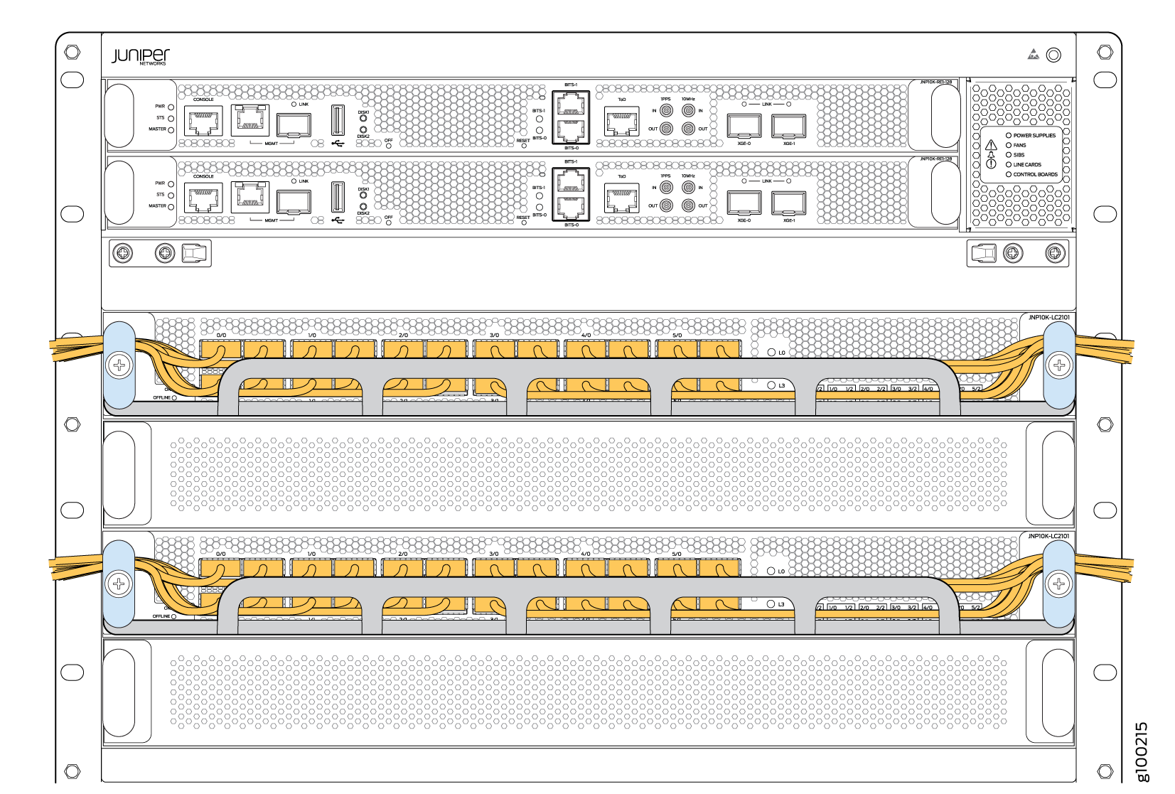
The MX10008 router supports the cable management system as an optional equipment.
The cable management system (see Figure 4) enables you to route optical cables away from the line card ports for better airflow through the chassis. Using this optional system also makes it easier to use cable ties or strips to organize the cabling.
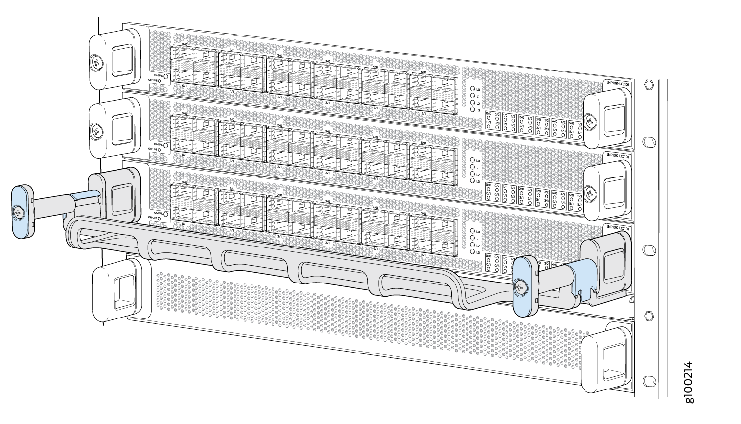
The cable management system comprises a set of handle extensions and a tray that snaps to the extensions (see Figure 5) for an individual line card. The handle extensions can be used with or without the cable tray. It is not necessary to remove the handle extensions if you want to remove a line card.
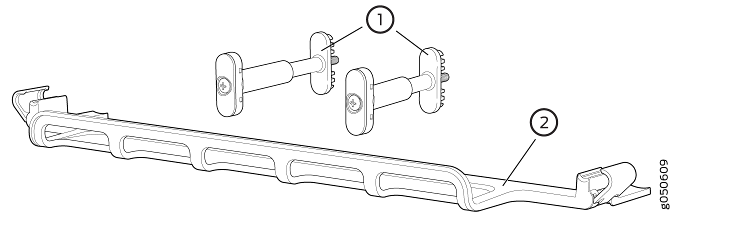
1 — Handle extensions | 2 — Cable tray |
Cables are draped across or under the handle extensions and then secured with cable wraps (see Figure 6).