Removing and Installing MX10008 MPC Components
An MX10008 Modular Port Concentrator (MPC) is a field-replaceable unit (FRU) that you can install in any of the line card slots on the front of the chassis. An MPC is hot-insertable and hot-removable; you can remove and replace them without powering off the router or disrupting router functions.
When upgrading the firmware for any line card, be sure the power supply is stable. Prevent any power outages, and do not remove the line card from the router. Losing power to the line card during a firmware upgrade can cause serious damage.
How to Handle and Store an MX10008 MPC
Handling MPCs
Pay proper attention to how you are handling MPCs. Because MPCs are installed horizontally, we recommend that you hold them by the sides of the units when they are not in the chassis. A running MPC can be hot, use heat protective gloves, and allow the unit to cool half way out of the chassis before removing.
To handle e an MPC properly:
-
Take care not to strike the unit against any object as
you carry it.
CAUTION:
Never hold an MPC by the connector edge. The connectors are fragile. You cannot seat an MPC properly if the connectors are damaged (see Figure 1).
Figure 1: Connector Edge of an MPC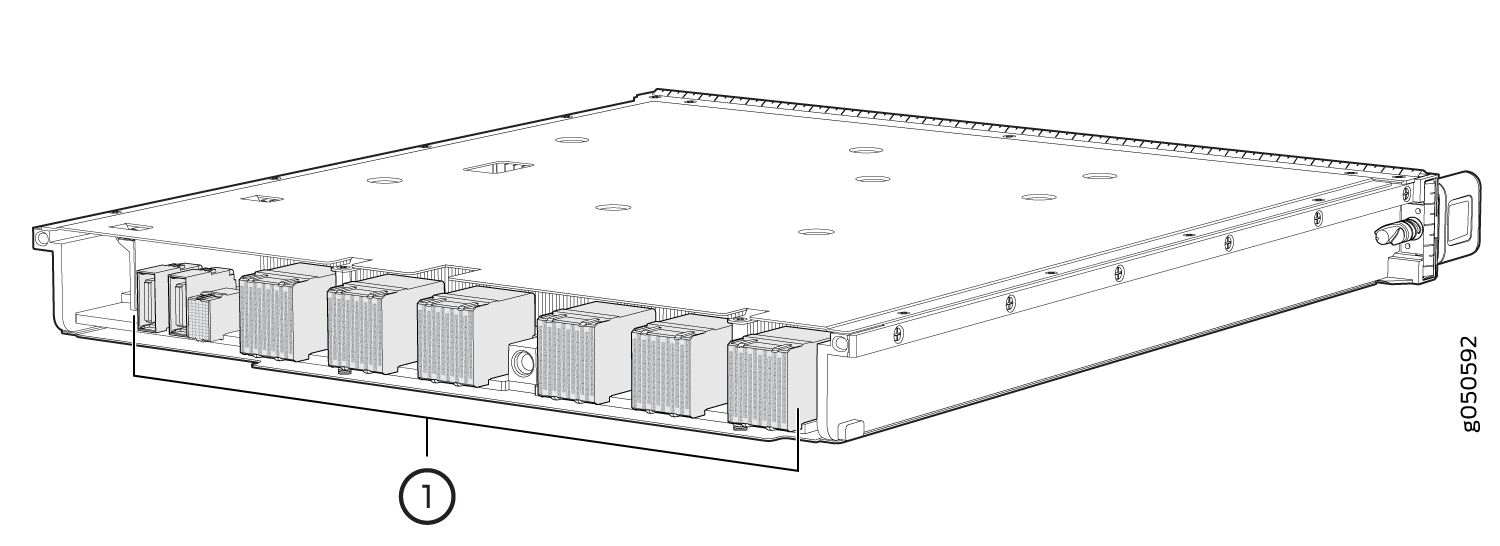 1—
1—Connectors
Storing MPCs
You must store MPCs either in the chassis or in a spare shipping container, horizontally and sheet-metal side down. Do not stack these units on top of one another or on top of any other component. Place each unit in an individual antistatic bag or separately on an antistatic mat placed on a flat, stable surface.
Because these MPCs are heavy, and because electrotatic bags are fragile, inserting an MPC into the bag is best done by two people.
The MX10K-LC9600 line cards are shipped with a protective plastic cover on the fabric interface connectors. The plastic cover keeps the connectors clean and free of dust and other particles. When you remove MX10K-LC9600 line card from the router, re-insert the protective plastic cover on the fabric interface connectors and then place the line card in an antistatic bag or on an antistatic mat placed on a flat, stable surface.
To insert an MPC into an antistatic bag with the help of another person:
- Hold the unit horizontally with the faceplate toward you.
- Have the second person slide the opening of the antistatic bag over the connector edge and then pull the bag to cover the unit.
To insert an into a bag by yourself:
-
Lay the unit horizontally on an antistatic mat that is on a flat, stable surface, with the sheet-metal side of the unit facing down.
-
Orient the unit with the faceplate toward you.
-
Carefully insert the connector edge into the opening of the bag, and then pull the bag toward you to cover the unit.
Install an MPC in an MX10008
Before you install a line card in the router chassis:
-
Ensure that you have taken the necessary precautions to prevent antistatic discharge (ESD) damage. See Prevention of Electrostatic Discharge Damage.
-
Inspect the connector edge of the MPC for physical damage. Installing a damaged MPC might damage the router.
-
Ensure that you know how to handle and store the line card (see
-
Ensure that the router has sufficient power to power the line card while maintaining its n+1 power redundancy. To determine whether the router has enough power available for the line card, use the
show chassis
                           power-budget-statistics
command. -
In addition to the MPC, ensure that you have the following parts and tools available to install an MPC in the router:
-
ESD grounding strap
-
An antistatic bag or an antistatic mat
-
To install an MPC in the router chassis:
-
Wrap and fasten one end of the ESD grounding strap around your bare wrist
and connect the other end of the strap to one of the ESD points on the
chassis. An ESD point is located above the status LED panel on the front of
the router chassis. See Figure 2.
Figure 2: ESD Point for MX10008 Chassis Front
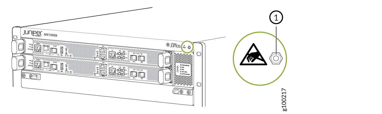 1—
1—ESD point
-
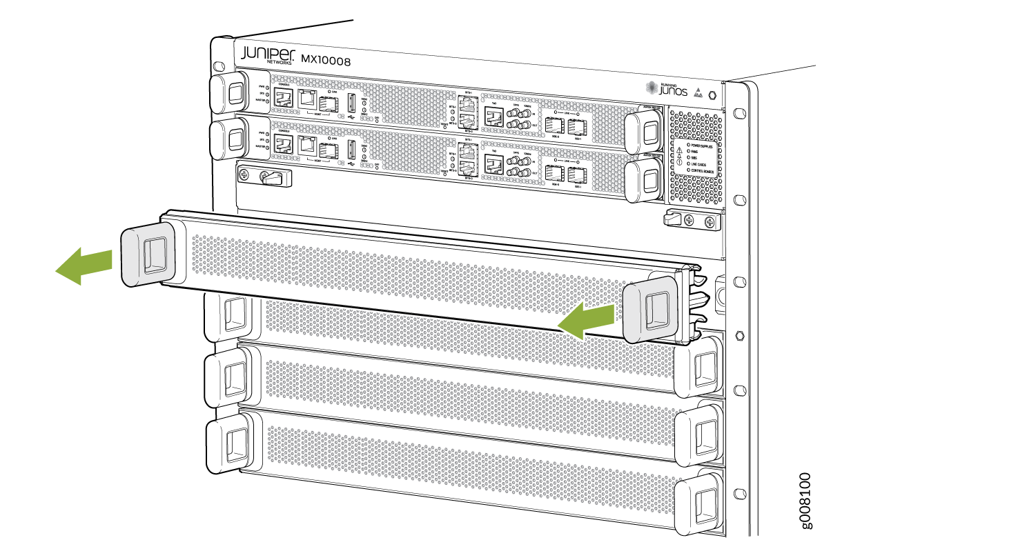
Remove the MPC cover by grasping the handles and pulling straight out to
expose the slot for the MPC. See Figure 3.
Figure 3: Remove the MPC Cover
-
Remove the MPC from the antistatic bag and place on the antistatic mat.
Inspect it for any damage before installing it into the chassis.
CAUTION:
Do not lift the MPC by holding the edge connectors or the handles on the faceplate. Neither the handles nor the edge connectors can support the weight of the line card. Lifting the line card by the handles or edge connectors might bend them, which would prevent the line cards from being properly seated in the chassis. See Figure 4.
Figure 4: MPC Connectors
1—Connectors
-
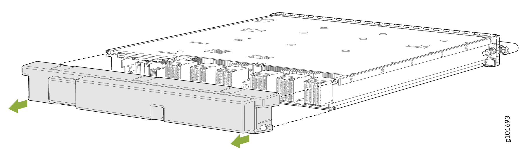
If you are installing MX10K-LC9600, remove the protective plastic cover on
the fabric interface connectors and save the plastic cover for future use
(see Figure 5).
Figure 5: Removing Protective Plastic Cover from the MX10K-LC9600 Interface Connectors
-
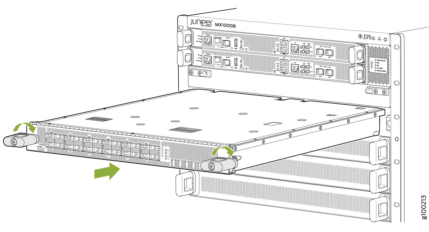
Align the sides of the MPC with the guides inside the chassis slot. Slide
the MPC all the way into the slot until the handle holes align and you feel
resistance. See Figure 6.
Figure 6: Installing an MPC
Verify that the MPC is functioning correctly by using the show chassis fpc and show chassis fpc
pic-status commands.
You can install the optional cable management kit after the card is installed.
Remove an MPC
If you have the optional cable management system, it is not necessary to remove the cable management system before removing the MPC. However, we recommend that you take the MPCs offline before removing them.
Before you remove an MPC from the router chassis:
-
Ensure that you have taken the necessary precautions to prevent electrostatic discharge (ESD) damage (see Prevention of Electrostatic Discharge Damage).
-
Ensure that you know how to handle and store the MPC (see How to Handle and Store an MX10008 MPC).
-
Ensure you have the following parts and tools available to remove an MPC from an MX10008 chassis:
-
ESD grounding strap
-
An antistatic bag or an antistatic mat
Note:Placing an MPC in an antistatic bag might require a second person to assist with sliding the MPC into the bag.
-
Replacement MPC or line card blank (JNP10K-LC-BLNK) for the empty slot
-
Heat resistant gloves
-
Do not remove the MPC unless you have a replacement MPC or a line card blank (JNP10K-LC-BLNK) available.
If you are not installing another MPC into the empty card slot within a short time, install the line card blank into the slot to maintain proper airflow in the card cage.
The air filters in the line card blanks will prevent dust and other particles entering the chassis. If an empty MPC slot is not covered, dust and other particles may accumulate on the connector pins of the installed MPCs and SFBs and affect the performance of the router.
When you remove an MPC, the router continues to function, although the interfaces that are installed on the MPC that is being removed no longer function.
To remove an MPC from an MX10008 router chassis:
-
Wrap and fasten one end of the ESD grounding strap around your bare wrist
and connect the other end of the strap to one of the ESD points on the
chassis. An ESD point is located above the status LED panel on the front of
the router chassis. See Figure 7.
Figure 7: ESD Point for MX10008 Chassis Front
1—
ESD point
-
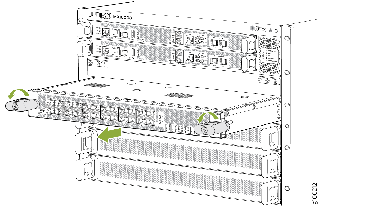
Simultaneously turn both the ejector handles of the MPC counterclockwise to
unseat the MPC.
Figure 8: Removing an MPC
-
Grasp the handles, and holding the MPC straight, slide it halfway out of
the card cage.
CAUTION:
The MPC and the handles may be hot. Allow a few minutes for the MPC and handles to cool by pulling out the MPC halfway out of the chassis.
-
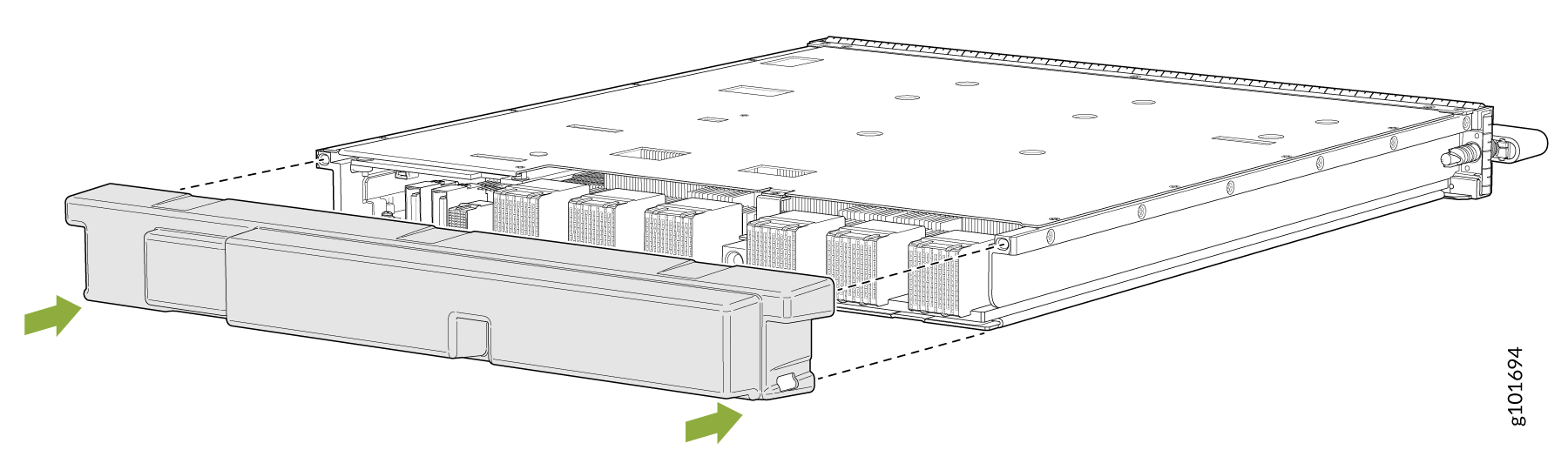
If you removed an MX10K-LC9600 from the router, re-insert the protective
plastic cover on the fabric interface connectors of the line card to keep
the connectors clean and free of dust and other particles (see Figure 9).
Figure 9: Inserting Protective Plastic Cover on MX10K-LC9600 Interface Connectors
Install the Cable Management System
The cable management system is an optional kit that can be ordered to organize and protect optical cabling attached to the line cards. After a card is installed, you can still remove the line card without needing to remove the cable management system.
Ensure that you have the following parts and tools available to install the cable management system on a line card:
-
Phillips (+) screwdriver, number 2
-
The cable management system
To install the cable management system (see Figure 10):
-
Open the shipping carton of the cable management system
and check that you have:
-
Two handle extensions
-
One cable tray
Figure 10: Cable Management System Components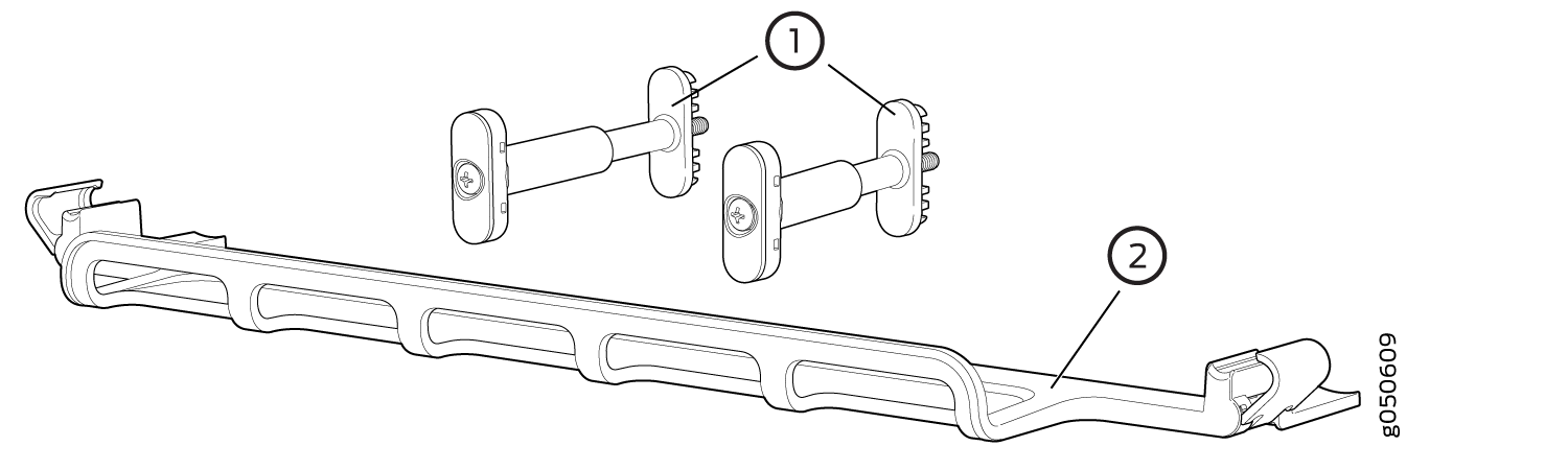 1—
1—Handle extensions
2—Cable tray
-
-
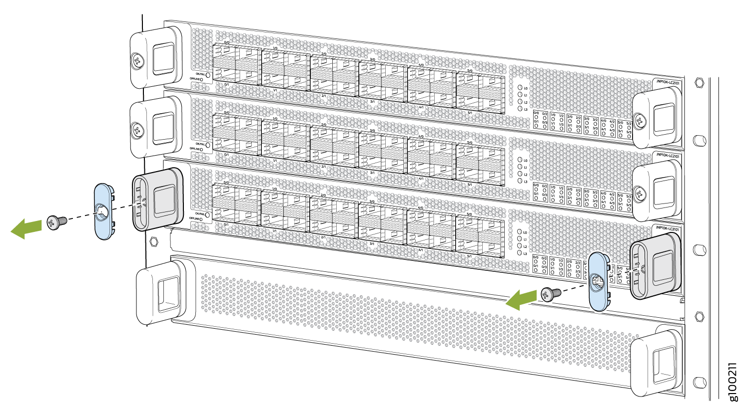
Use the Phillips screwdriver to loosen and remove the
screws on the two line card handles (see Figure 11).
Figure 11: Removing the Screws on the Line Card Handles
-
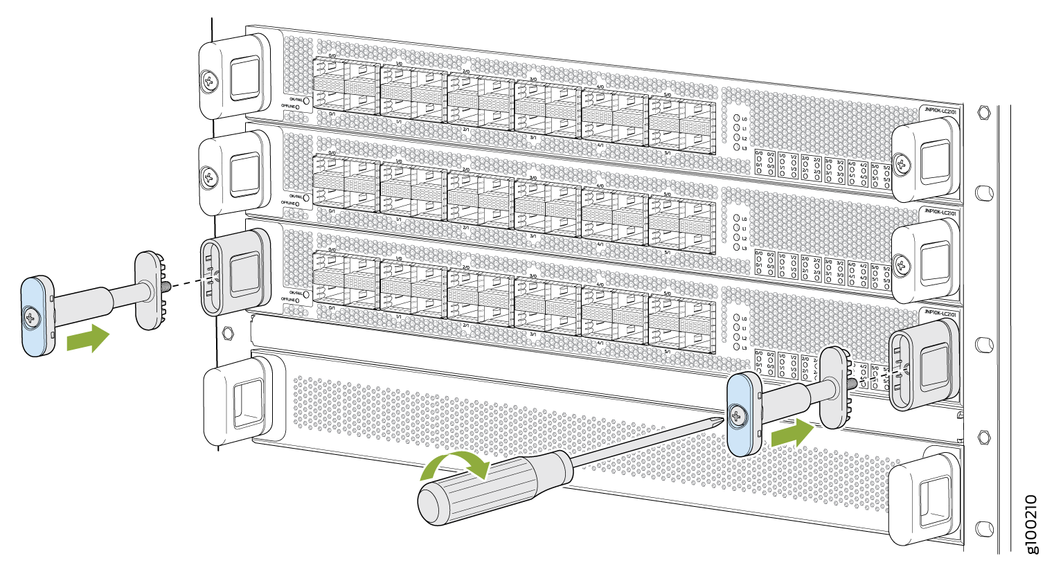
Replace the blue cap on each line card handle with the
two handle extensions (see Figure 12).
Figure 12: Adding Handle Extensions
-
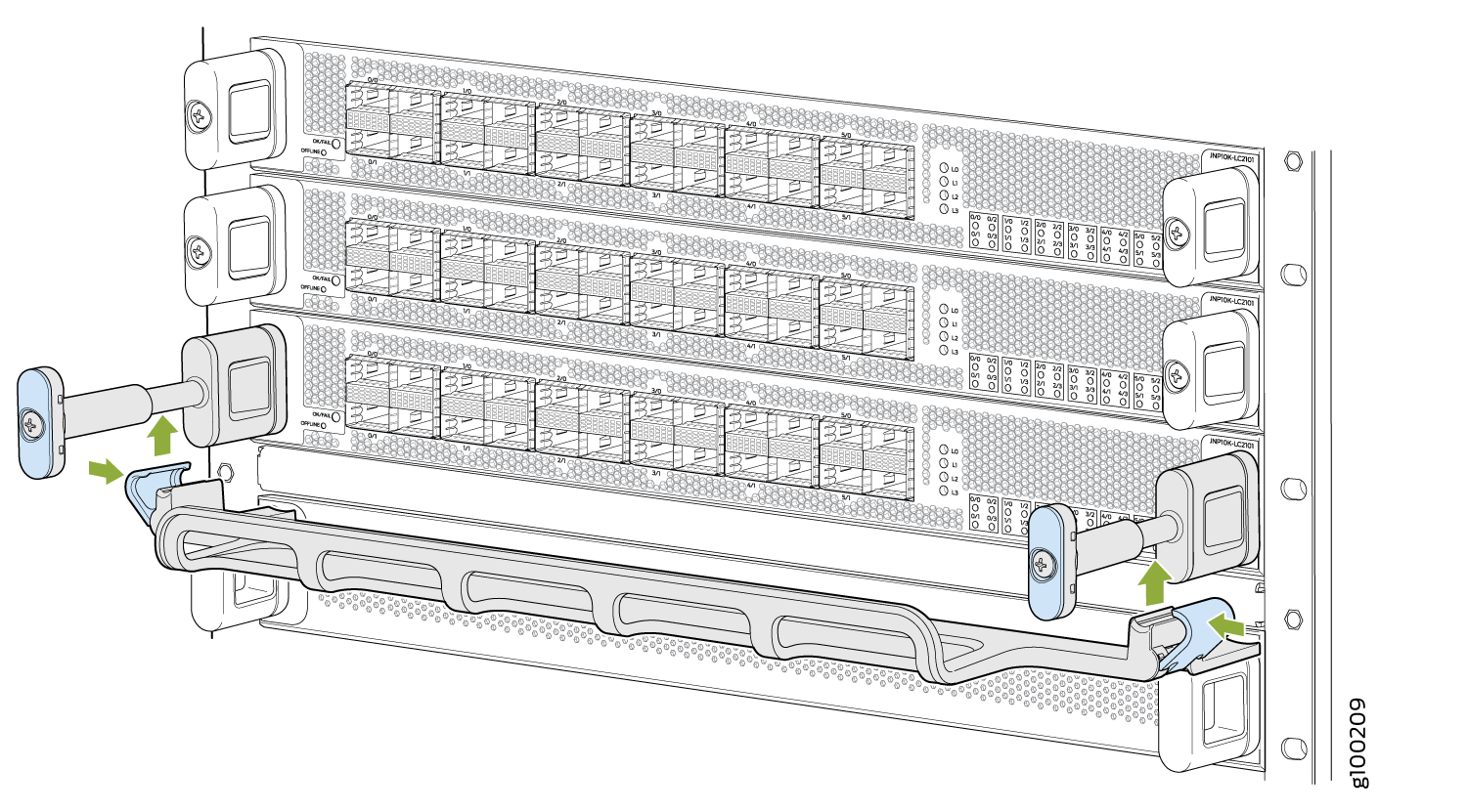
Snap close the blue clips of the cable tray around the
handle extensions (see Figure 13).
Figure 13: Adding the Cable Tray
-
Drape the optical cables using one of the following methods:
-
Drape and tie the optical cables to the side (see Figure 14).
-
Drape some of the cables under the handle extension and some cables over the handle extension.
Figure 14: Completed Cable Management System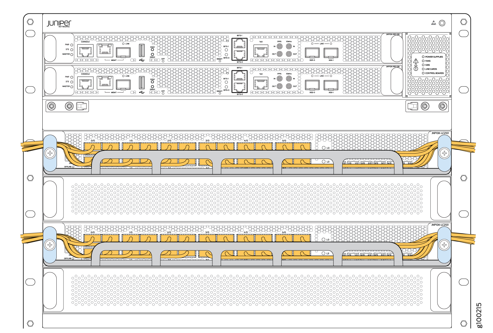
-